Arduino - Buzzer With LDR and LED
by MertArduino in Circuits > Arduino
88889 Views, 72 Favorites, 0 Comments
Arduino - Buzzer With LDR and LED
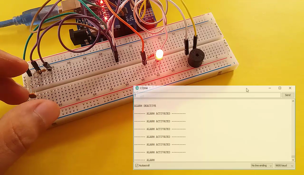
In this project; we will see using LDR to activate a buzzer and an LED. When light shines on LDR; the buzzer will give alarm and the LED will flash.
Hardware Required
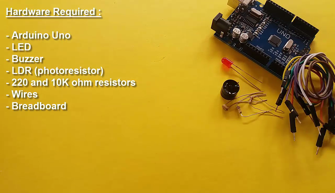
- Arduino Uno
- Buzzer
- LED
- LDR (photoresistor)
- 220 and 10k ohm resistor
- Wires
- Breadboard
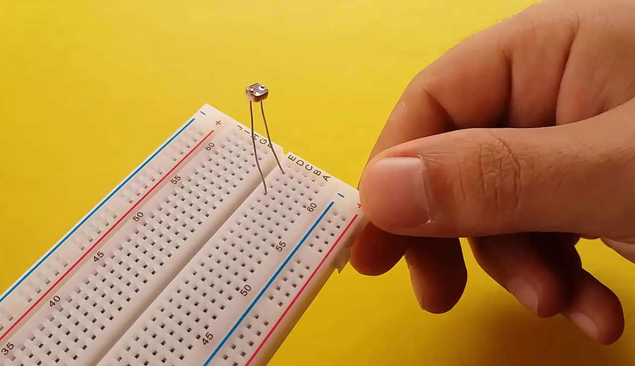
Buzzer - LED - LDR Attach to Board

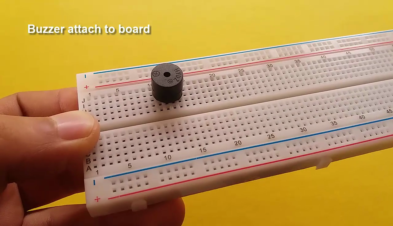
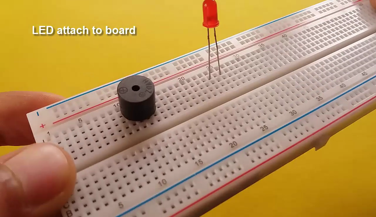
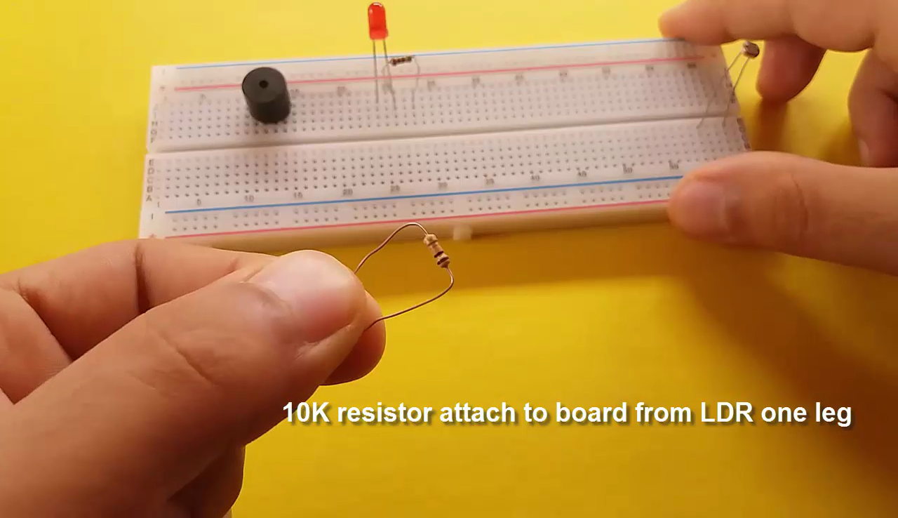
- Buzzer attach to board (the buzzer long leg (+) and short leg (-))
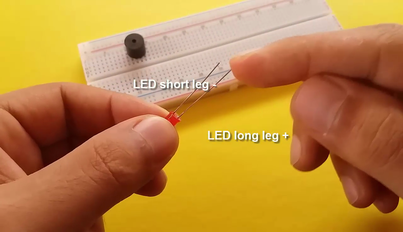
- LED attach to board (the LED long leg (+) and short leg (-))
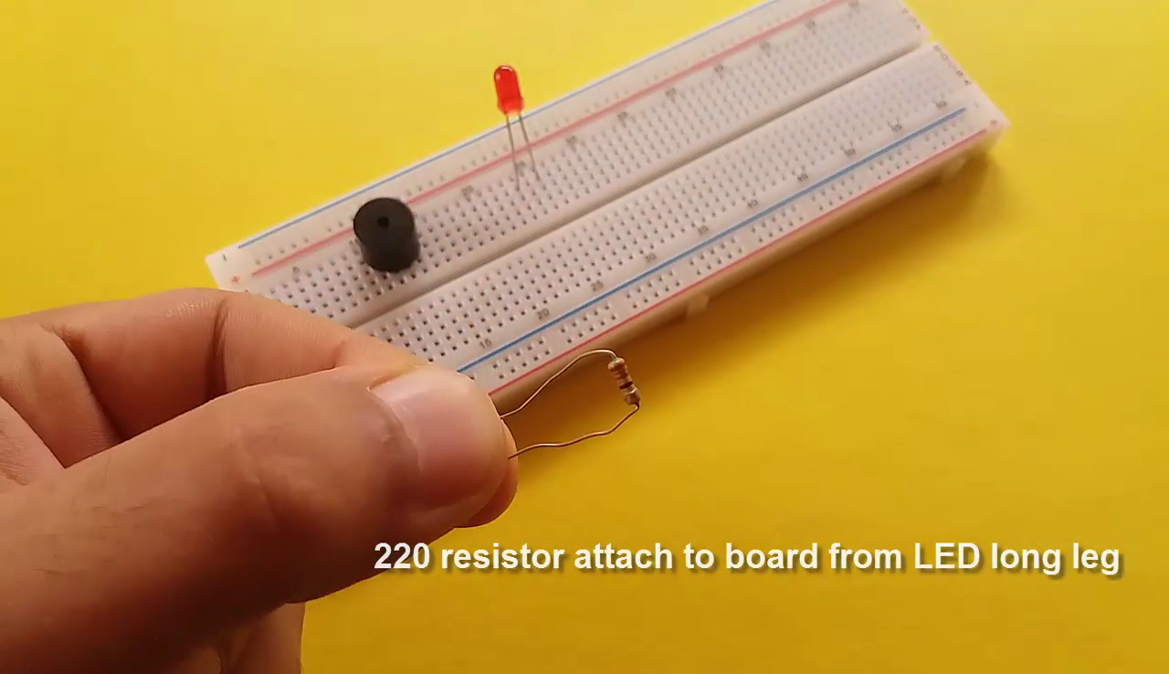
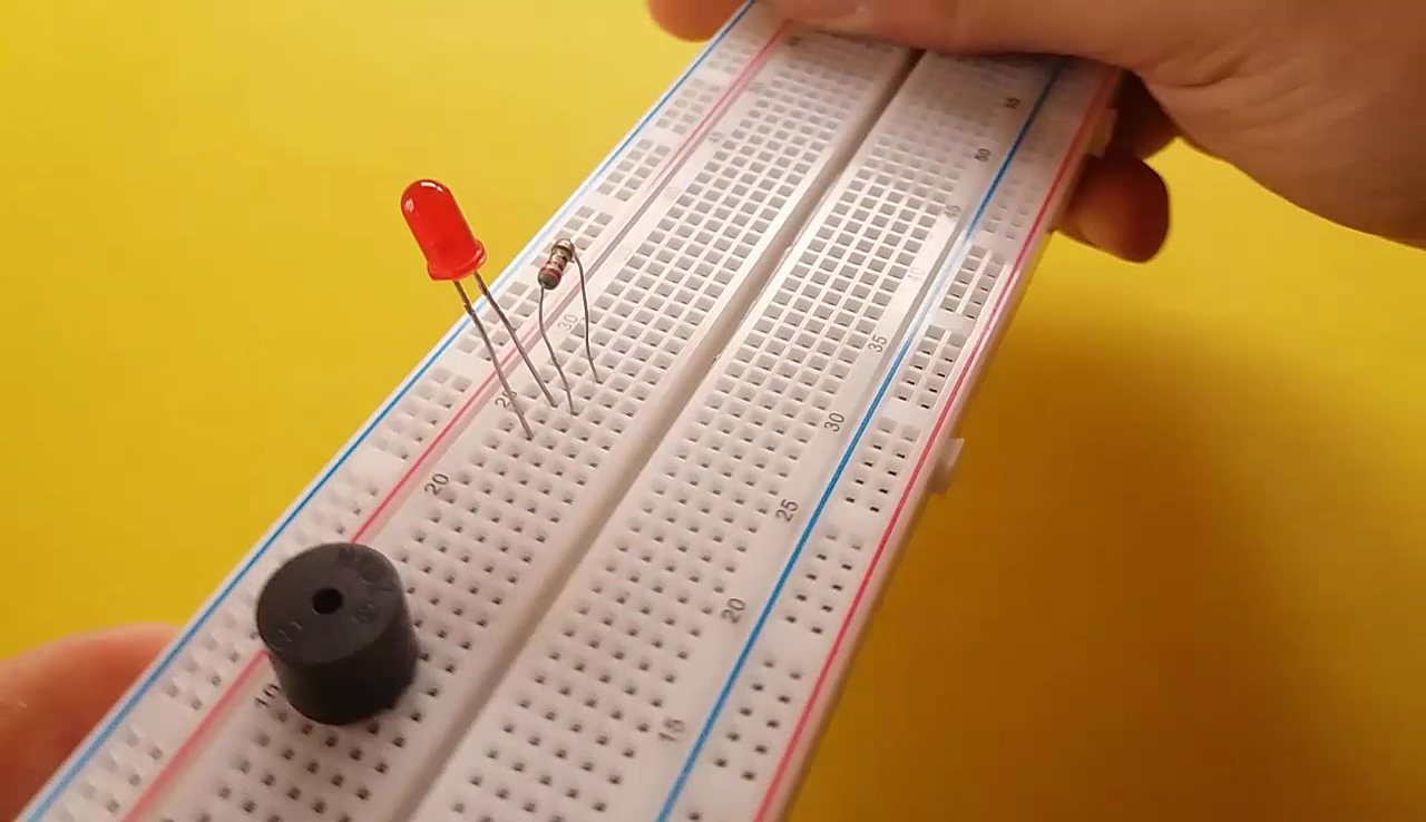
- 220 resistor attach to board from LED long leg (+)
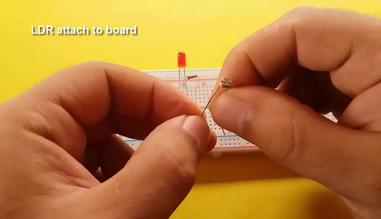
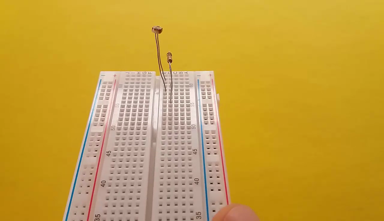
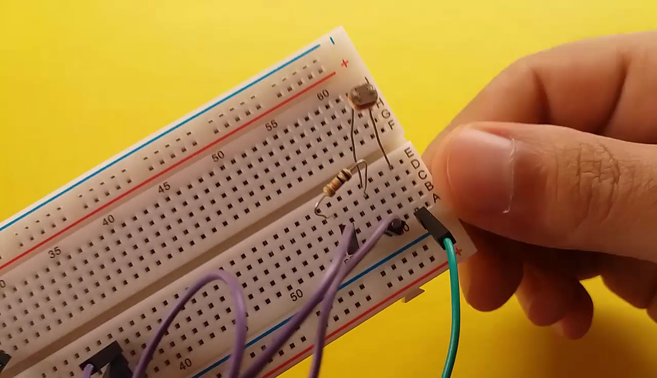
- LDR attach to board
- 10k resistor attach to board from LDR one leg
Arduino Connection
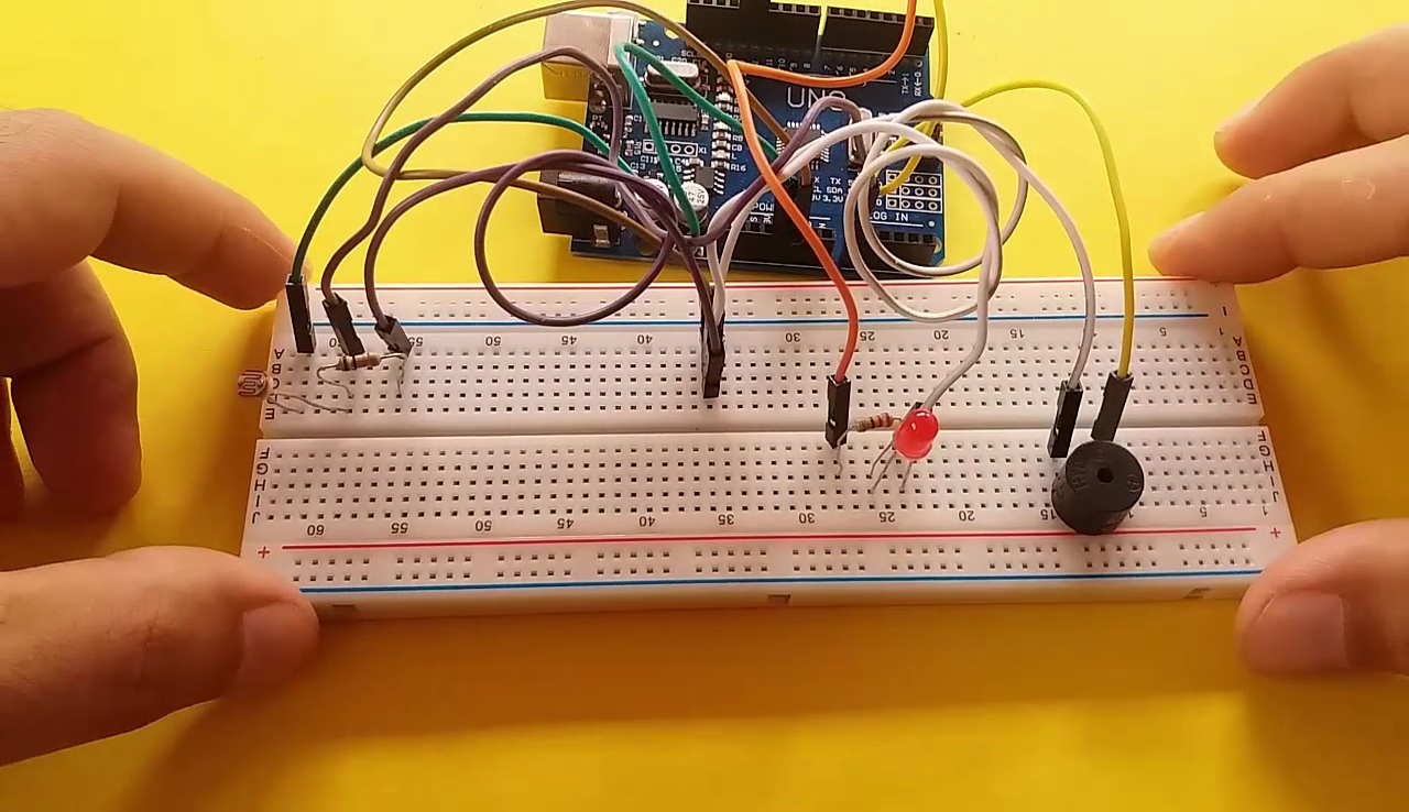
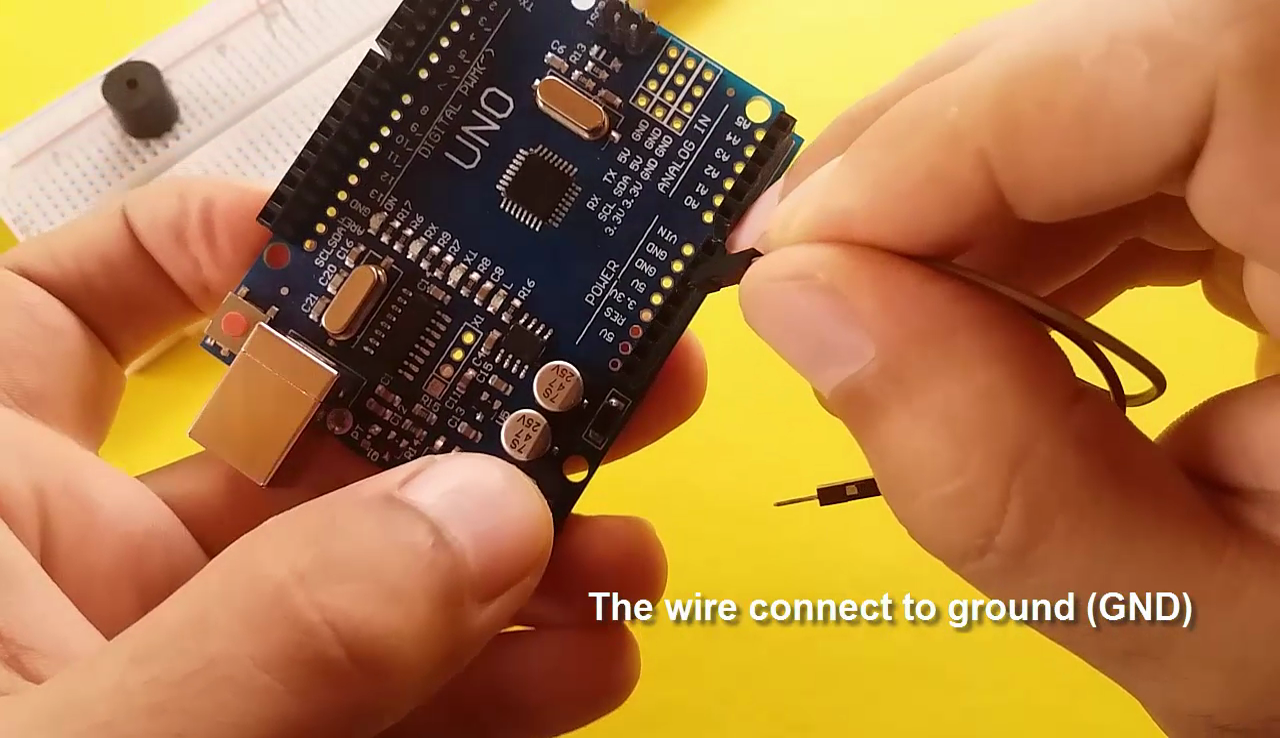
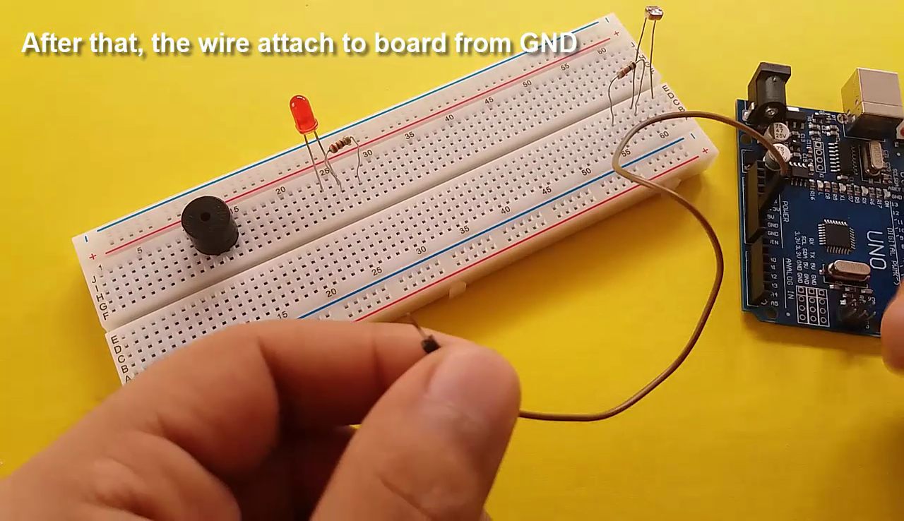
- The wire connect to ground, then the same wire attach to board.
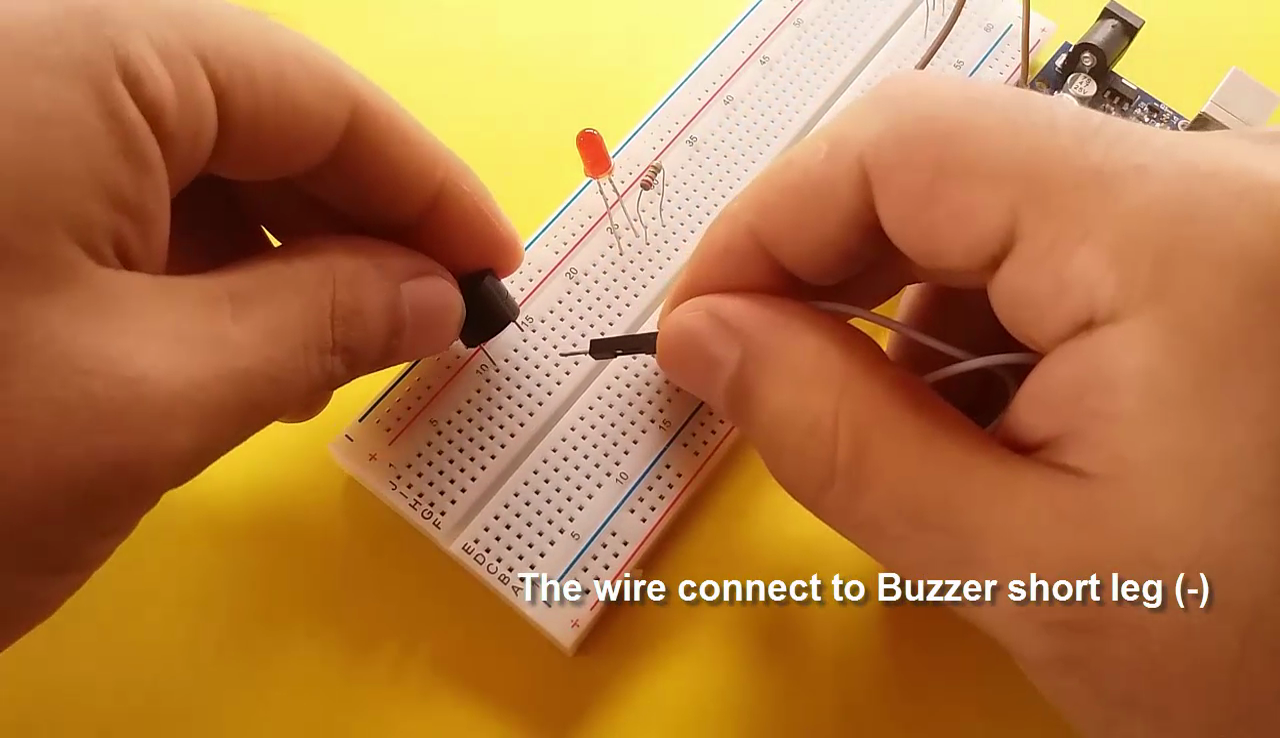
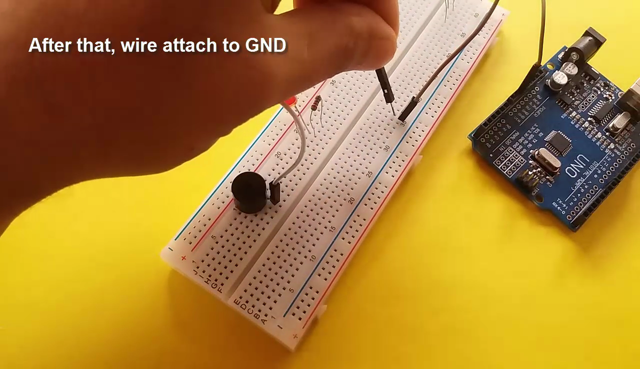
- The wire connect to buzzer short leg, then the same wire attach to GND on the board.
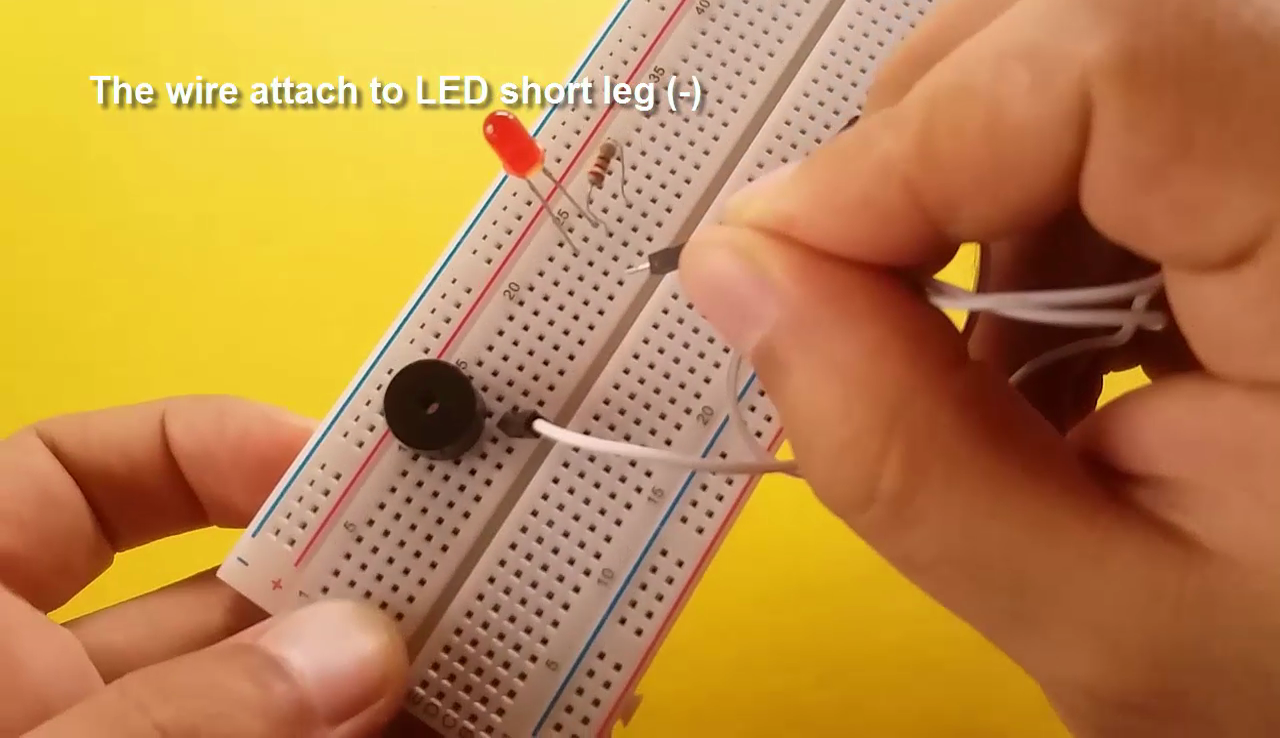
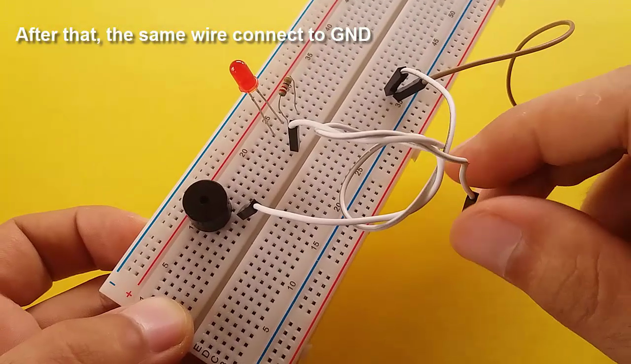
- The wire attach to LED short leg, then the same wire connect to GND on the board.
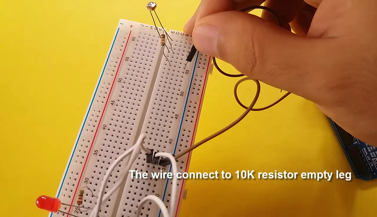
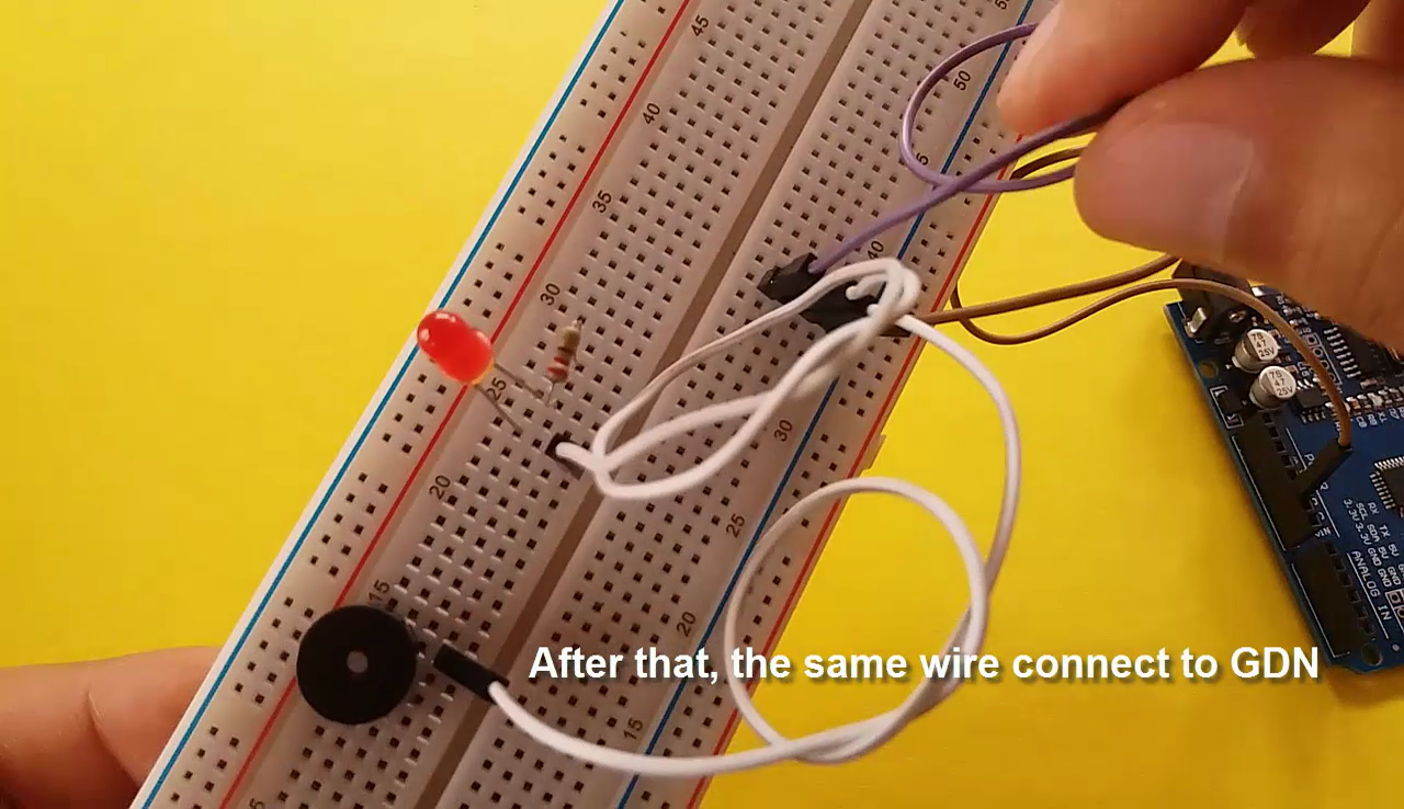
- The wire connect to 10k resistor empty leg, then the same wire connect to GND on the board.
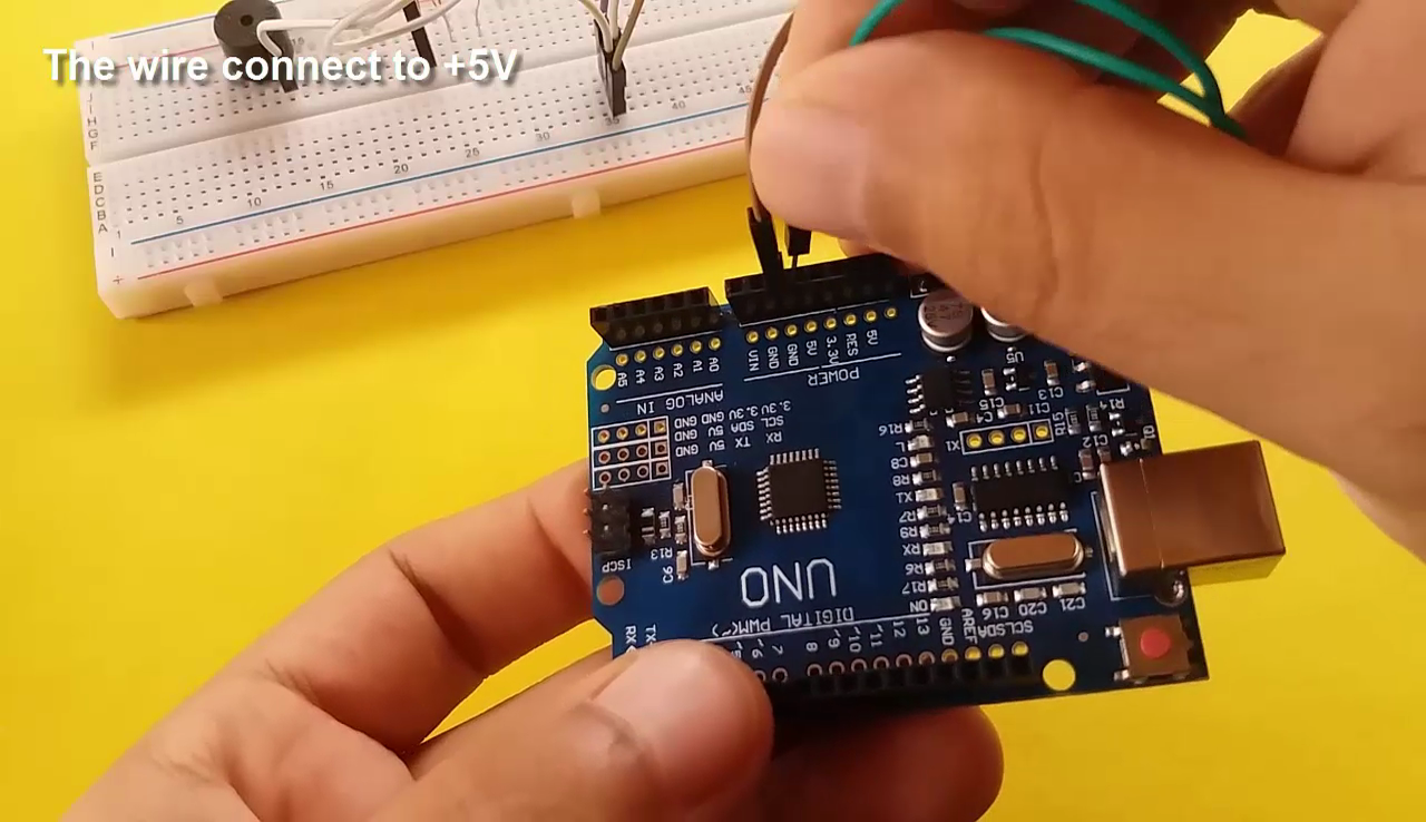
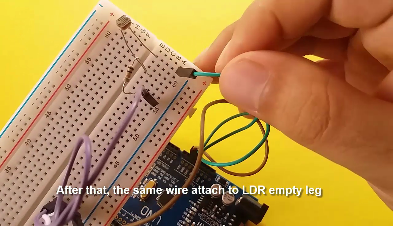
- The wire connect to +5V, then the same wire attach to LDR empty leg.
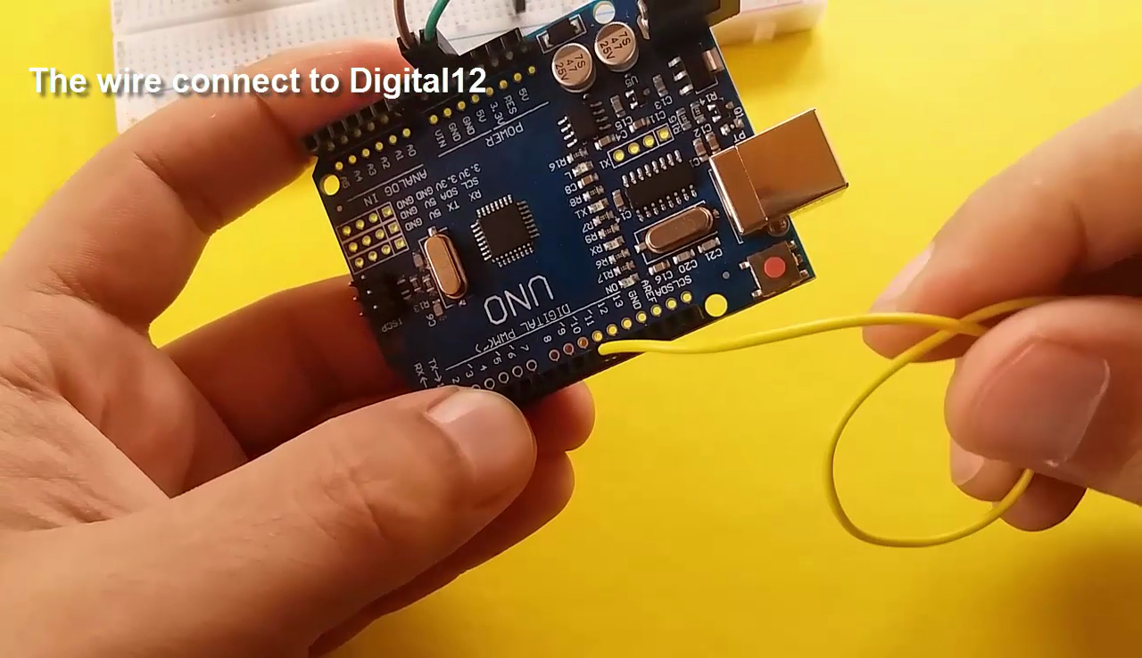
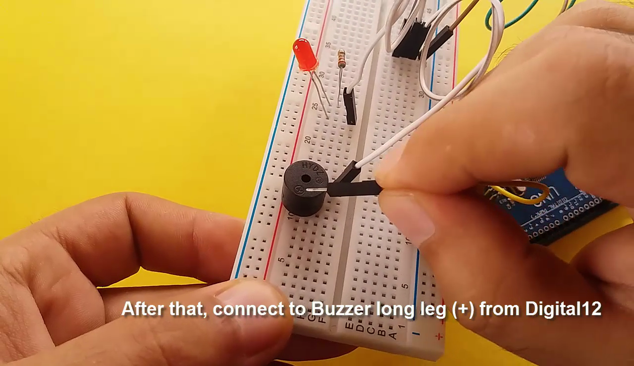
- The wire connect to digital 12, then attach to buzzer long leg.
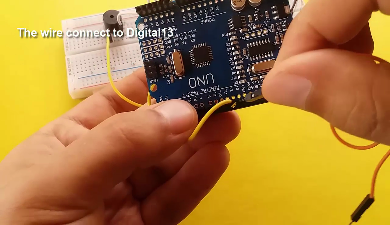
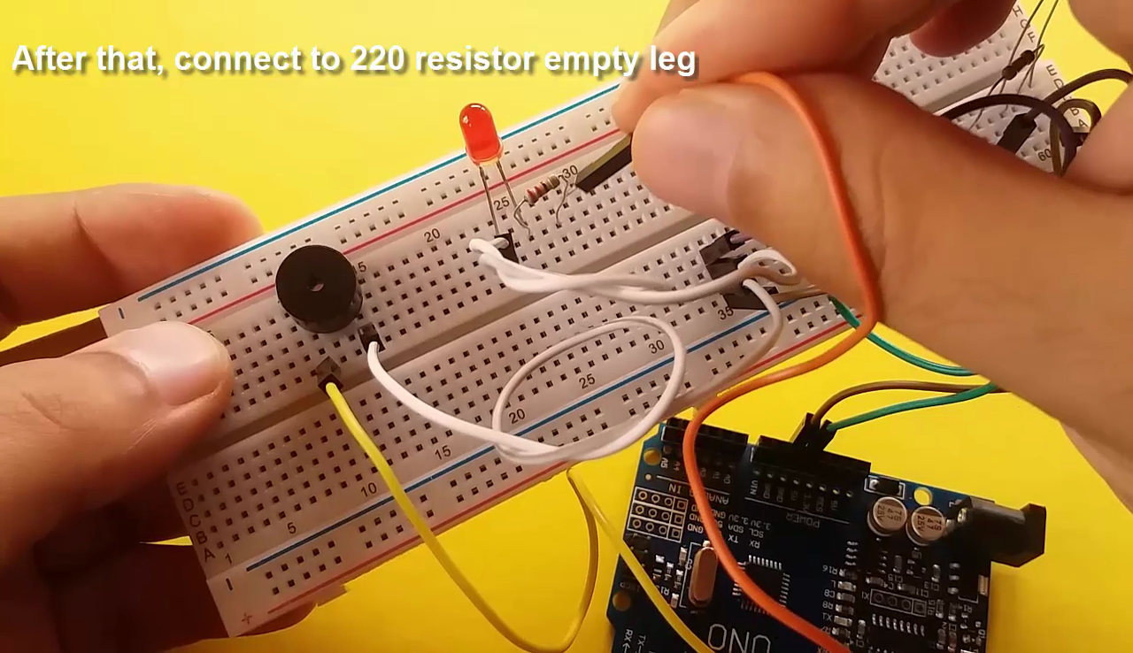
- The wire connect to digital 13, then attach to 220 resistor empty leg.
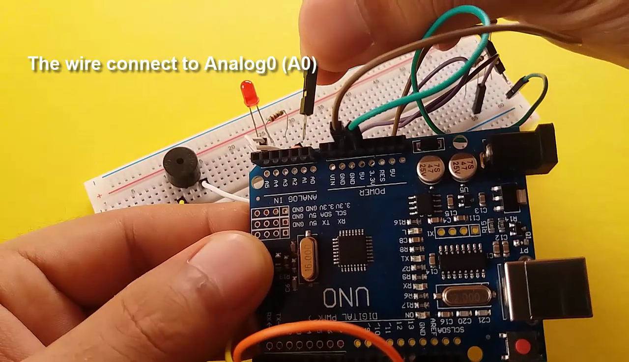
- The wire connect to A0, then attach to LDR's - resistor's same column.
Code
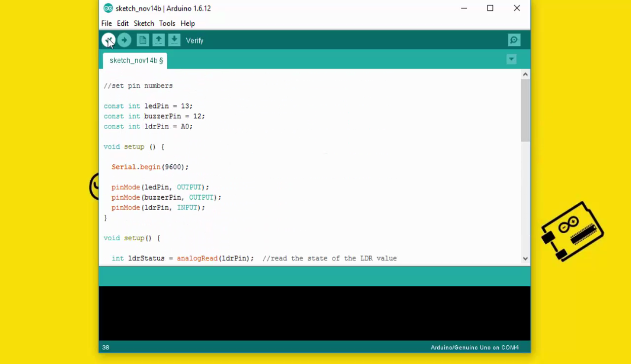
const int ledPin = 13;
const int buzzerPin = 12;
const int ldrPin = A0;
void setup () {
Serial.begin(9600);
pinMode(ledPin, OUTPUT);
pinMode(buzzerPin, OUTPUT);
pinMode(ldrPin, INPUT);
}
void loop() {
int ldrStatus = analogRead(ldrPin);
if (ldrStatus >= 400) {
tone(buzzerPin, 100);
digitalWrite(ledPin, HIGH);
delay(100);
noTone(buzzerPin);
digitalWrite(ledPin, LOW);
delay(100);
Serial.println("----------- ALARM ACTIVATED -----------");
}
else {
noTone(buzzerPin);
digitalWrite(ledPin, LOW);
Serial.println("ALARM DEACTIVATED");
}
}
If It Helps, Please Subscribe
First of all, I would like to thank you for reading this guide ! I hope it helps you.
If you want to support me, you can subscribe my channel and watch my videos.