Arduino Bluetooth HC05 Tutorial | Controlling LED Over Bluetooth Module Hc05 With Arduino
by Utsource in Circuits > Arduino
6839 Views, 1 Favorites, 0 Comments
Arduino Bluetooth HC05 Tutorial | Controlling LED Over Bluetooth Module Hc05 With Arduino
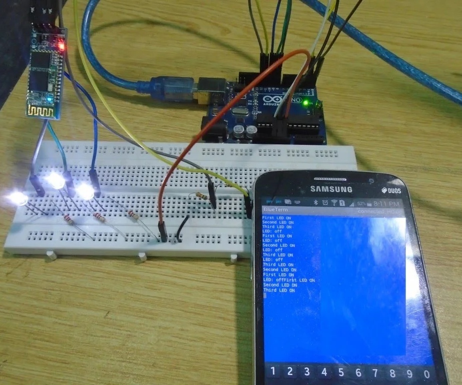
Hi guys in this instructables we will learn how to use Bluetooth Module HC05 with Arduino. We will connect Bluetooth module with arduino to receive commands from smartphone over Bluetooth using HC05 and according to those commands LED will turned off & on using Bluetooth.
Things You Need for This Instructables
.jpg)
These following things you need for this instructables :
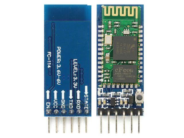
HC-05 Bluetooth module (HC-06 will work too)
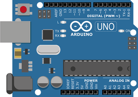
Arduino UNO (Other models will work too)
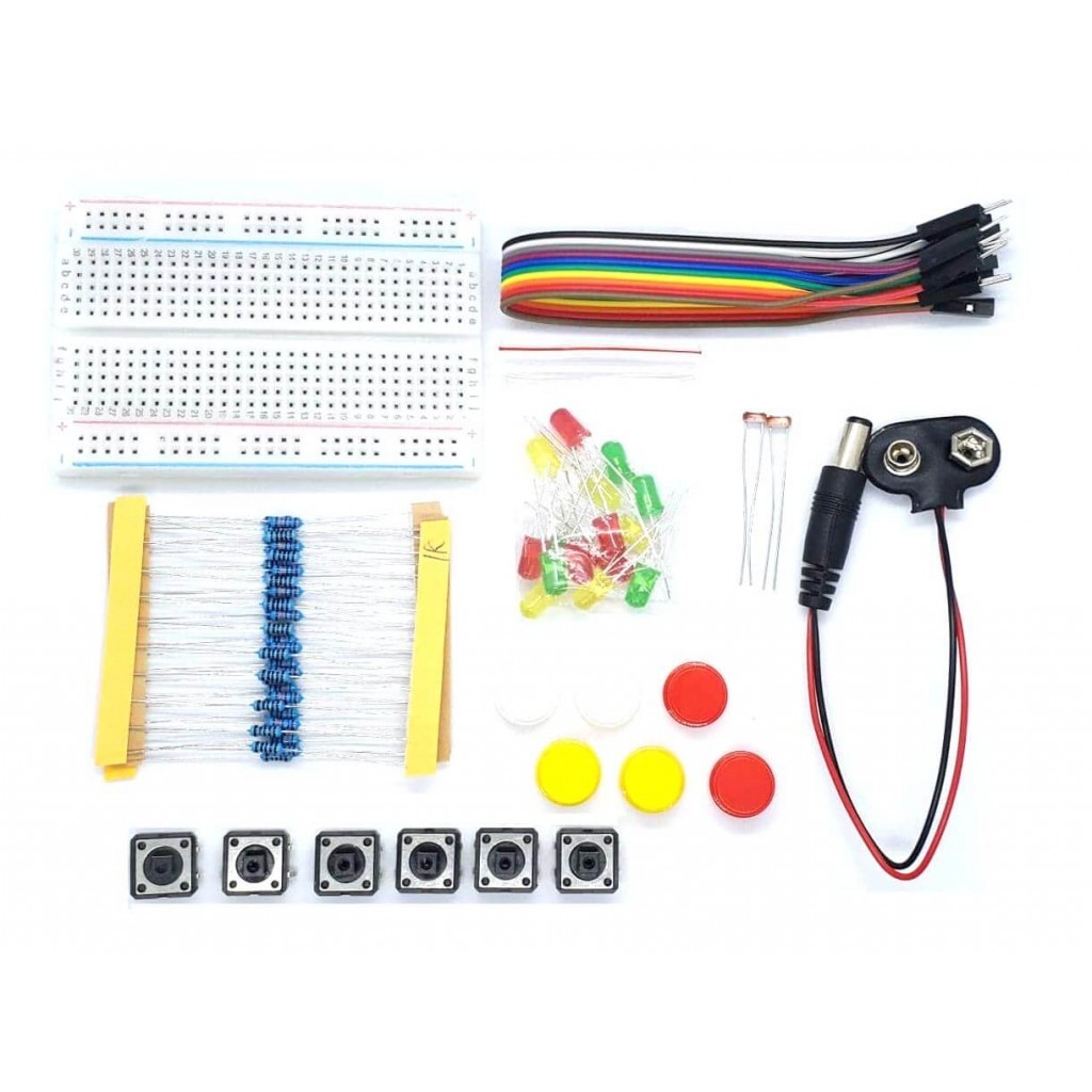
3 X LED’s
3 X 220 ohm resistors
1k and 2k resistor
Connecting wires
Connections
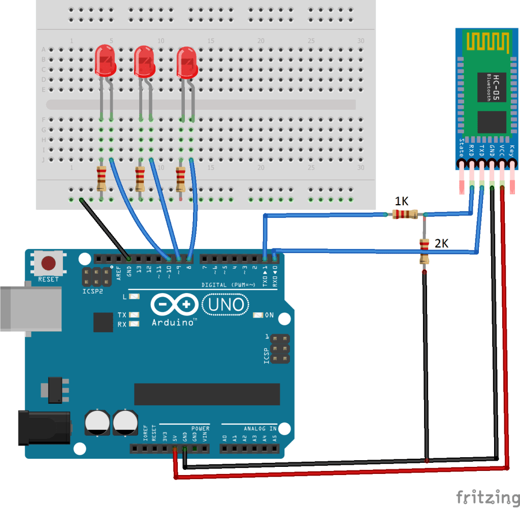
HC-05 Bluetooth module have six pins but we are not going to use the key and state pins because we do not require these in the project. The state command tells that either it is connected or not and the key command forces setup mode if it is brought HIGH before power is applied.
The four pins that we are going to use are the VCC, GND, TXD and the RXD pins. The VCC requires up to 5V to power up while the RXD pin communicates with the Arduino on 3.3V. So, if you will connect it RXD directly to the Arduino then it may work but it will get damage soon. So it is better to make a voltage divider to convert the 5V into 3.3V using the resistors and then connect the RX pin through this to the Arduino.
Connect the VCC and the ground pin of the HC-05 to the 5V and the ground of the Arduino. Then connect the TX to the pin 0 of the Arduino which is the RX pin by default. Then make a voltage divider by connecting the 1k and 2k resistors in series and connect the RX of the HC-05 to the pin 1 of Arduino through the resistors as shown in the figure.
In last, connect three LED’s to the pins 8, 9 and 10 of the Arduino.
Code
.jpg)
Before uploading the code, remove the TX and RX wires from the Arduino and connect these again when the code will be uploaded.
int first_LED = 8;
int second_LED = 9;
int third_LED = 10;
int state;
int flag=0; //makes sure that the serial only prints once the state
void setup() {
// sets the pins as outputs:
pinMode(third_LED, OUTPUT);
pinMode(second_LED, OUTPUT);
pinMode(first_LED, OUTPUT);
Serial.begin(9600);
}
void loop() {
//if some date is sent, reads it and saves in state
if(Serial.available() > 0){
state = Serial.read();
flag=0;
}
if (state == '1') {
digitalWrite(first_LED, HIGH);
if(flag == 0){
Serial.println("First LED ON");
flag=1;
}
}
else if (state == '2') {
digitalWrite(second_LED, HIGH);
if(flag == 0){
Serial.println("Second LED ON");
flag=1;
}
}
else if (state == '3') {
digitalWrite(third_LED, HIGH);
if(flag == 0){
Serial.println("Third LED ON");
flag=1;
}
}
else if (state == '0') {
digitalWrite(third_LED, LOW);
digitalWrite(second_LED, LOW);
digitalWrite(first_LED, LOW);
if(flag == 0){
Serial.println("LED: off");
flag=1;
}
}
}
Test
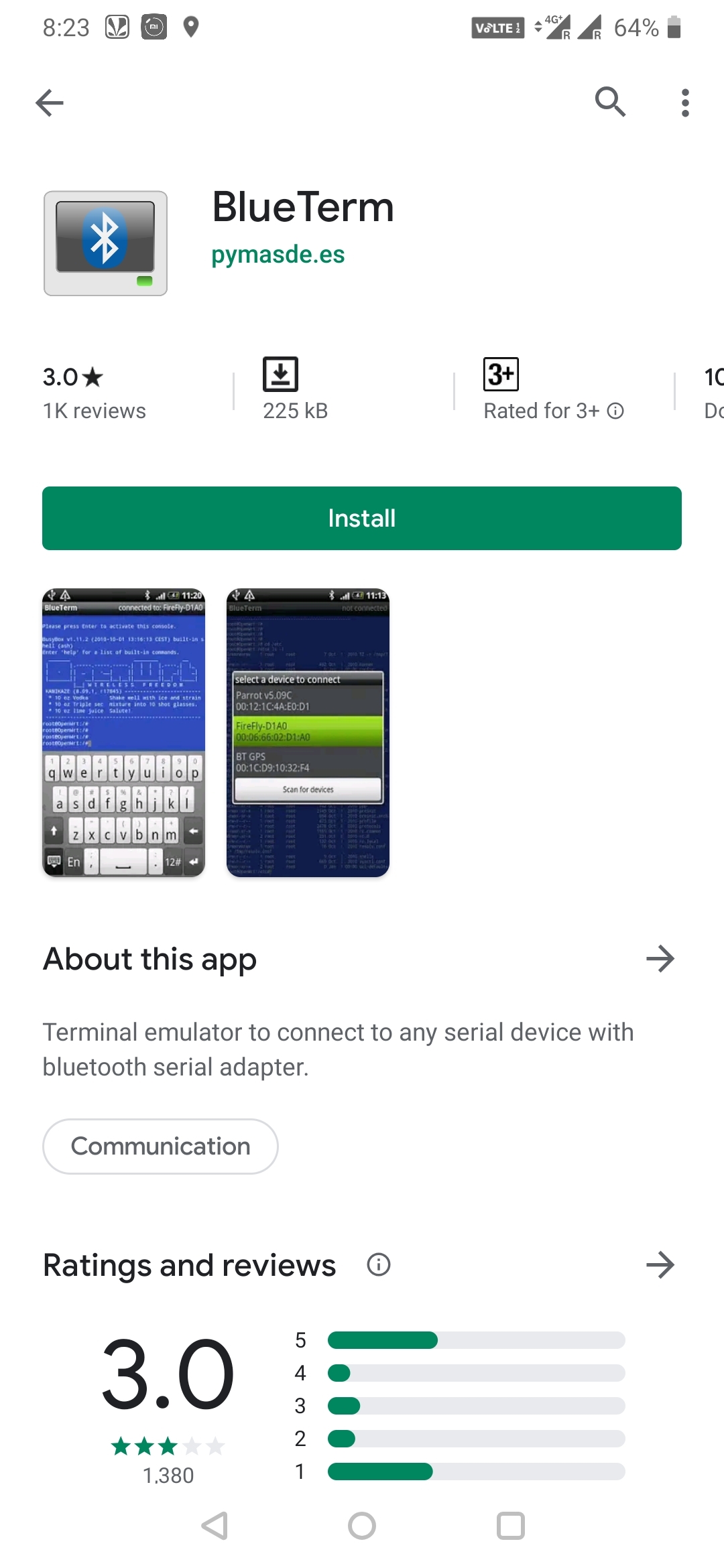
Install the Blueterm android APP from playstore named as BlueTerm. The reason for choosing this APP is that it has greater functionalities than the other Bluetooth APP’s and it is most commonly used APP for Bluetooth communication.
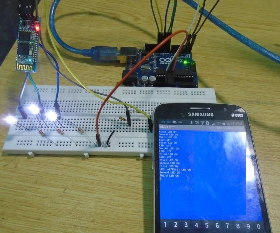
After installing the APP, open it and from the options connect it to the Bluetooth module. After connection, it will show you blue empty screen. Now, when you will type ‘1’ there, then the first LED will light up and when you will type ‘2’, then the second LED will light up and similarly by typing ‘3’, the third led will light up. By typing ‘0’ the LED’s will go down.
After installing the APP, open it and from the options connect it to the Bluetooth module. After connection, it will show you blue empty screen. Now, when you will type ‘1’ there, then the first LED will light up and when you will type ‘2’, then the second LED will light up and similarly by typing ‘3’, the third led will light up. By typing ‘0’ the LED’s will go down.