Arduino Beginner - LED Project (Tinkercad Circuit Included)
by Fahad K S in Circuits > Arduino
297 Views, 0 Favorites, 0 Comments
Arduino Beginner - LED Project (Tinkercad Circuit Included)
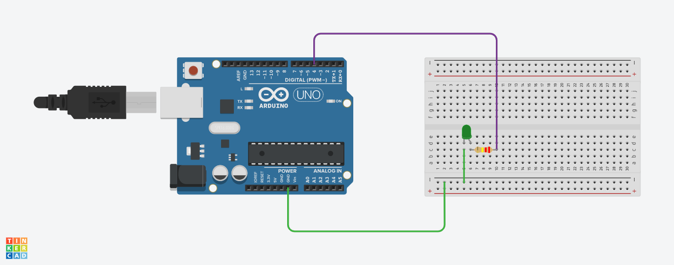
Let's learn a basic Arduino project, where we make a circuit and write the code for a LED blink circuit.
Components Required
- Arduino UNO
- LED
- Resistor 220 ohm
- Connecting Wires
- Breadboard
Feel free to use the tinkercad link provided below if the components are not available.
Arduino Pins
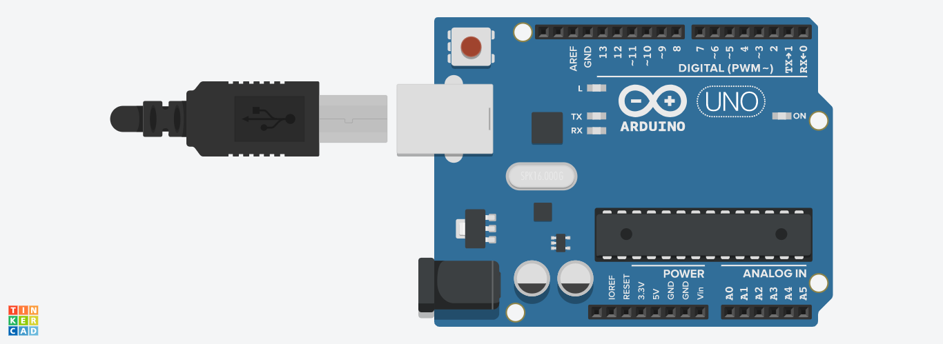
Arduino board had pins where the other components are connected.
Here in our circuit we will be using the Arduino's DigitalPin. Arduino UNO has 14 DigitalPins which can be used to connect to digital components. Another pin that comes to our interest is the GND (ground) Pin, there are three GND pins in the Arduino UNO board.
Connecting LED and Resistor
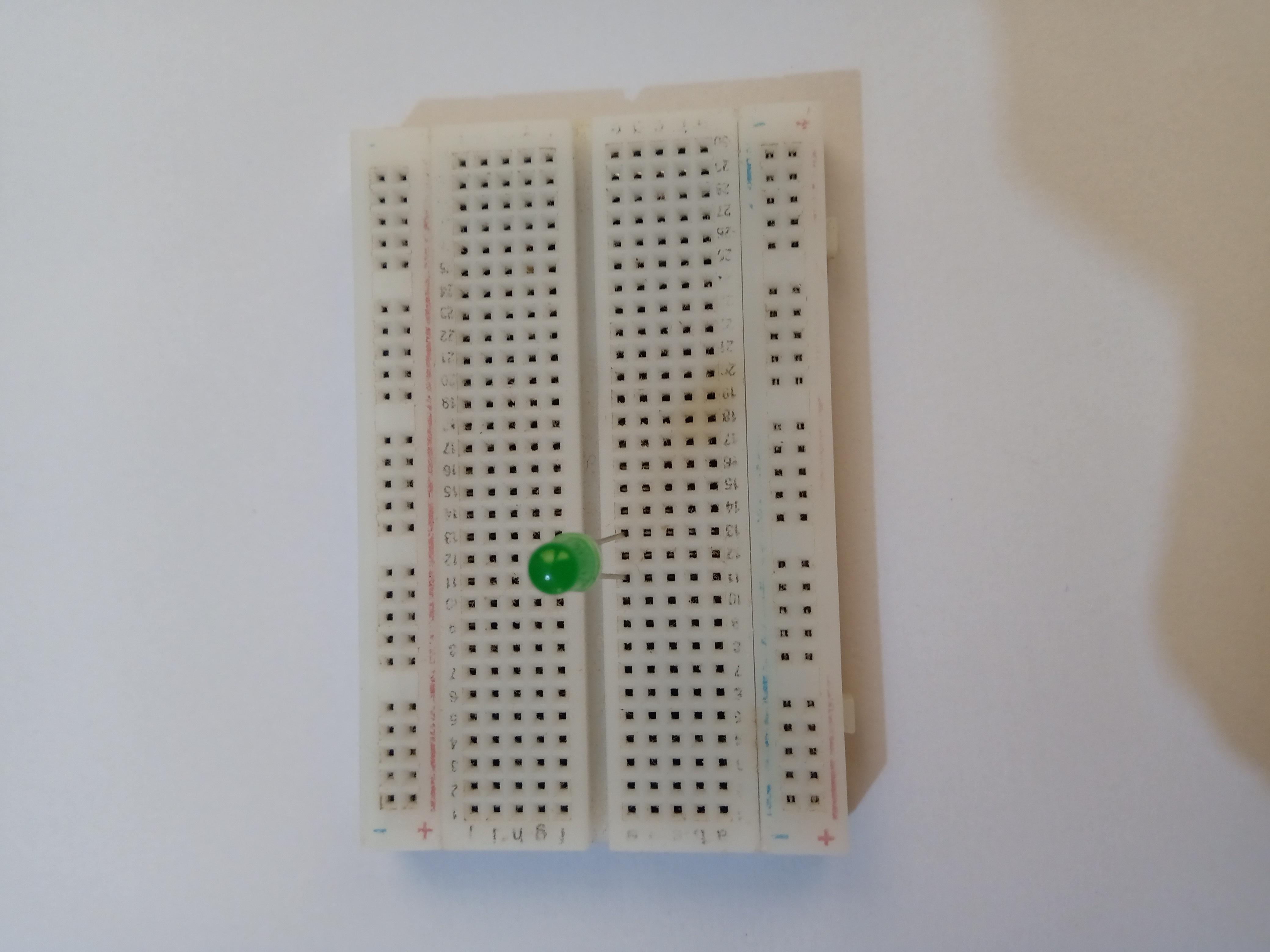
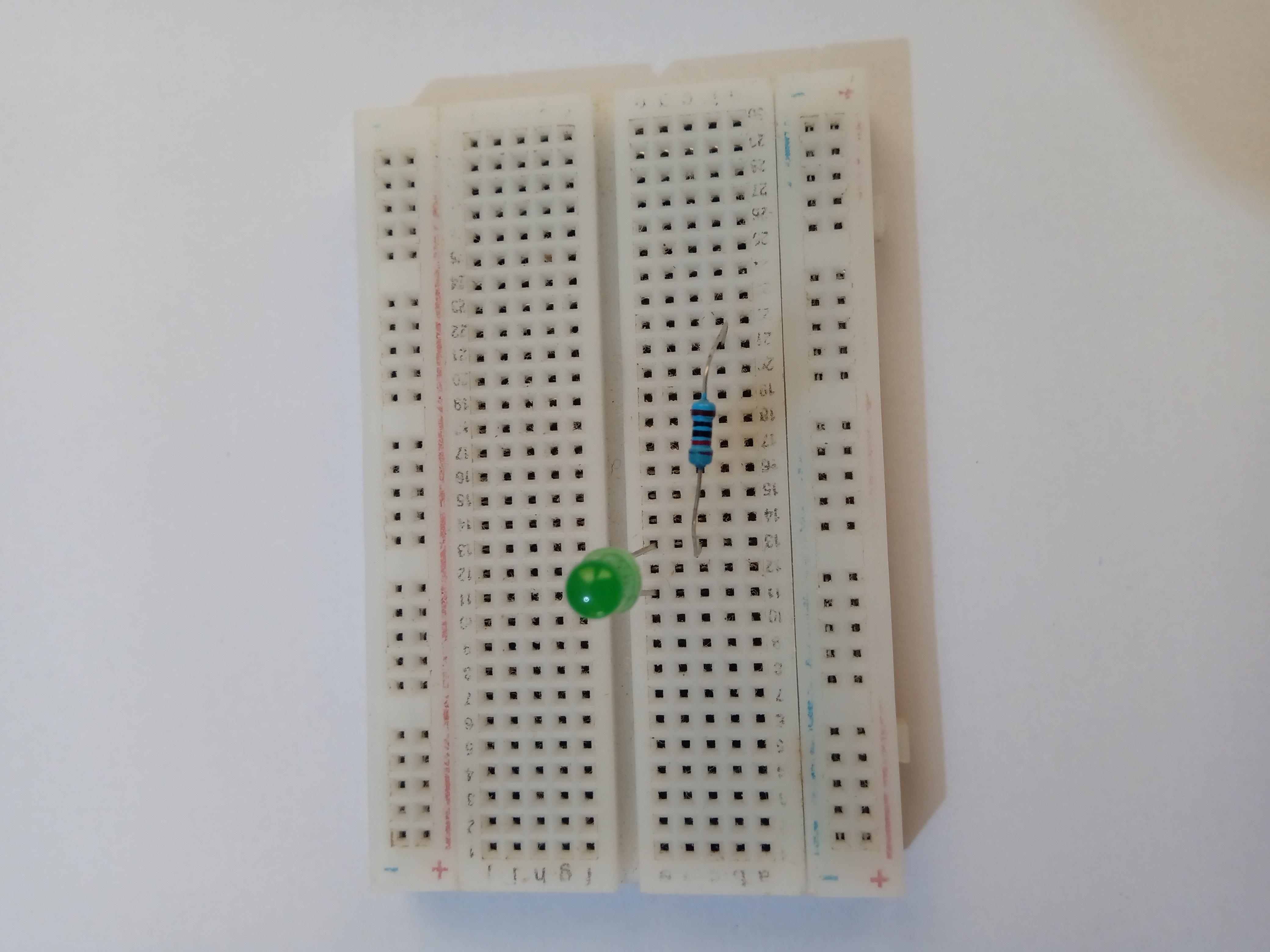
- Connect both the legs of the LED onto the breadboard.
- Take a 220 ohm resistor and place any one of it's leg to the LED's anode (Longer leg which is the positive)
Connecting Wires
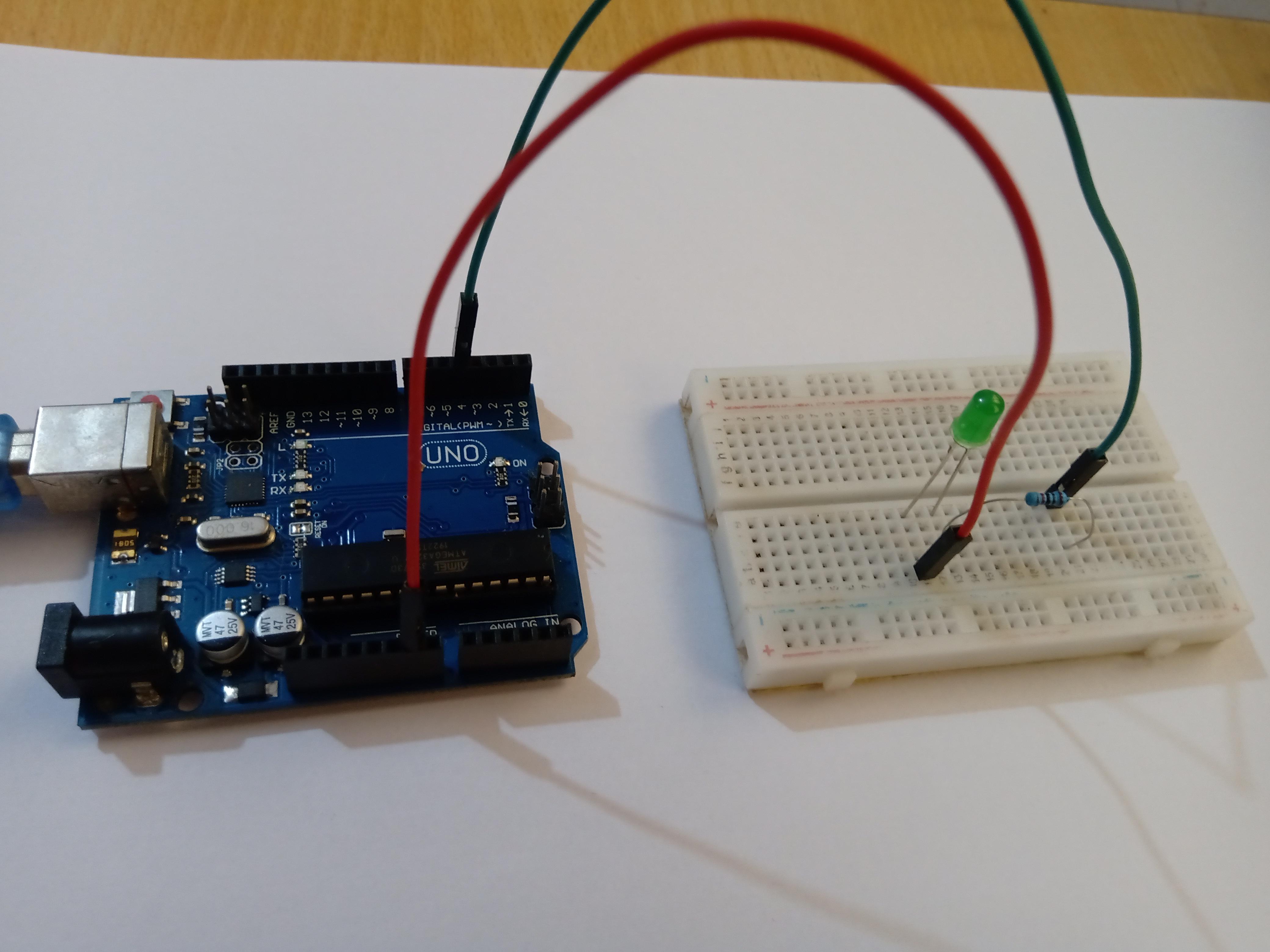
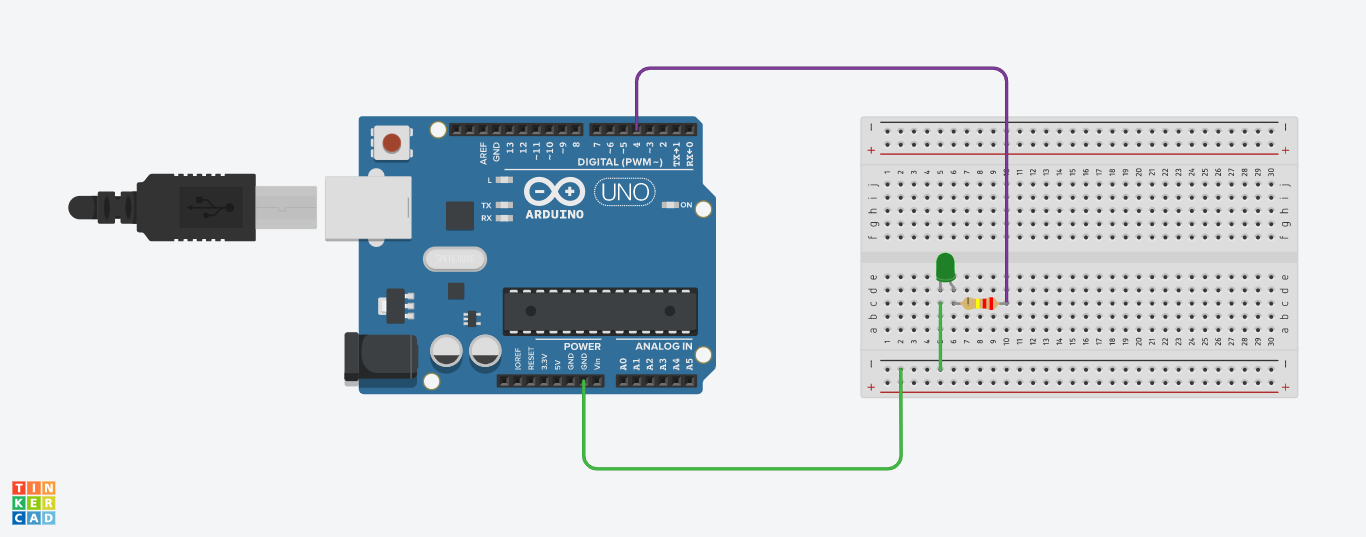
- Connect a wire from the Resistor to any one of the digital pins in the arduino board , here the wire is connected to Pin 4.
- Connect another wire from the cathode of the LED to the GND pin of the arduino board.
Code Explanation
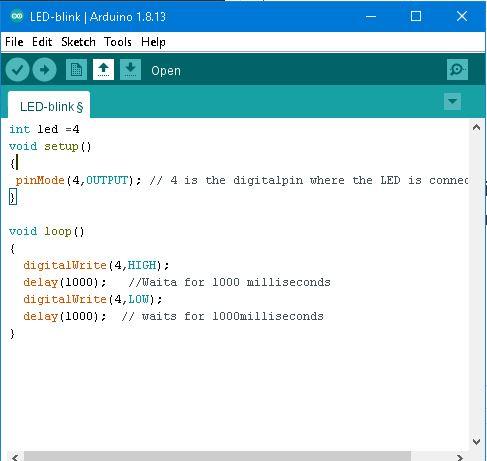
- Initialize the digital pin 4
int ledPin = 4;
- Every code written in Arduino contains two important parts of which one is 'vois main' and 'void loop', void main contains the code to be run only once when the program is run. Whereas the void loop contains the code that runs continuously until the program is terminated.
void setup()
{.
pinMode(4,OUTPUT);
}
- pinMode is used to assign the digital pin 4 as the output pin
void loop()
{
- DigitalWrite is use to assign the value for the output pin
digitalWrite(4,HIGH);
delay(1000);
digitalWrite(4,LOW);
delay(1000);
}
CODE
