Arduino Based Watch - OLED, Menu, RTC
by jiaronghu8 in Circuits > Arduino
11852 Views, 41 Favorites, 0 Comments
Arduino Based Watch - OLED, Menu, RTC
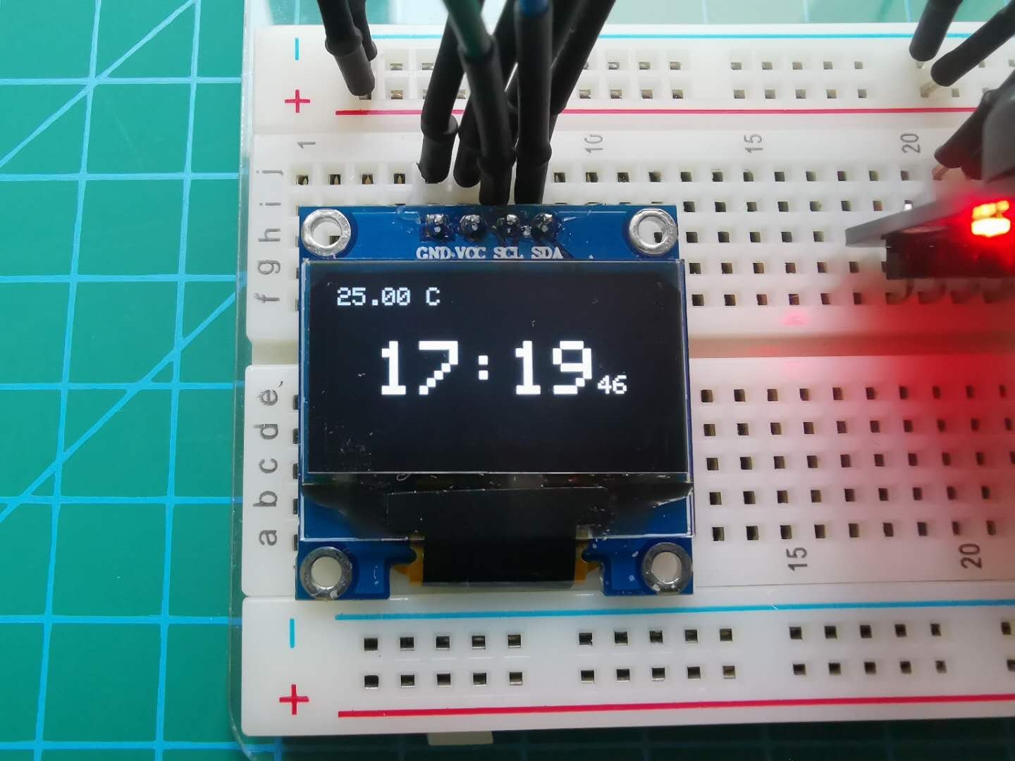
Have you ever wanted a device which is too large for a watch but yet too small for a clock?
Well, it is, but it can easily be made into a watch, and also easily be made into a clock (like a mini clock, you know what I mean)
Note: This is Open Source as I have decided to make it, but still credit me if this is used in other projects or taken inspiration
Note AGAIN: This is an Unfinished Project and with an Arduino nano, a smaller watch can be made.
Lets Start!
Video & Pictures of It in ACTION!
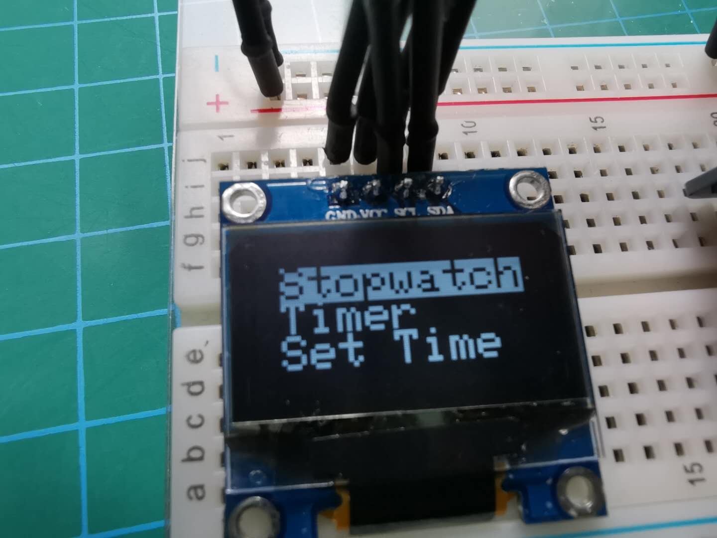
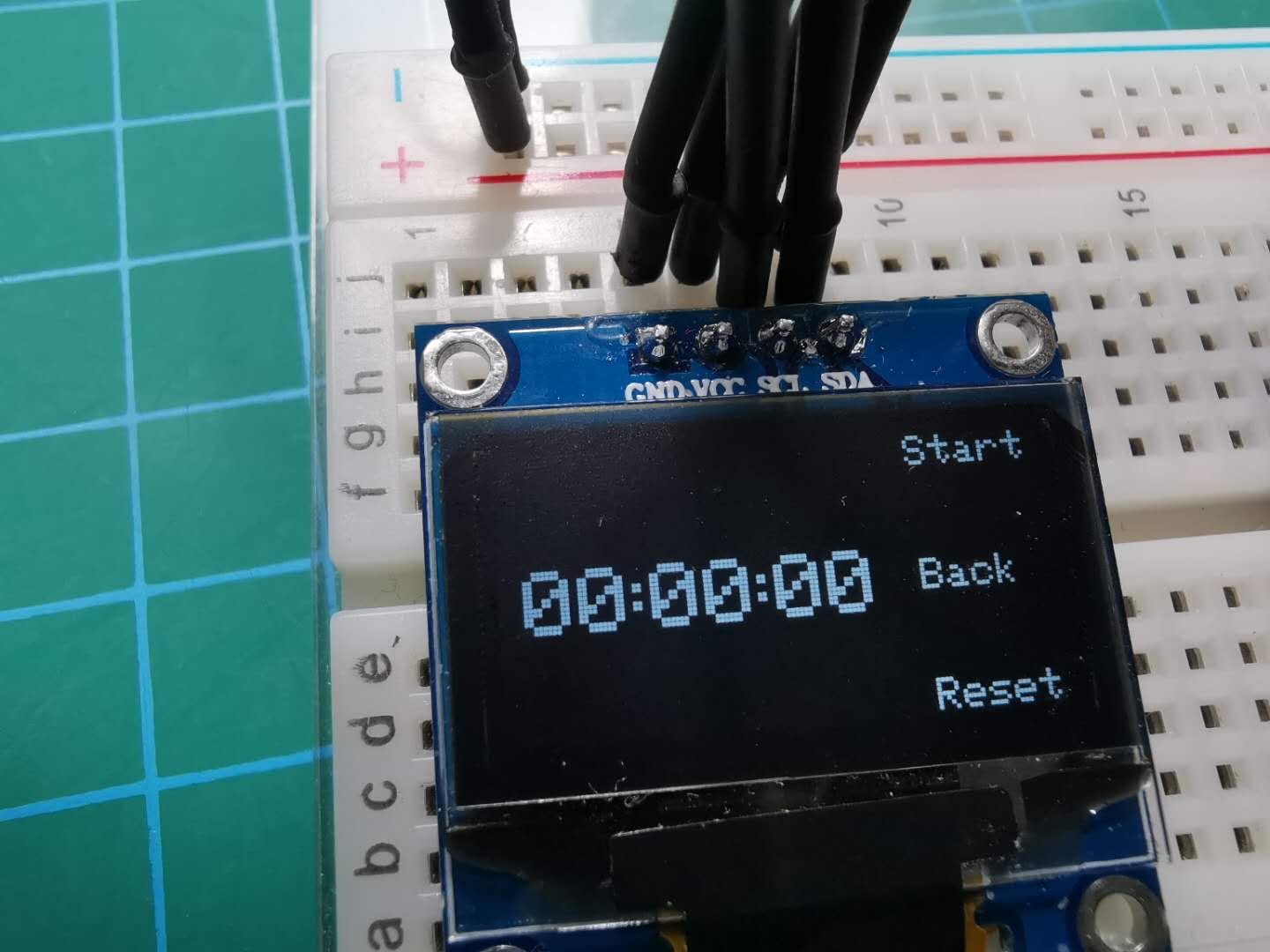
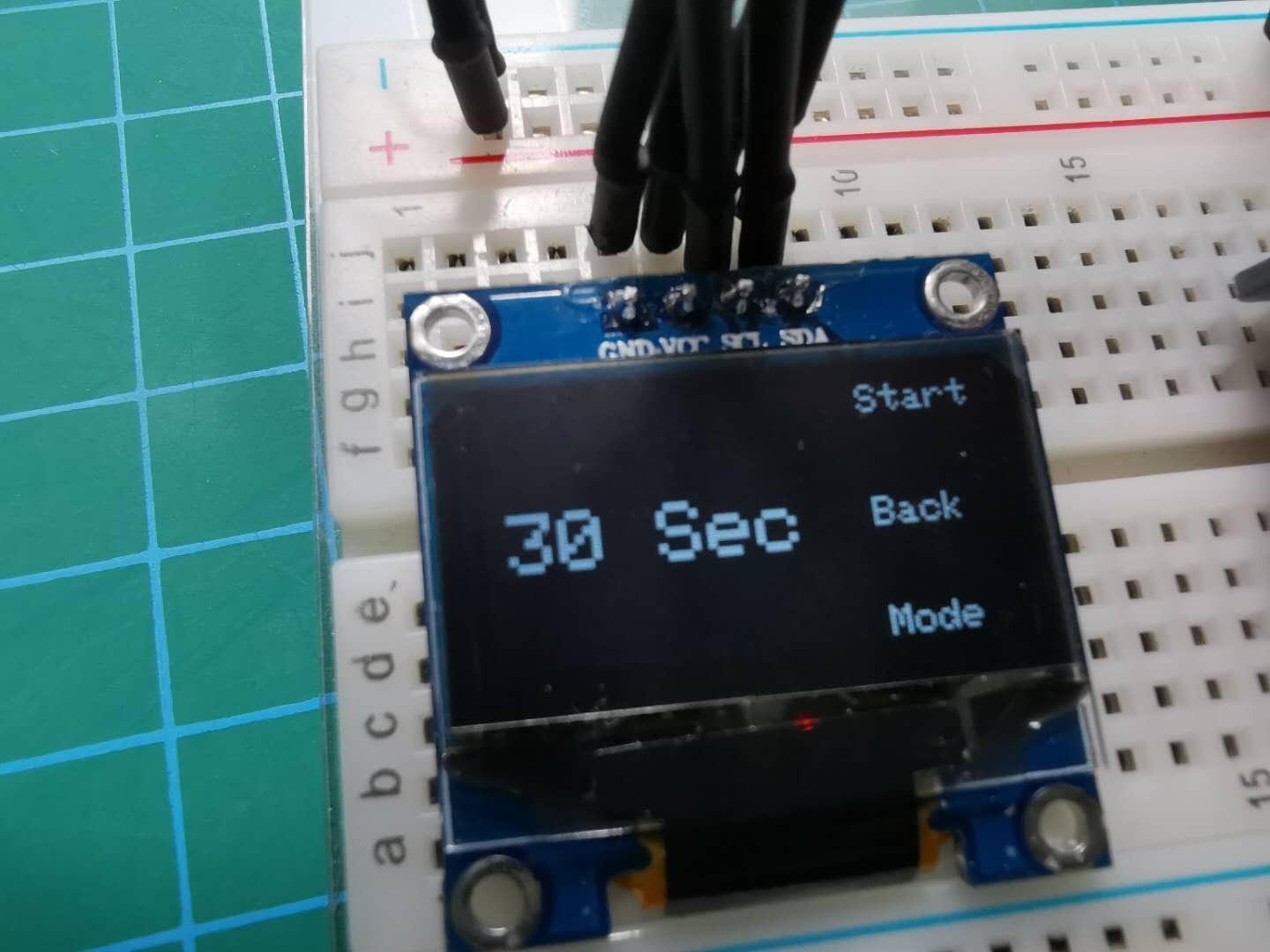
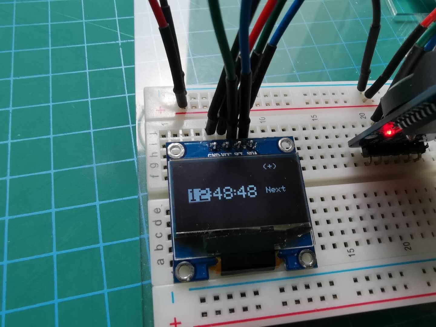
Here, you can see the features of the watch, including:
stopwatch
timer
set time
tell time
tell temperature through rtc module
Supplies Needed:
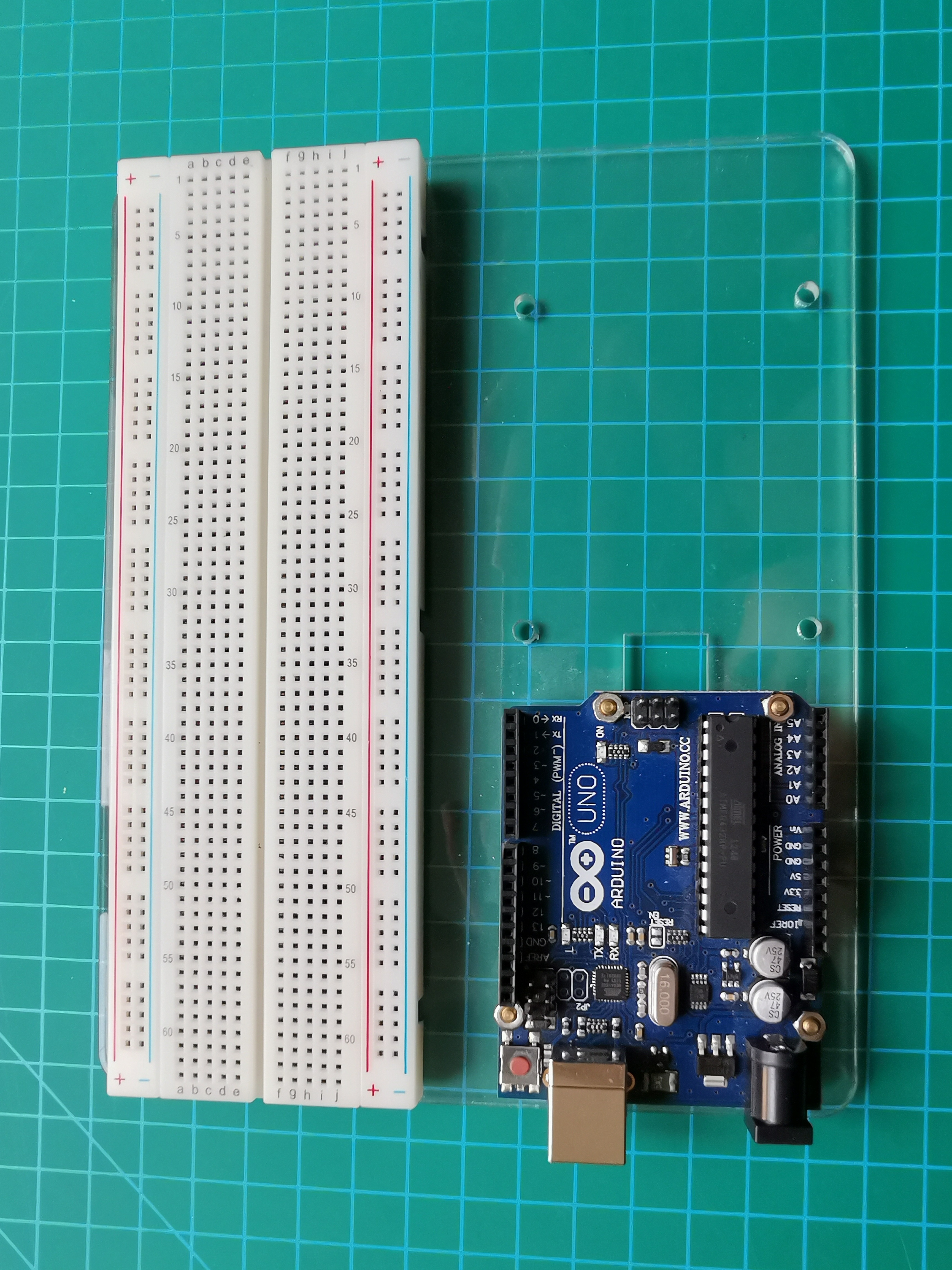
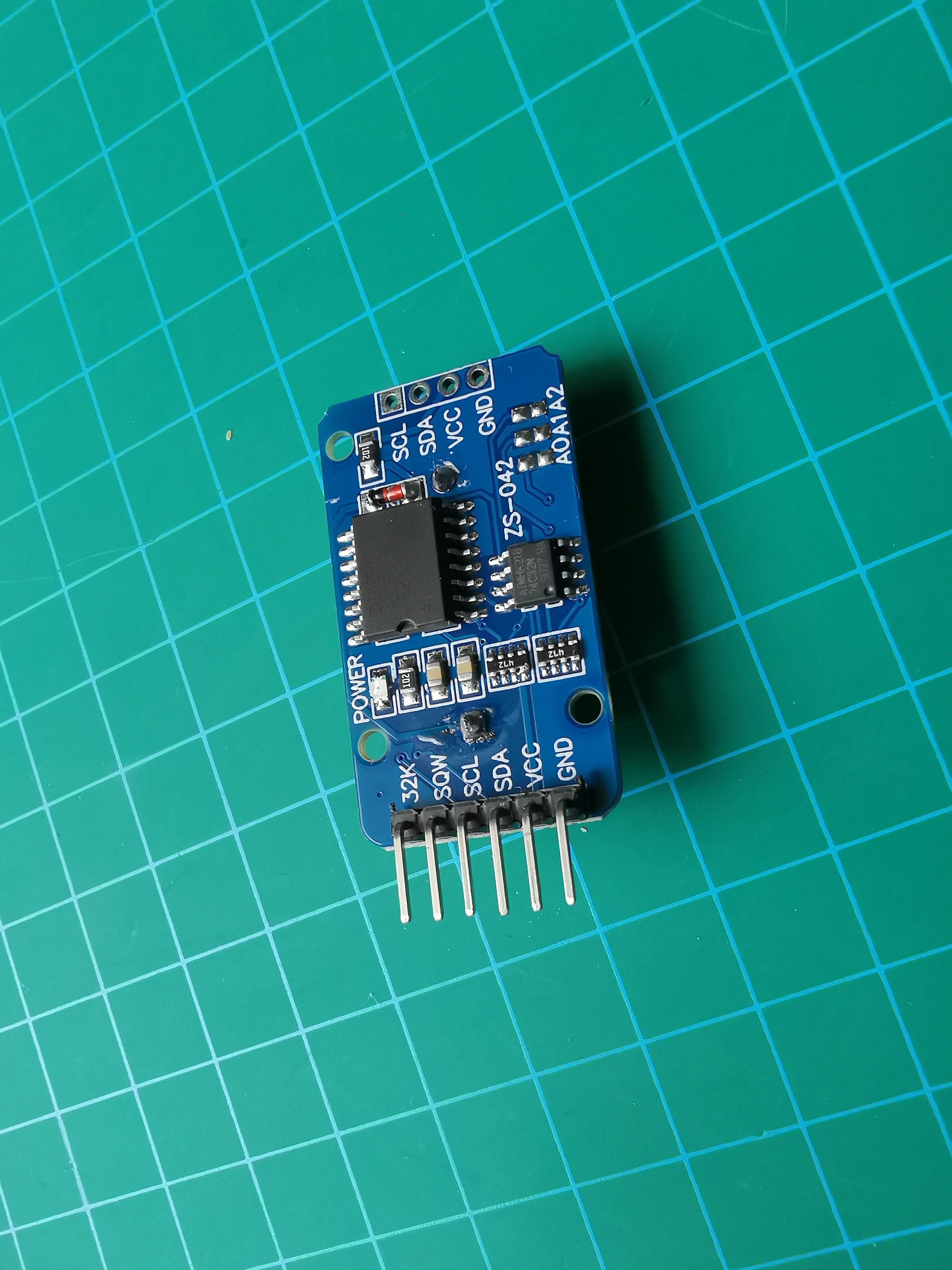
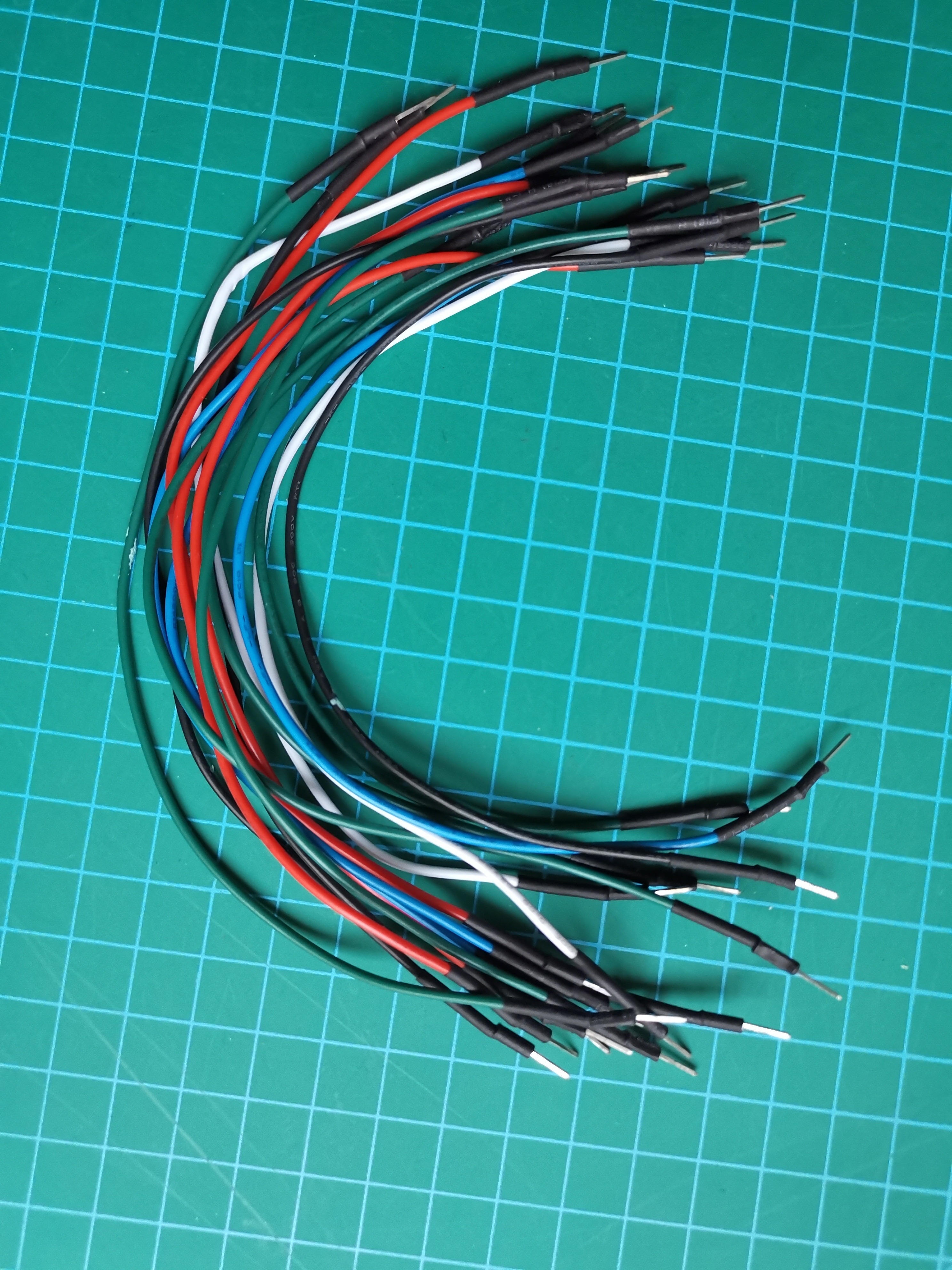
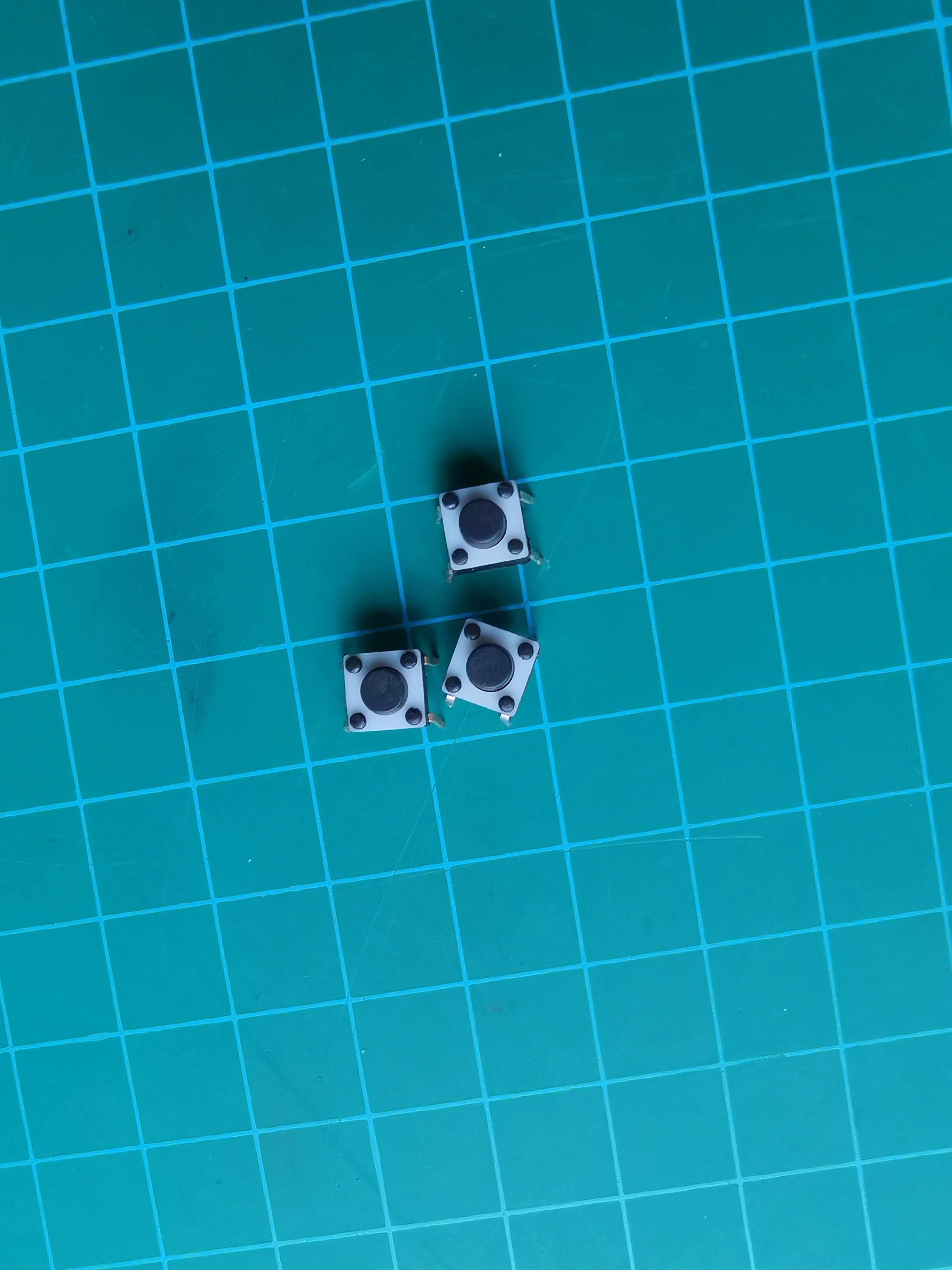
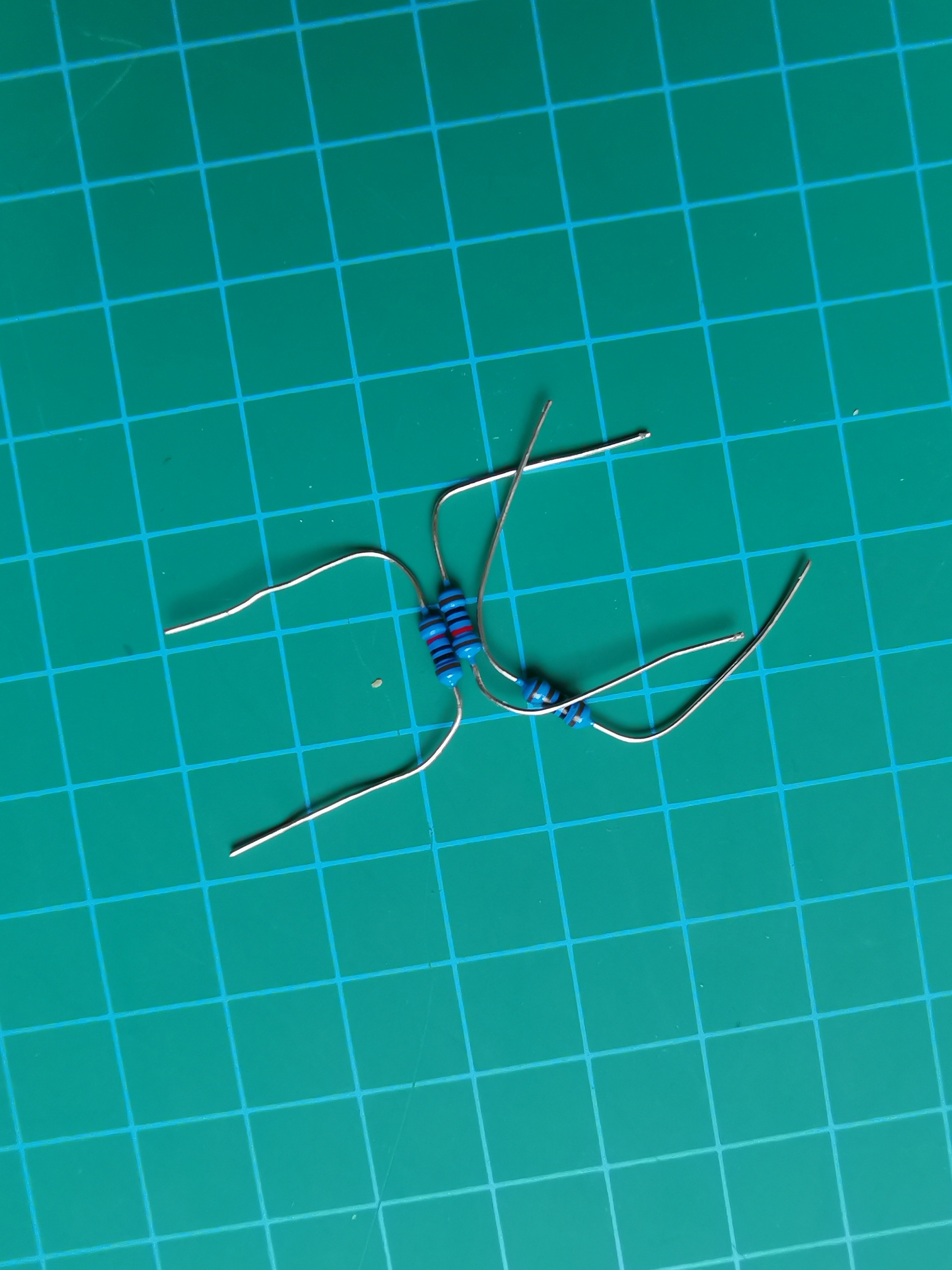
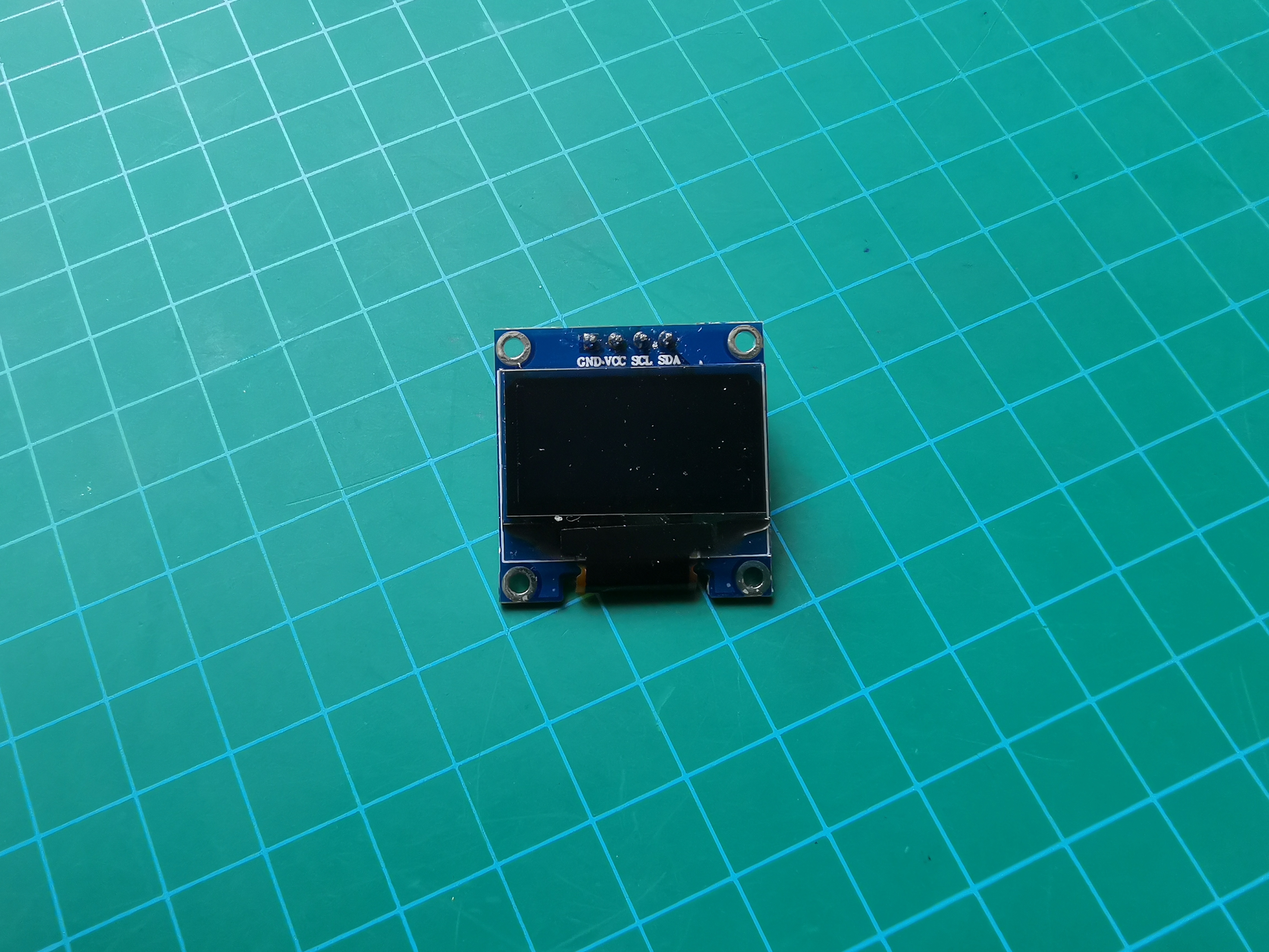
- one SSD1306 i2c OLED
- one DS3231 Breakout Board
- three Pushbuttons
- three 1 kilohm resistors
- sixteen male to male wires (or not if no prototyping and on a smaller form factor)
- one breadboard (or not if no prototyping and on a smaller form factor)
- oh yes, and one Arduino (all are fine, but in this example, it's an Arduino Uno)
Schematic
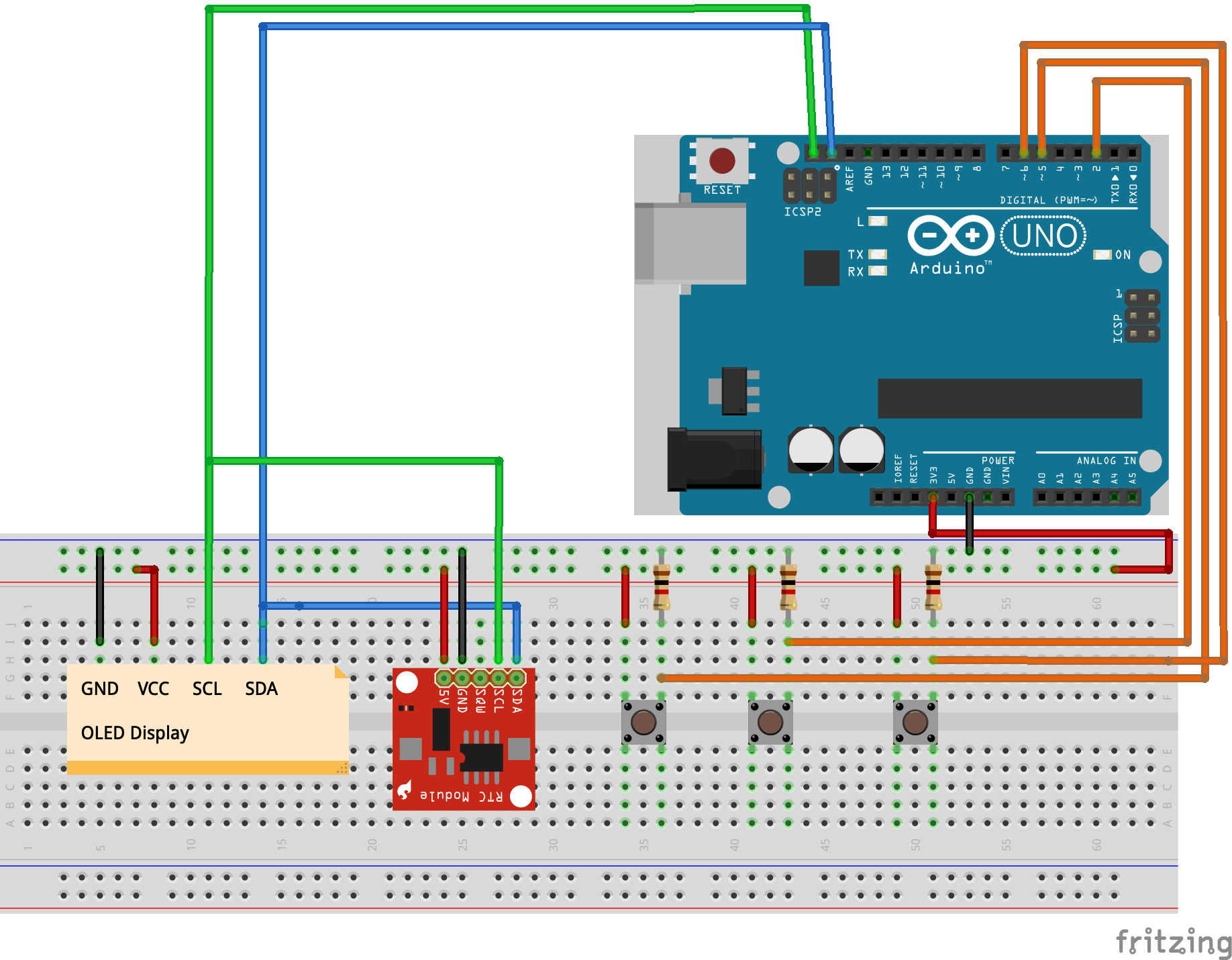
Here is the schematic, if you need it (wiring guide coming up!) (if you want to follow this, go ahead and skip to step 7)
Edit: sorry the schematic was wrong but now it is fixed
Wiring Guide: Power
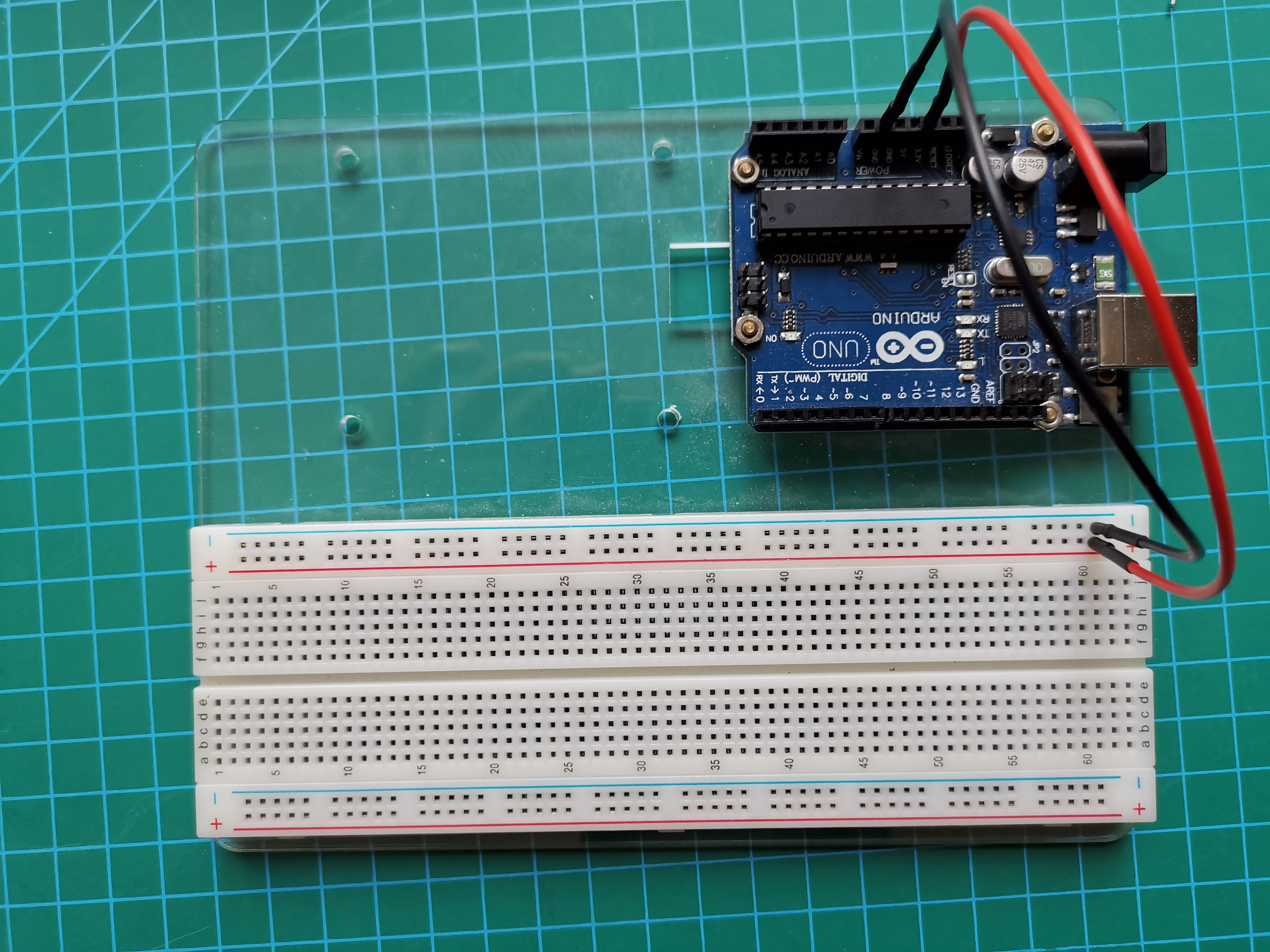
Simply Connect 3.3v and GND to the Power lines on the Breadboard
Wiring Guide: OLED
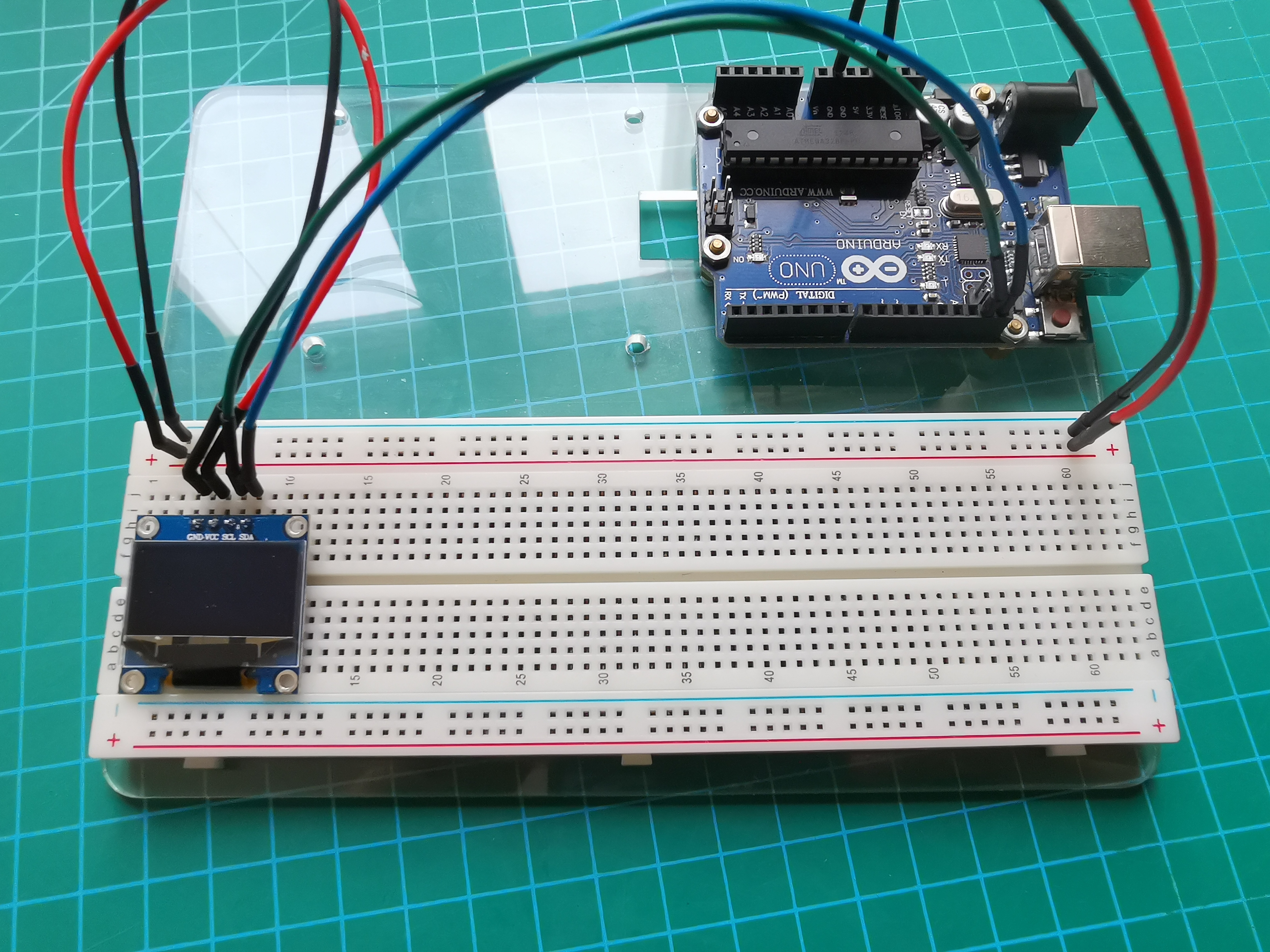
Connect the OLED to the Arduino, Following the Schematic (see, the wires even are the same color!)
Connect VCC to the 3.3v Power Rail
Connect GND to GND on the Power Rail
Connect SCL to A5 or dedicated SCL pin
Connect SDA to A4 or dedicated SDA pin
Wiring Guide: RTC Breakout Board
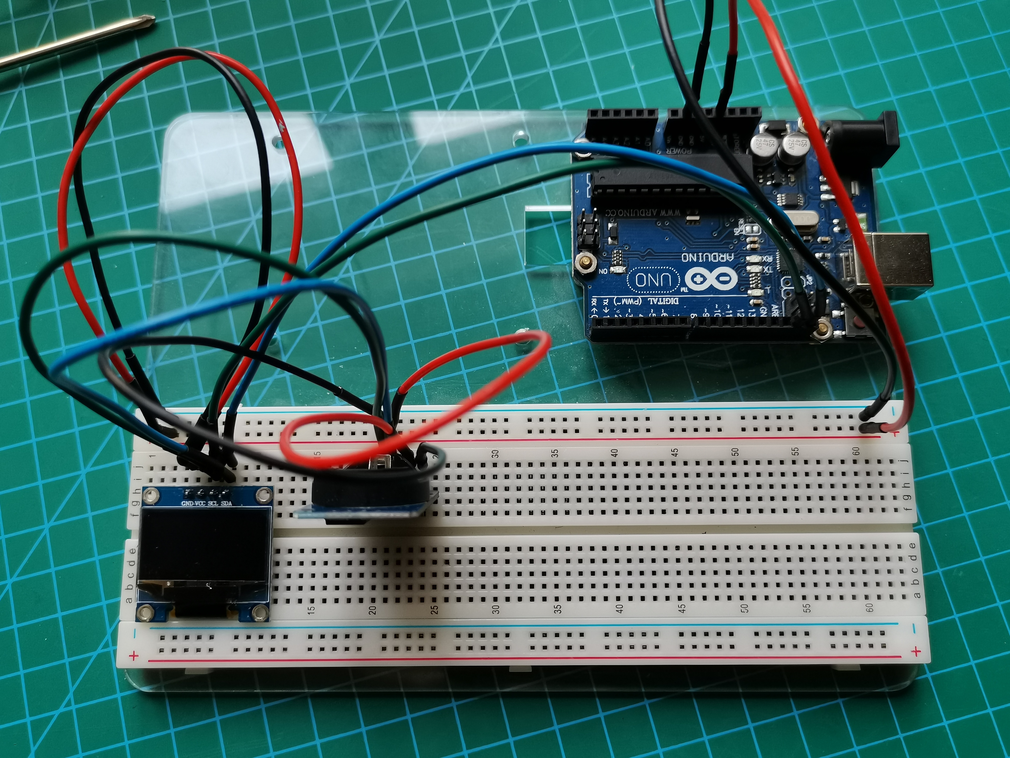
Again, Place the RTC on the breadboard and connect it to the Arduino
Connect VCC to the 3.3v Power Rail
Connect GND to GND on the Power Rail
Connect SCL to A5 or dedicated SCL pin
Connect SDA to A4 or dedicated SDA pin
(connections are same as OLED)
Wiring Guide: Pushbuttons
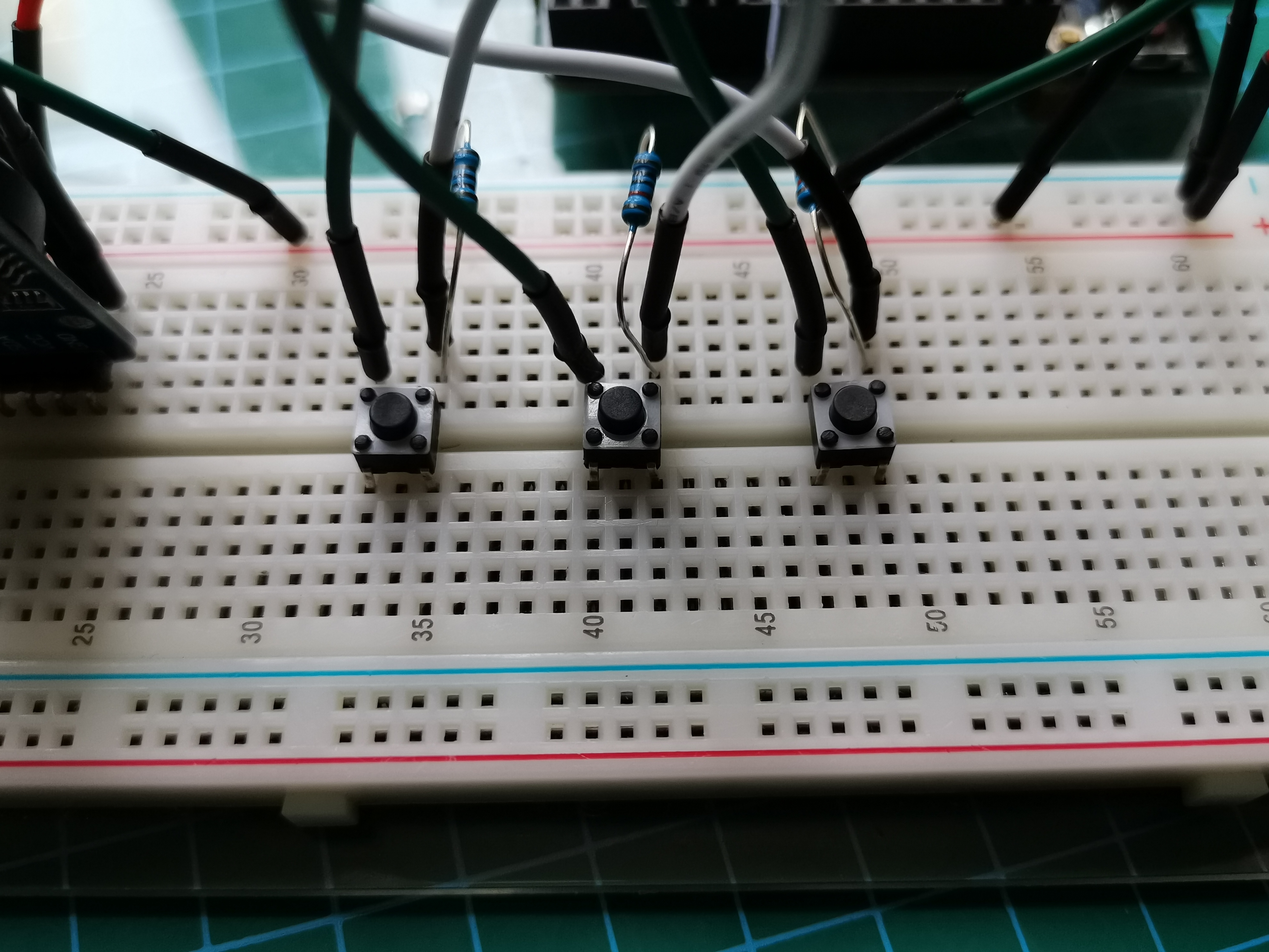
Connect as shown, and you're done! (well this is a simple watch, but not simple software)
Connect Midbutton from pin 2 to VCC on the Power Rail
10K resistor connected from pin 2 to GND on the Power Rail
Connect Upbutton from pin 5 to VCC on the Power Rail
10K resistor connected from pin 5 to GND on the Power Rail
Connect Dwnbutton from pin 6 to VCC on the Power Rail
10K resistor connected from pin 6 to GND on the Power Rail
The Code!
Here's the Code, have fun with your watch!
Libraries used:
Adafruit SSD 1306 Library: https://github.com/adafruit/Adafruit_SSD1306
Adafruit GFX Library: https://github.com/adafruit/Adafruit-GFX-Library
Wire Library: Should be builtin (it should have come with Arduino when you installed the program), but here it is anyway. https://www.resistorpark.com/content/Arduino_Libraries/wire.zip
DS3231 RTC library: http://rinkydinkelecronics.com/download.php?f=DS3231.zip
HELLO CYNTHIA
Downloads
Xtra Step: Extracting the Libraries (if You Know How, Skip This Step)
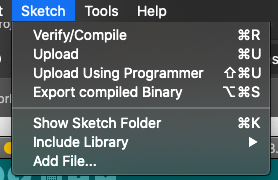

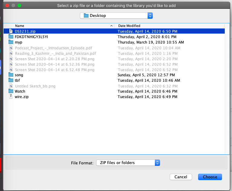
In the Menu Bar, Go to
Sketch >> Include Library >> Add .ZIP Library
and select the zip file through the popup window
How to Use Your Watch
Simply Use the Three Buttons as Interface buttons,
In the Watch Menu:
- The button connected to Pin 5 is Enter Menu
- The button connected to Pin 6 is Enter Menu
- The button connected to Pin 2 is Enter Menu
In the Menu:
- The button connected to Pin 5 is UP
- The button connected to Pin 6 is DOWN
- The button connected to Pin 2 is ENTER
In the Stopwatch:
- The button connected to Pin 5 is Start / Stop
- The button connected to Pin 6 is Reset
- The button connected to Pin 2 is Exit
In the Timer:
- The button connected to Pin 5 is Start / Reset&Stop
- The button connected to Pin 6 is Mode / Nothing
- The button connected to Pin 2 is Exit
In Set Time:
- The button connected to Pin 5 is (+ Time)
- The button connected to Pin 6 is ( - Time)
- The button connected to Pin 2 is Next / Exit
Further Steps
- Bluetooth Module With Notifications
- Less Variables - Very Messy Throughout the Code
- Minimize Watch (Arduino Nano, Standalone DS3231, PCB?)
- Sleep Functions to use less Power
Use these ideas to further develop this watch!
Please Vote & Support
Please Vote for Me in the Clocks Contest!
If you need help recreating this project, feel free to leave a comment down below or contact me at jiaronghu8@gmail.com
Also, Following & Liking is free