Arduino Based Egg Plotter
by vanroeyrien in Circuits > Arduino
21984 Views, 125 Favorites, 0 Comments
Arduino Based Egg Plotter
.jpg)

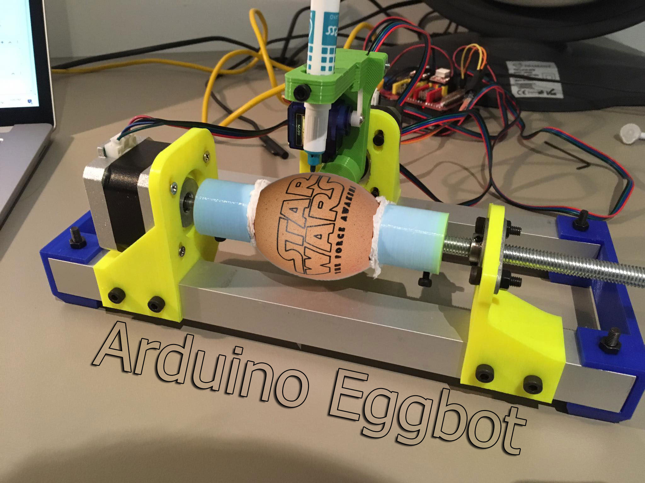
An Egg plotter is an art robot that can draw on spherical shaped objects such as eggs. You could also use this machine to draw on ping pong balls and golf balls.
You can use your imagination with the designs you put on it, you could for example make personalized eggs for Easter.
In this instructable we will not only show you how to make it, but we also created a step by step guide on how to properly use the machine.
I tried to explain this as easy as possible.
This might be the longest instructable you have ever seen/read but I just wanted to make sure that everyone can follow, no matter what their age might be.
The Design
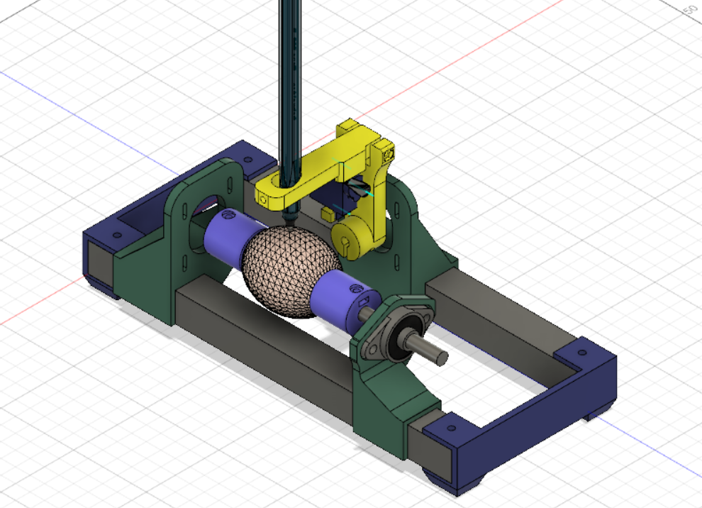
I have spended many hours in fusion 360 designing this thing. I was inspired by the EggBot Pro by EvilMadScientist. Their Eggbot is a well worked out piece of art, but the price is just ridiculous at 325 dollars. So I decided to take on the challenge and I tried to create a sub 100 dollar Eggbot.
I also tried to use as many parts as I had laying around, so if you see a weird choice of hardware, thats why. But if you are bothered by that, feel free to make a remix and share it with us.
What I want to mention is that my Pen Holding mechanism is based on Okmi's design. I did make some changes, but it looks almost the same.
I think that Autodesk Fusion 360 is the best software for creating these type of projects. It is not only free for students and hobbyists, but it is also well build. Everything just works like it should work. It does take a little bit of time to learn how to work with this software, but once you get the hang of it, it is as easy as it gets. I don't call myself a pro, but I am very happy with the result I got. When I have to explain this software to someone, I just call it Minecraft for adults.
For the few that are interested in the design, you can find it in the 3D-printing step.
Parts
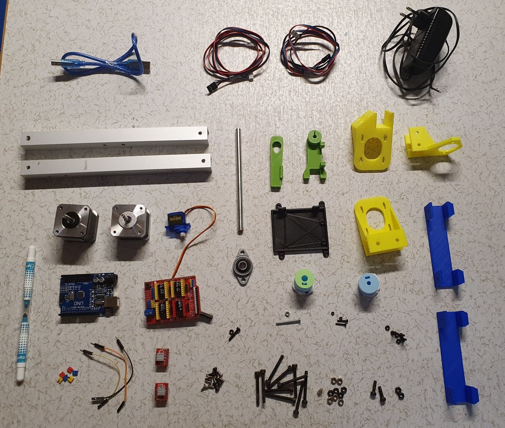
Mechanical components:
- Aluminium profile 20x20*250mm (2x)
- KLF08 Bearing (1x)
- Lead Screw 8mm * 150 (1x)
-
M2 12mm (2x)
-
M2 Nut (2x)
-
M3 30mm (2x)
-
M3 16mm (1x)
-
M3 12mm (1x)
-
M3 8mm (13x)
-
M3 Nut (7x)
-
M4 30mm (10x)
-
M4 Nut (10x)
-
Toilet paper, foam or bubble wrap (something that cushions the egg)
Electronics components:
- CNC shield (1x)
- Arduino Uno (1x)
- A4988 Stepper Driver (2x)
- Nema 17 Stepper Motor (2x)
- SG90 Micro Servo (1x)
- Jumpers (6)
- 12V 2A Power Supply (1x)
- Male to Female Jumper Wires (3x)
Tools:
3D Printing
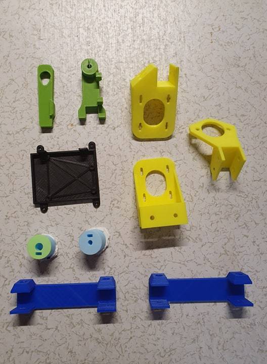
The 3D printed parts are very imported in this project, so make sure you use the right settings. The parts have to be strong enough so nothing bends or brakes and interferes with the quality of the image on our egg.
To start I want to talk about the filament you should use. I would recommend PLA because it is kind of bend resistant. PLA is not heat resistant, but there won't be much heat dissipated by this machine. You could use PETG that bends more and is harder to break, but I don't think this advantage is worth the extra money. So if you have some spare PETG, use that. If not, just buy cheap PLA.
The infill I used was 20% for every part. This is not considered super high, but it will get the job done. There won't be many vibration like in a CNC machine for example so I think 20% is just fine.
As my layer height, I used 0.2 mm. This doesn't really matter, but the lower you go, the better your print looks and also the longer your print time will take.
As my temperature, I used 200° C on my hot end and my bed was 55° C. This part depends on the type of material that you use.
Supports? For some parts you may need to use some sort of support material, but I think for 70% of the parts, you can just avoid them by orienting them in a proper way.
Also make sure you keep the parts safe and be careful with them. Some of them are very easy to break.
So short summary: use PLA and 20% infill.
Preparing the Pen Holder Part
The first part that we will assemble is the the smallest and trickiest part to build. It is pretty small so if you have big hands, good luck! This part will hold the pen, make the pen go up and down and later on we will attach a second motor that will make the pen rotate. This is actually a crucial part of the machine because this the part that might create a lot of if not attached correctly. But don't worry it is actually pretty easy and I have token a lot of pictures. I also added a parts list for this specific part and split it up into multiple steps:
- SG90 Micro servo with accessories
- 1* M3 30mm
- 1* M3 12mm
- 2* M3 nut
- 2* M2 12mm
- 2* M2 nut
- Pen_Holder_Bottom (3D printed)
- Pen_Holder_Top (3D printed)
Step 1: Create the hinge
The hinge that will lift up the pen is created by the M3 30mm screw. Just line the parts up so you can see trough the hole and push the screw in and attach it on the other side with the M3 nut.


Step 2: Preparing the Servo
We will need to attach a servo horn to the servo. This is the small white plastic part. Make sure you use the right one like in the images. The horn should come with your servo as well as the screw that attaches the horn to the servo.


Step 3: Attach the servo to the Scissor parts
Now that our servo is ready, we can attach it to the Pen Holder. Just line up the servo like in the images and use the M2 12mm screws and nuts to keep it in place.


Step 4: Add the pen holding screw
On the top of the part, there is a hole specially made for a nut. Place the nut in there and screw in the last M3 12mm screw from the back. This is a mechanism that will clamp our pen so it doesn't move when we are printing something onto our egg.


Congrats, your first part is finished now! Now you can move on to the next step.
Attaching Stepper Motors
In this step, we are going to attach the stepper motors to their correct holders. The stepper motors will make the egg rotate and make the pen move to the right and left. We will also add the part that holds the bearing which will make the egg move even smoother.
For this step you will need:
- 10* M3 8mm
- 3* M3 16mm
- 5* M3 nut
- 2* Nema 17 Stepper Motor
- 8mm Lead Screw
- YZ_Stepper_Holder (3D Printed)
- X_Stepper_Holder (3D Printed)
- KLF08_Holder (3D Printed)
- Egg_Holder_5mm (3D Printed)
- Egg_Holder_8mm (3D Printed)
Step 1: Attach XY-Stepper Motor
The Stepper motor that will control the YZ planes has to attached to the 3D Printed YZ_Stepper_Holder. I designed the part so the height of the stepper motor can be adjusted. I recommend to put them in the middle and adjust it later on if neccesary. You have to use 4* M3 8mm screws to attach the stepper motor and make sure that the connector (white piece of stepper motor) is facing upwards.


Step 2: Attach Y-Axis
The hinge part, pen holder or Z-axis can now be attached to this Stepper Motor by using a M3 Xmm screw and an M3 nut. The screw and nut will act like a little clamp and hold the pen holder in place. Make sure there is a little gap between in my case the yellow and green part. The pen holder needs to move smoothly withouth touching anything.

Step 3: Attach X-Stepper Motor
The Stepper motor that will control the X plane has to attached to the 3D Printed X_Stepper_Holder. I designed the part so the height of the stepper motor can be adjusted. I recommend to put them in the middle and adjust it later on if neccesary. You have to use 4* M3 8mm screws to attach the stepper motor and make sure that the connector (white piece of stepper motor) is facing upwards.


Step 4: Attach Egg Holder
To keep our egg in place we will attach an egg holder directly to the X-Stepper motor. This pretty straight forward, just put the M3 nut inside the rectangular hole and screw in the M3 Xmm in the round hole and it should keep the 3D Printed Egg_Holder_5mm in place. Try to push the stepper motor as far as you can into the egg holder.

Step 5: Attach Bearing
The KLF08 bearing has to be attached to the 3D Printed KLF08_Holder. Its held in place by 2* M3 8mm screws and 2* M3 nuts. Make sure that the circle that has 2 tiny tiny screws in it is facing to the flat side of the part. The picture explains this.


Step 6: Attach 2nd Egg Holder
The second Egg Holder is the 3D Printed Egg_Holder_8mm part that will be attached to the bearing. Take the 8mm Lead screw and slide the Egg Holder into it. Now put the M3 nut again in the rectangular hole and screw the M3 Xmm into the round hole. After that you can slide the rod into the bearing and use the little screws of the bearing to keep the Egg Holder in place. The length between the Egg Holder and bearing will be different for every egg, so you have to unscrew them every time you put a new egg in the machine. For clarity I putted my allen wrench in one of the screws.


Preparing the Base
All of our parts will be attached to the base that is reinforced by 2 pieces of square aluminum tubes. Those tubes not only make the machine more rigid, but it also looks and feels more expensive. Be carefull with the 3D printed base plates, they are very fragile. This step is also splitten up into multiple very small steps
For this step you will need:
- 2* Aluminium profiles
- 2* 3D printed base plate
- 4* M4 30mm
- 4* M4 Nut
- Base_Plate_Right (3D Printed)
- Base_Plate_Left (3D Printed)
- Drill
- 4.5mm Drill bit
Step 1: Aline everything up
Slide the aluminium profiles in the baseplates, make sure everything is lined up perfectly, because if not, your base will wobble.


Step 2: Mark the holes for the drill
The aluminium base is pretty loose right now, so we need to attach them using screws. Thats why we need holes in our aluminium profiles, so the screws can fit through them. Because measuring everything is a boring and very time consuming proces, we will just use the 3D printed base plate as our measurement. Take a pen and mark the holes, so we can drill them later on. Make sure to mark both the points on the bottom as well as the top. It is easier to drill from both sides instead of drilling them both in one go.


Step 3: Drill the holes
Now that we have marked the holes, it's time to drill them. The size of the drillbit that you need is 4.5 mm. Also make sure that the drillbit that you use is specialy made for metals like aluminium, this will make the job so much easier. You have to drill through all the 8 holes that we just marked.


Step 4: Insert the screws
Now our holes are ready and we can start to attach everything strongly togheter. Use the M4 30mm screws and nuts. Make sure to place the nuts on the top because I made a special hole to hide the round screw cap on the bottom of the 3D printed base plates.


Now that the base of your machine is finished, you can give it a little strenght test. You can push on the base and it should feel very solid. If not, try to fasten the screws, check wheter the holes are perfect or not.
To this part we will attach everything in a couple of steps, you can put it aside and get prepared for the next step!
Attach Everything to the Base
Now that we have created the base as well as all of the parts, we can start attaching everything to the base.
For this step you will need:
- 6* M4 30mm
- 6* M4 Nut
- All the other parts that you've created so far.
- Drill
- 4.5mm Drill bit
Step 1: Put the Parts in the Right Place
Look at the picture and place your parts in the excact same spots. The green pen holder has to be in the middle of the 2 egg holders.

Step 2: Mark the holes
Mark all the 12 holes of the part that touch the base plate so we can drill them later on. Each part has 4 holes.
 Step 3: Drill the holes
Use your 4.5mm drill bit again to drill out all the marked holes.

Step 4: Attach the parts again
Attach the parts again to their place all using the M4 30mm screws and M4 nuts. Some parts have inserts for the M4 nuts, so use them. You can recognise them by the hexagonic shape.


Electronics
Now that all the 'Hardware' is ready, we can move onto the electronics. They make the motors actually move and in the next steps we will configure the software for it.
You'll need the following
- CNC shield
- Arduino Uno
- 2* A4988 Stepper Driver
- 6* Jumpers
- 12V 2A Power Supply
- 3* Male to Female Jumper Wires
- 3* M3 8mm
Step 1: Attach the Arduino to a Base
Put the arduino into the little base and screw it in place using three M3 8mm screws.


Step 2: Attach CNC shield
Just lign up the pins of the arduino and CNC shield and put some pressure on top to secure it.


Step 3: Jumpers
I actually forgot to take a picture of this but you have to put jumper on the 6 pins like in the image. Colors don't matter btw. You only have to put them on the X and Y spots that are marked on the CNC shield.


Step 4: Stepper Motor Drivers
Plug in the A4988 Steppers in in the CNC shield and check that you have putten them in the right orientation, look at the picture for reference.


Step 5: Servo
The Servo attachment is a little bit tricky, because this board wasn't designed for one. So the servo has 3 colors: black/brown represents GND, orange/red is +5V and the yellow or sometimes white wire is data. You have to plug them into their right and for that you can look at the image. You have to plug first the male side of the jumper wires into the servo cable and then stick the female ends into their correct place on the CNC shield. If the wires are very loose, apply some electrical tape or even duck tape.


Step 6: Wiring the Stepper Motors
Take the wires that came with the stepper motors and plug them both into the stepper motor itself and the CNC shield.

 Step 7: Power Supply
Cut of the end of the power supply with a scissor and strip the 2 cables. Now attach the GND wire to - and the 5V wire to +. The 5V wire has white stripes on it.


Now you can plug in the power supply to the wall outlet because we are going to start with the electronics.
Software
The process of getting an image on our eggbot goes the following. Before you start, make sure you have downloaded the Arduino IDE.
https://www.arduino.cc/en/main/software
The install is pretty straight forward, so no explaining needed.
1. Create a drawing
In Inkscape you can design the drawing that you want on your egg, In this instructable I am not going to talk on how to use it, so Its essential to follow a small beginners tutorial on inkScape.
2. Create the GCODE
We will create a code that tells the Eggbot to move its motors in the right way, so we end up with an image on the egg. We will use a web based software called "JScut".
3. Send the GCODE to the Eggbot
In another software called CNCjs we will send the GCODE to our eggbot.
4. Watch how the machine drawes on the egg
On our Eggbot we will upload a program called GRBL, this is mostly used in CNC machines, but we will slightly modify it to work with our Eggbot. This software reads the gcode and converts it to movements in the motors. But once this is on the Arduino, you can lay back and watch how your egg is getting a nice design.
Uploading GRBL to the Arduino
Like I said earlier, GRBL will convert the GCODE to movements in the motor. But because GRBL is actually made for Stepper Motors only and our Z-axis is done with a servo, we have to modify it. This part is a step by step guide on how to download, modify and upload GRBL.
Step 1:
Go to this site: https://github.com/grbl/grbl and click on clone or download, then click download zip.

Step 2:
Once it is installed you can open the zip file, I use winRAR you can also download it. In that file search for the folder grbl and extract that folder to your desktop.

Step 3:
Now open arduino and go to Sketch --> Include library --> Add .ZIP Library. Now locate the grbl folder and click open. The folder should be located on your desktop.

Step 4:
Once that is done, were going to once again download a file. This file will modify GRBL so it works with a servo motor. Go to https://github.com/bdring/Grbl_Pen_Servo and once again click clone or download followed by download zip. Now open that file and head over into the 'grbl' folder. Copy all the files that are in that folder.

Step 5:
After you've done that go to File Explorer --> Documents --> Arduino --> Libraries --> grbl and paste all the files in here. If there is a popup just choose 'Replace the files in the destination'.

Step 6:
Restart the Arduino IDE and plug in the usb cable of the Eggbot into your pc. After you've restarted your Arduino IDE go to File --> Examples --> grbl --> grblUpload.

Step 6:
Now go to Tools --> Board and choose 'Arduino Uno'. Now go again to Tools --> Port and choose the COM port that your arduino is connected to.
 Step 7:
Click on upload, the button on the left top corner (arrow to the right) and after a minute you should see on the left bottom a message saying 'Done uploading.'.
Configure CNCjs
CNCjs is the software that we can use to control the machine and send GCODE to the machine. So in this part we will configure CNCjs.
Step 1:
Download CNCjs: https://github.com/cncjs/cncjs/releases
Scroll down and install the file that is marked in the image below.

Step 2:
Open CNCjs and in the upper left corner select the COM port of your arduino followed by a push on the 'Open' button.
Now the console should appear right underneath the 'Open' button.
Step 3:
In the console you have to write a total of 6 commands, these will make sure that if the machine is asked to move 1mm it actually moves 1mm instead of 3mm for example. You have to press enter after each command!
- $100 = 40
- $101 = 40
- $110 = 600
- $111 = 600
- $120 = 40
- $121 = 40

CNCjs is now properly installed and setten up.
InkScape
InkScape is the program that you can use to make your design, you can if you want to also use Fusion 360. I am not going to teach you how InkScape works, but I did find a nice tutorial playlist on it so here it is.
You can download inkScape here: https://inkscape.org/release/inkscape-1.0/
After you've installed inkScape, you can go ahead and open it. Before you can start designing, we need to give our sketch the right dimensions. The dimensions of the sketch should be 20mm x 80mm. We will create a template for these dimensions, so you only have to enter in the dimensions once.
You can create the template by selecting File and then Document Properties. In here change the width to 20mm and the height to 80mm.

Now go to File then Save As and save it in this folder C:\Program Files\Inkscape\share\templates. Don't forget to give the file a name, I called mine EggTemplate.
Once saved, restart Inkscape and go to the main menu. Select File and then New from template... and then select EggTemplate or the name that you chose for the template. Now you can start designing your egg.
I just designed a fast and simple text saying Hello in my language which is Dutch for demonstration purposes
Once you are done with your design, go to File followed by Save As and save your file somewhere on your computer. You have to save it as a *.svg file.
Design to GCODE
Right now we have a *.svg file, but our arduino can only take *.gcode files, so we are going to convert our *.svg file to a *.gcode file using a web based program called "jscut".
This is the link to the website: http://jscut.org/jscut.html.
You can go ahead and click Open SVG and then select local and locate the *.svg file that you have just created. Now click on every object so they become blue. Go ahead and click on make all mm and change the Diameter to 0.2 mm. After that click on Create Operation and then click on Zero Center. And Last but not least click on save gcode and save the file somewhere on your pc.

Mounting the Egg
Now go ahead and place the in the Eggbot by loosening the 2 screws on the KLF08 bearing. The picture shows the screws I am talking about because there is an allen wrench in it. Also attach the pen to the pen holder, loosening up the screw, place the pen inside, retighten the screw again. When the servo is moved up, the pen should not be able to touch the pen, but when its moved down, the pen has to touch the egg. So you have to guess a little bit and adjust the height now and then.


I decided to put some toilet paper between the egg and the egg holder to give the egg some cushioning. This seems to help and I would highly recommend to do the same thing.
Also make sure the pen is in the middle of the egg, we start printing in the middle so if move the pen too far to the right, the pen will bump into the machine and might create damage. So make sure the pen is in the middle.
Uploading the GCODE
This is the last step, plug in the power cable and also the usb cable to the computer. Open CNCjs and click on Open. After that click on upload G-code and select the *.gcode file we have just created. After that click on the run button. And the machine should start printing.

Here is a picture of my machine printing the simple text design.
Designs
I haven't had the time to create lots of cool designs, because I have exams...
So I decided to give you some design ideas that other people already have created (using different machines) and you can recreate using this machine. I will eventually show in this step my own designs, but that will only happen after 2 weeks after my exams. I already gave a link to the author of the designs.

by jjrobots.
Problem Solving
If there is something not clear, use the comments to let me know and let me help you. I also added this step that might help you further with some of the most common problems with the machine. Already recognized problems can be found here.
Image on egg is mirrored.
Rotate the connection of the Y-Stepper on the CNC-shield.
Egg is loose.
Clamp the egg even better in its holder.
Pen is not writing on egg.
Use a pen that is heavier and has a bigger point