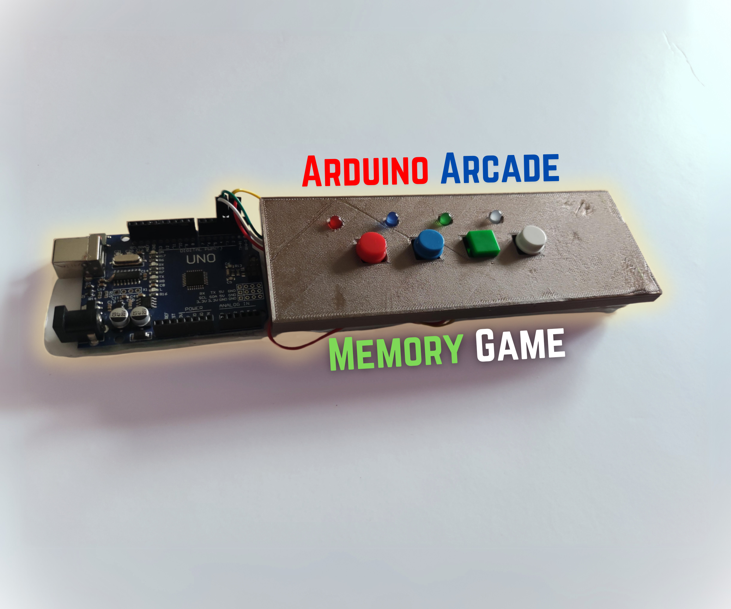
Arduino Arcade Memory Game
 (2).png)
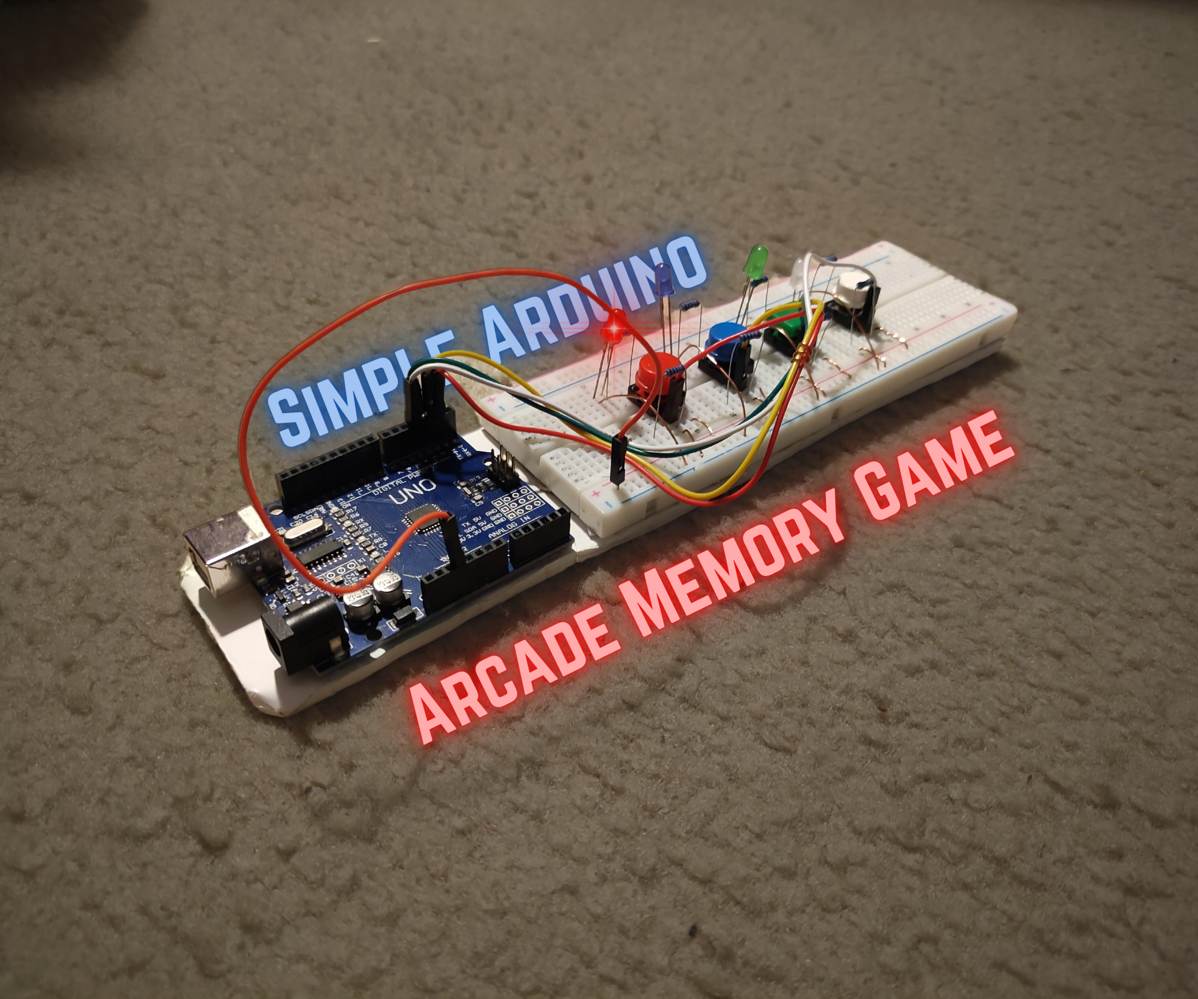
Welcome, fellow Autodesk Instructables and Arduino enthusiasts! If you're ready for a thrilling journey into the realm of interactive gaming, you've come to the right place. Today, we'll be delving into the fascinating world of Arduino programming to create a captivating Memory Arcade Game. This game is not just about lights and buttons; it's a dynamic and entertaining experience that challenges your memory skills in a fun, arcade-style setting. In this Instructable, we'll guide you step-by-step through the process of building your own Arduino Memory Arcade Game and how you can assembly and program it to function consistently.
Supplies
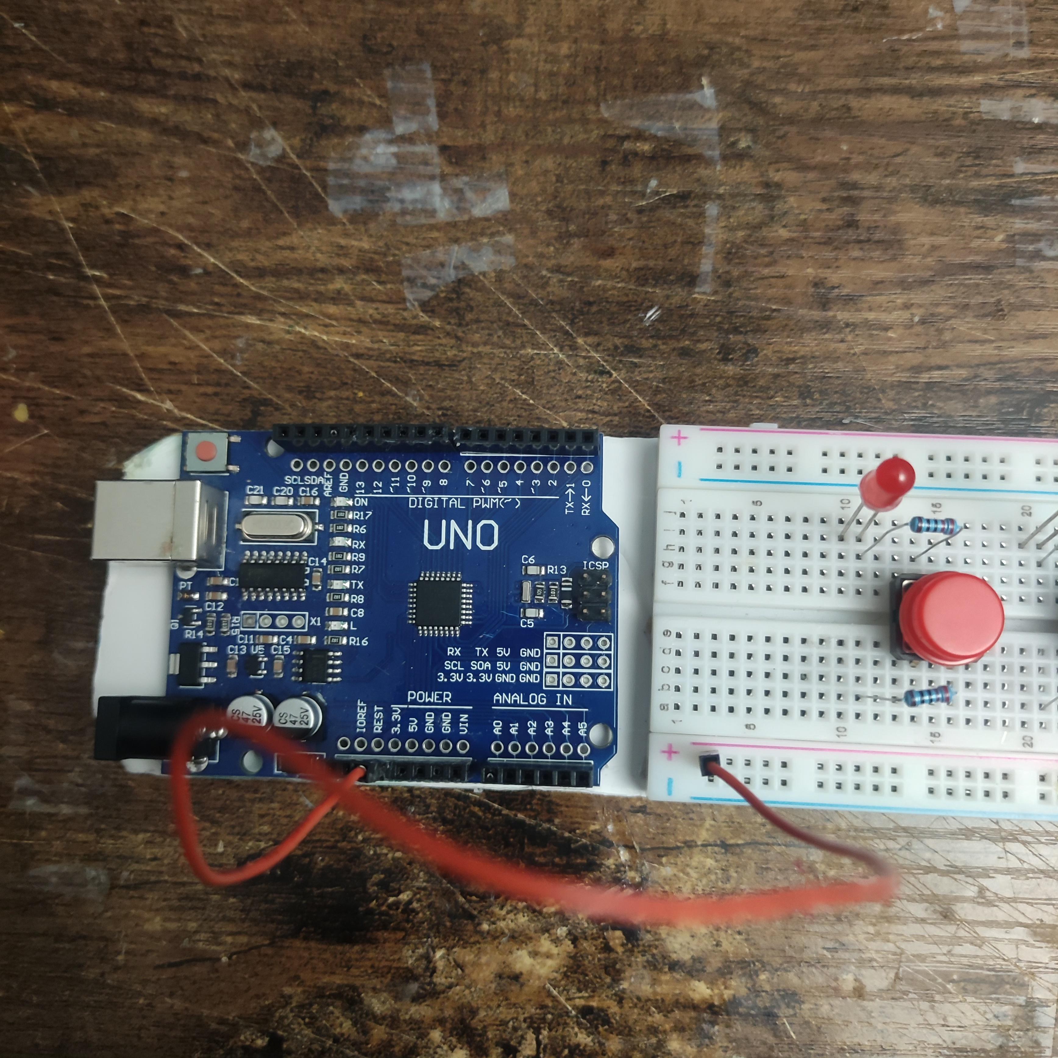
- Arduino Uno
- Arduino Uno USB-A cable
- Breadboard
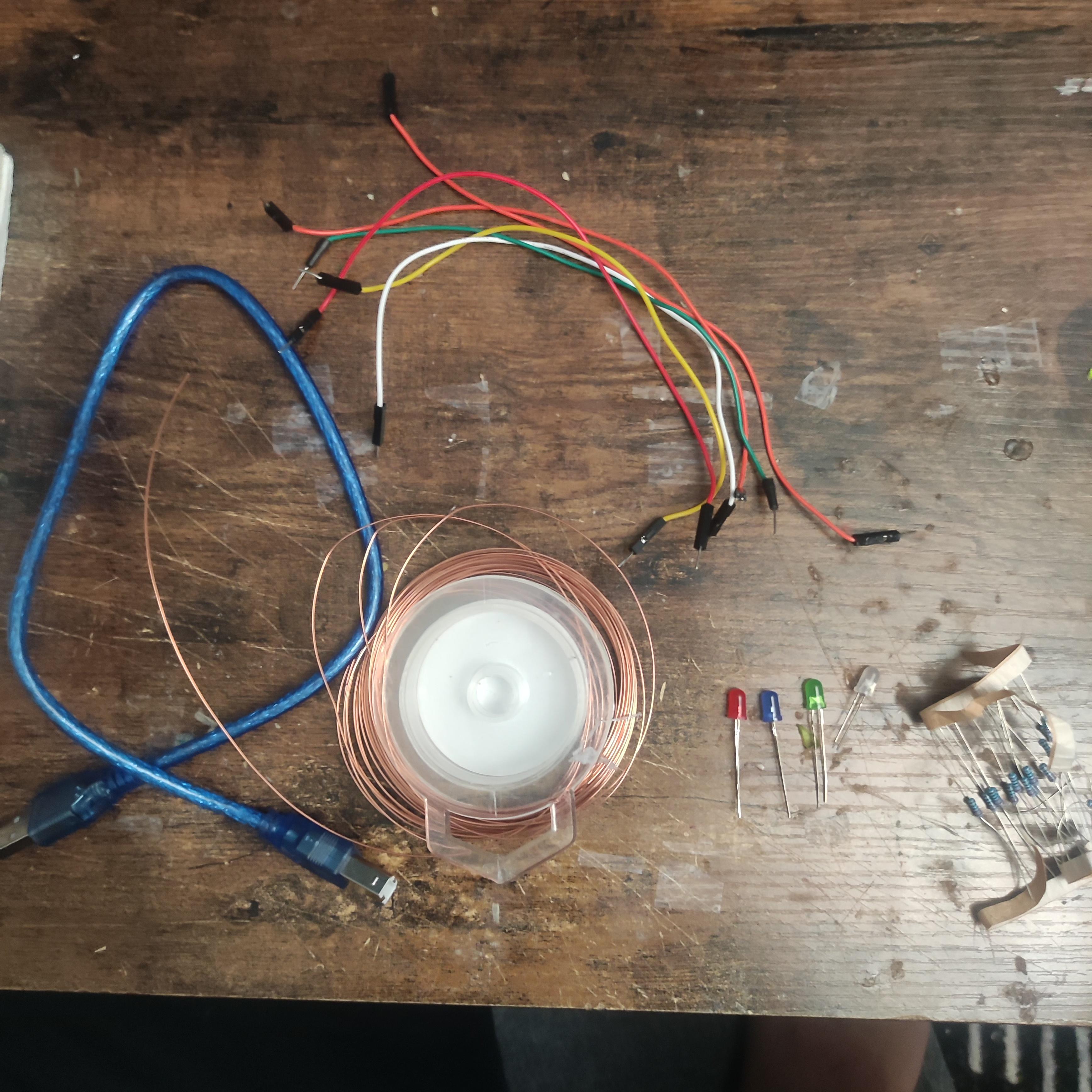
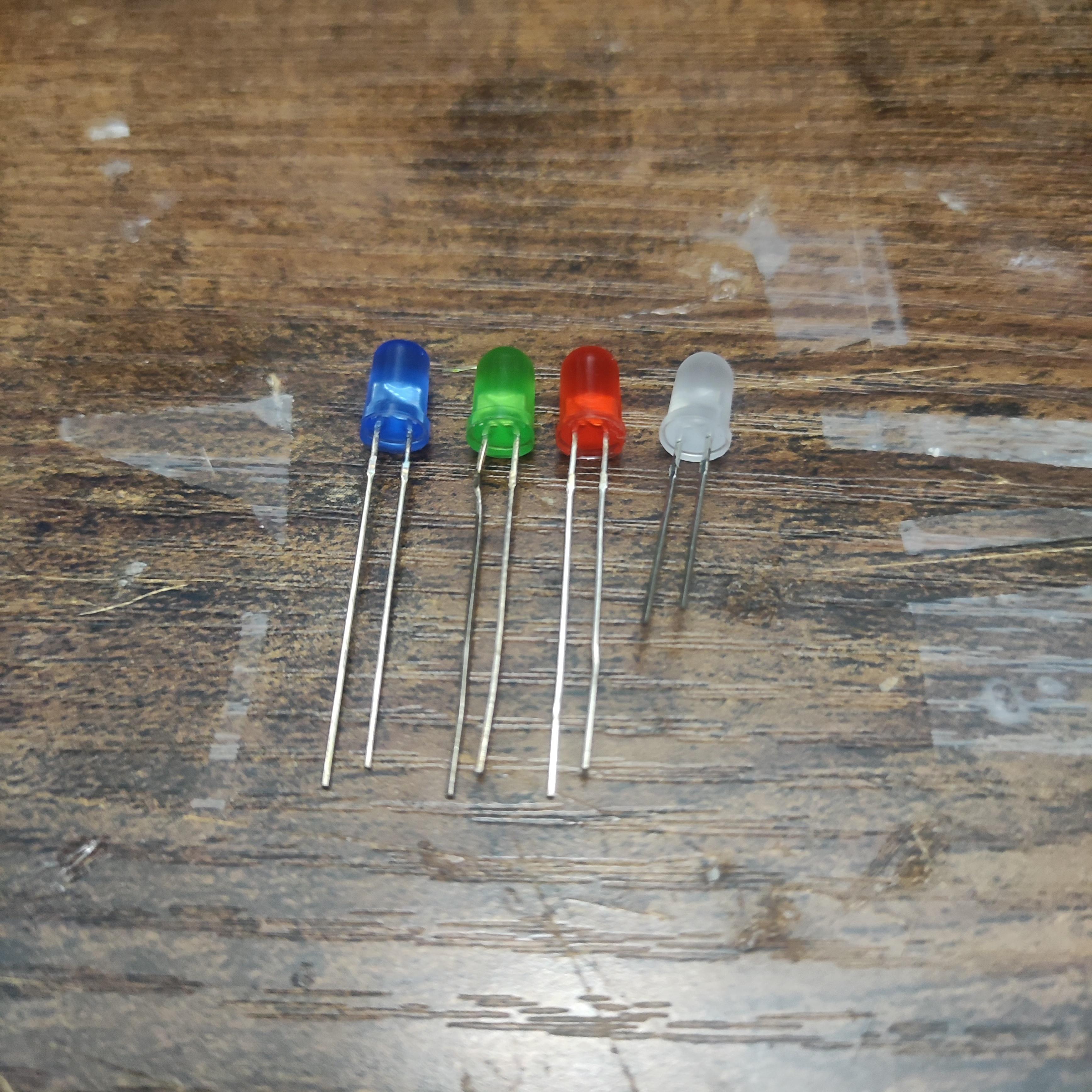
- 4 LEDs (Red, Green, Blue, White)
- Jumper Wires (Male: Male)
- Copper Wire
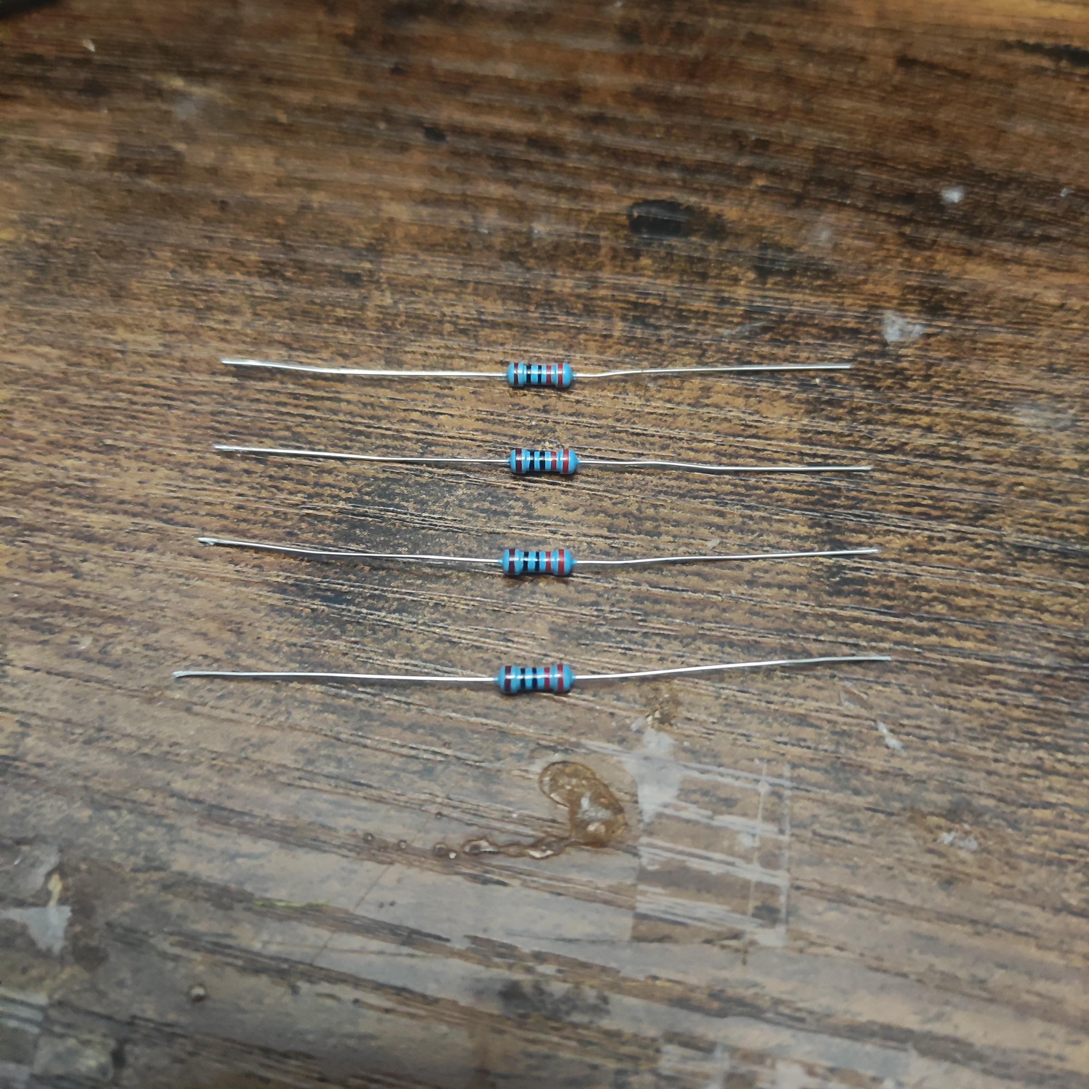
- 4 220 Ohm Resistors
- 4 Buttons
- Optional: 4 Button Covers
Optional: 3D Printer for the casing
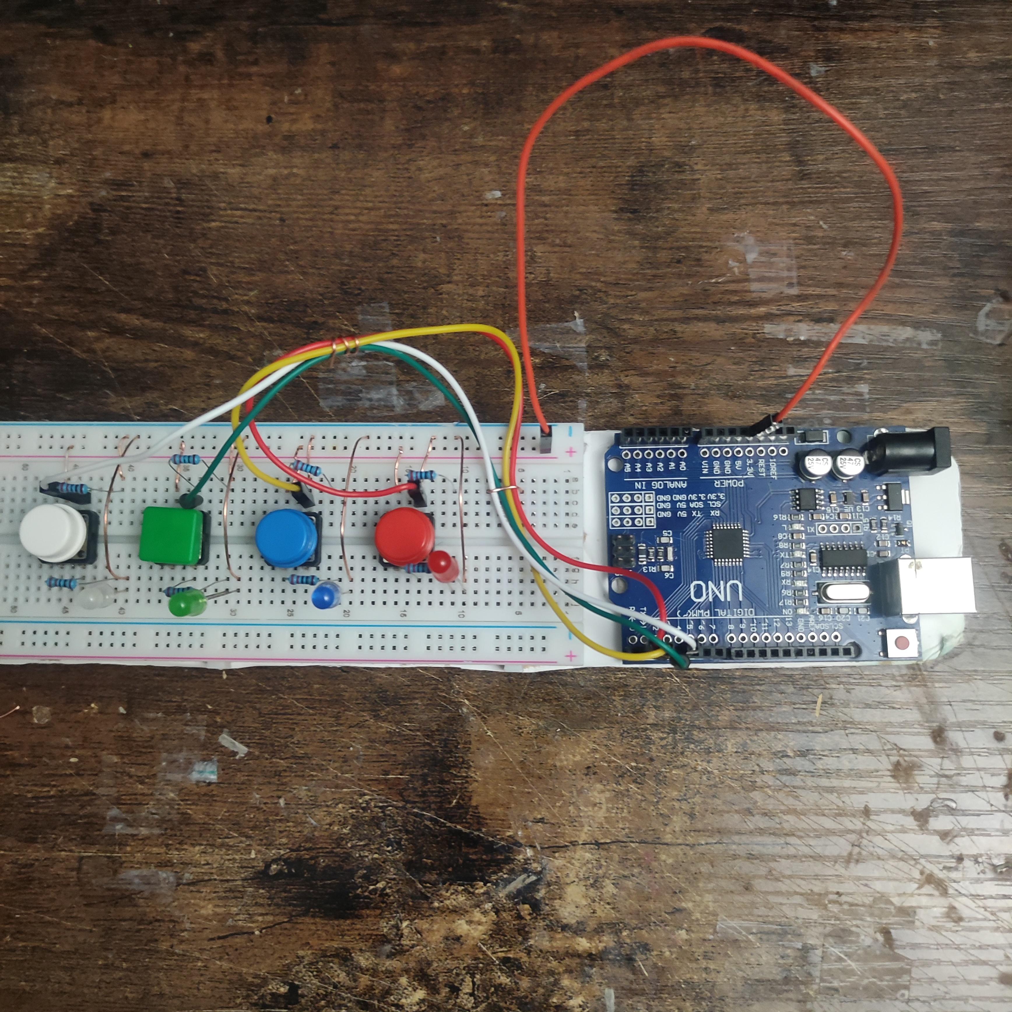
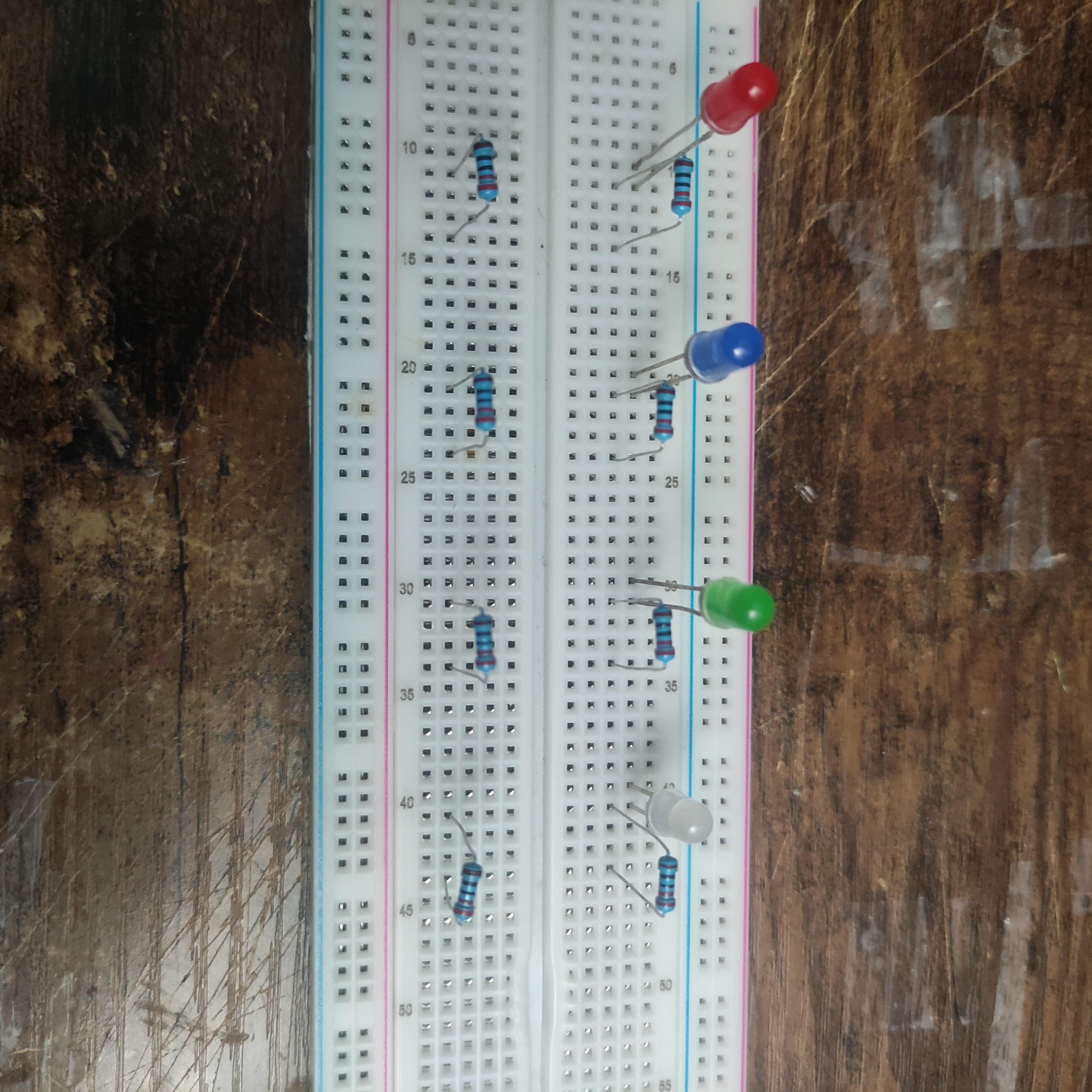
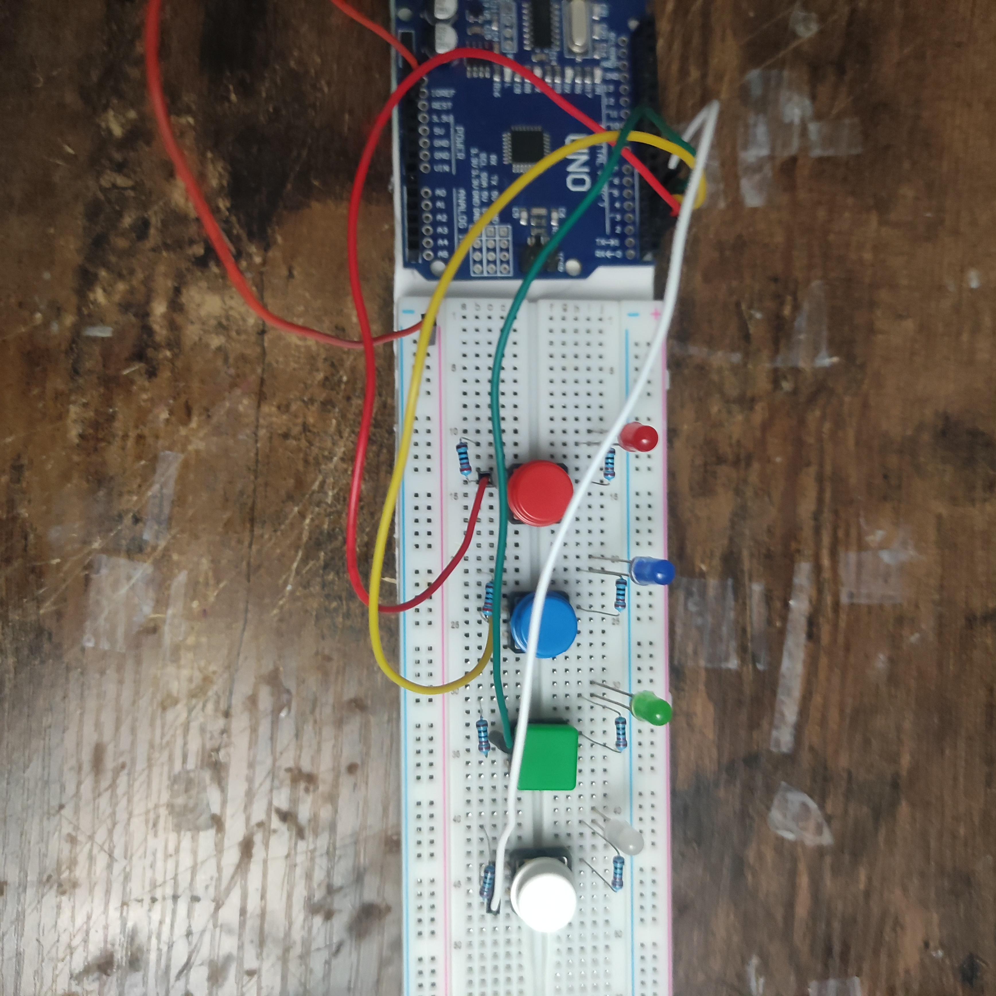
Setting Up LEDs and Resistors
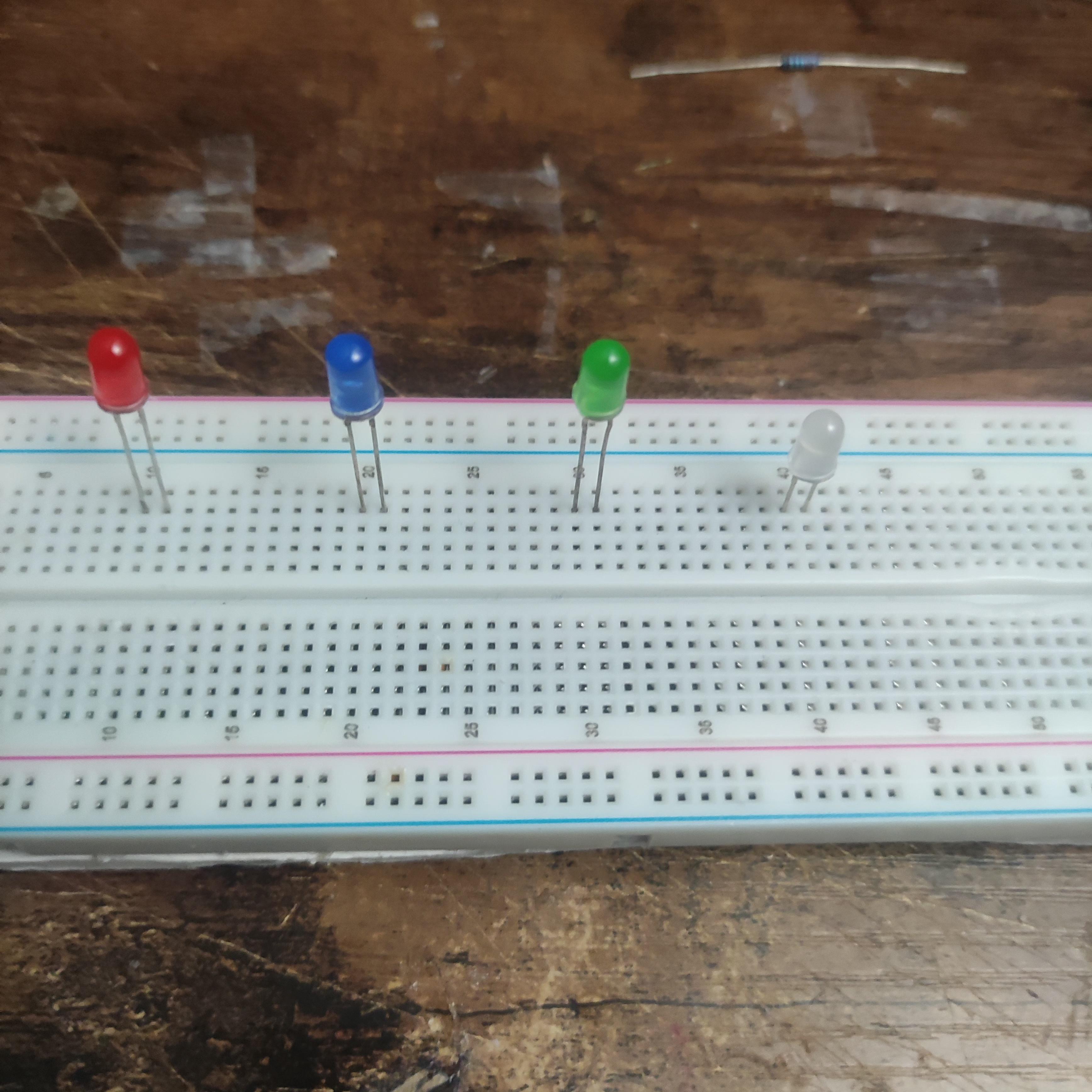

- Take your 4 LEDs and organize them sequentially
- Place one LED at every 10th slot on the Breadboard
- Ensure that the Positive Terminal (+) of the LED is to the right for EVERY LED
- Add 220 Ohm resistor one slot below where the Positive LED Terminal is connected
- There are no terminals on a resistor, so it does not matter which way you put it
Refer to the diagram above to ensure that your breadboard is laid out correctly.
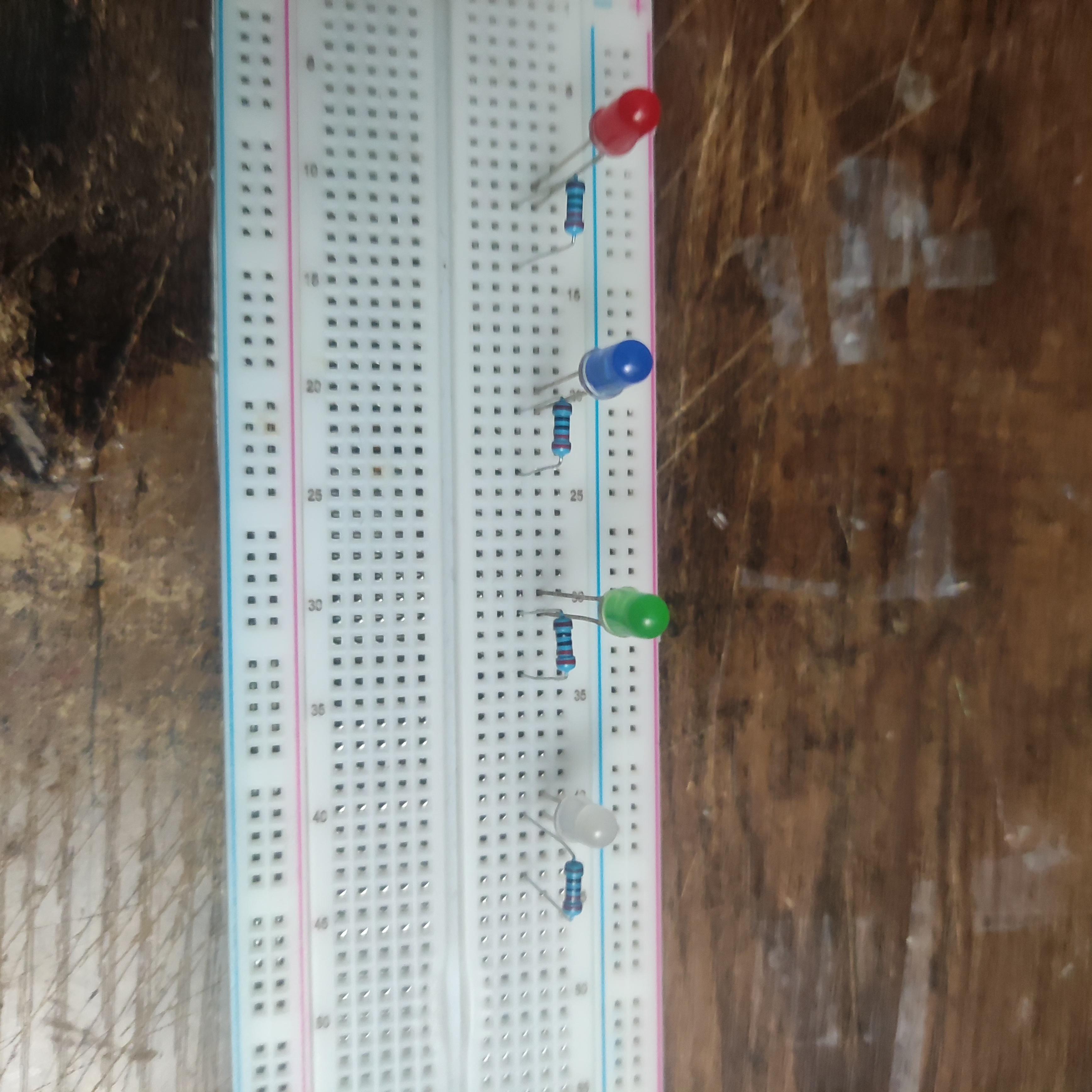
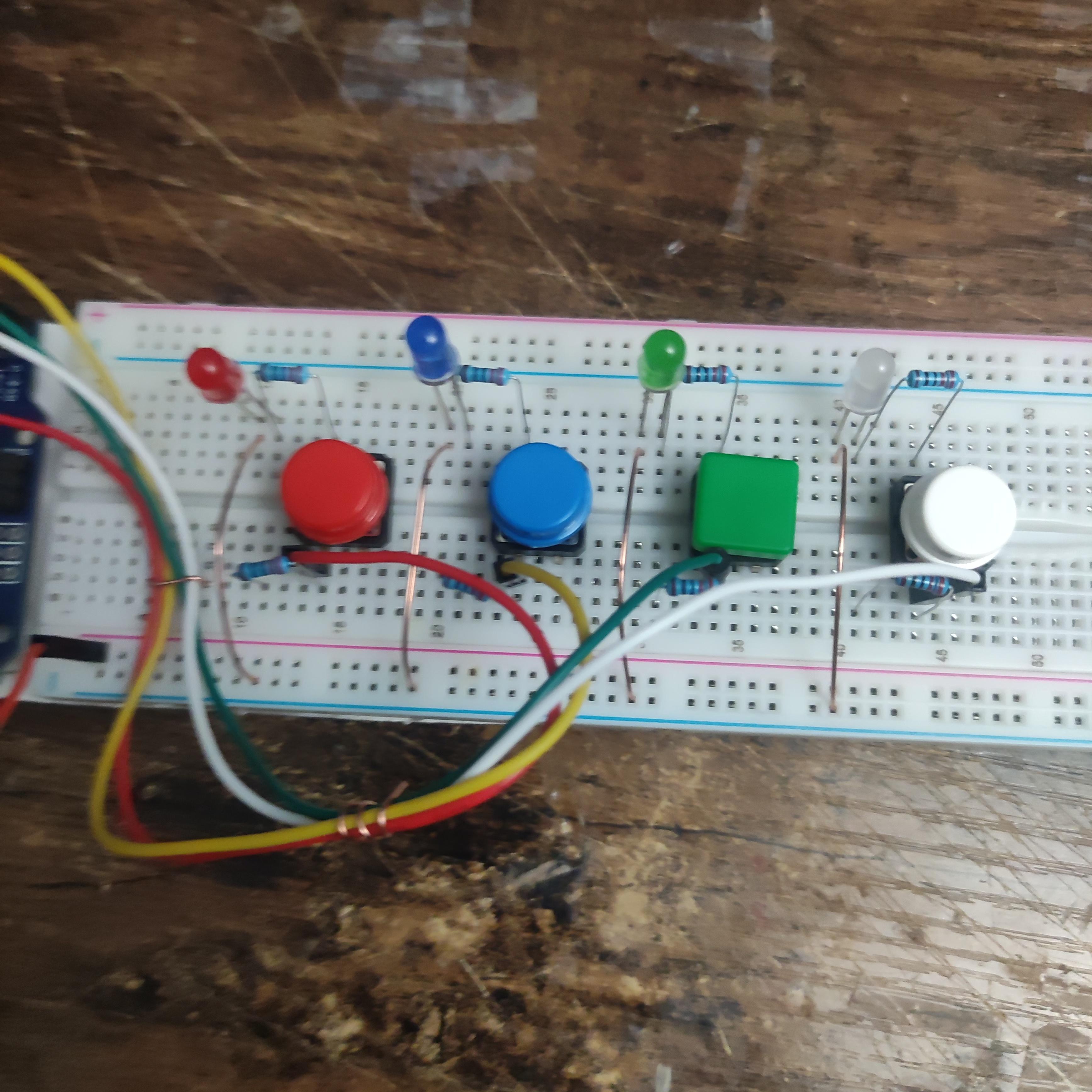
Adding Resistors and Buttons
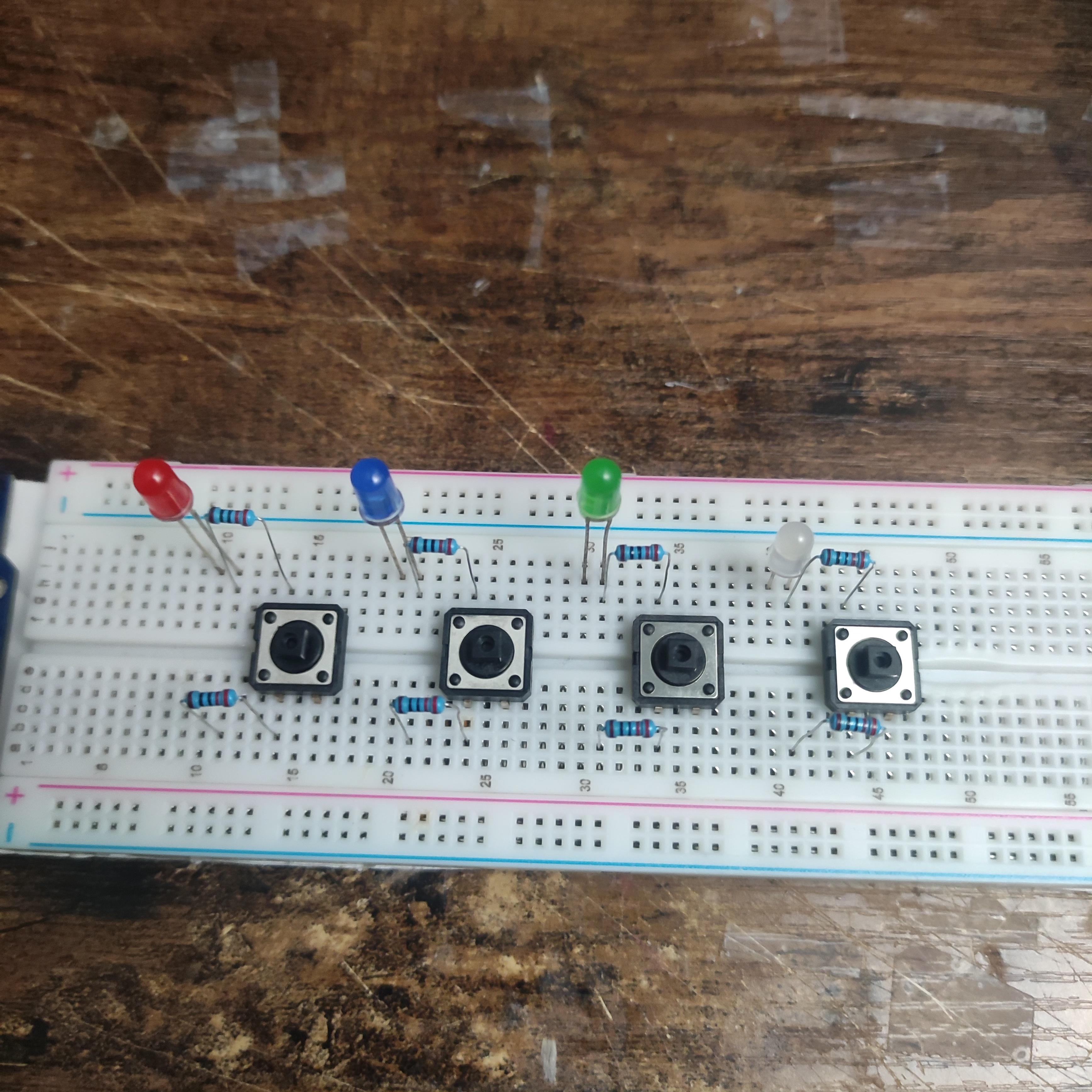
- Now, we need to add more resistors on the bottom of the breadboard for the buttons that we will be adding
- Take 4 more 220 Ohm resistors and place them in the bottom slot of the breadboard in-line with the resistors placed above
- Refer to the included diagram to ensure that you have placed the resistors correctly
- Take your 4 buttons and connect the metal ends of each of the buttons in the same column/line as the other end of the resistors.
- The other buttons are to be connected to nothing else, while one end will be connected to the resistors
- If you have colored button covers, place them on the top of the button in the spaces where the LEDs lie. You can mismatch the color or so, but I color mapped based on LED Color.
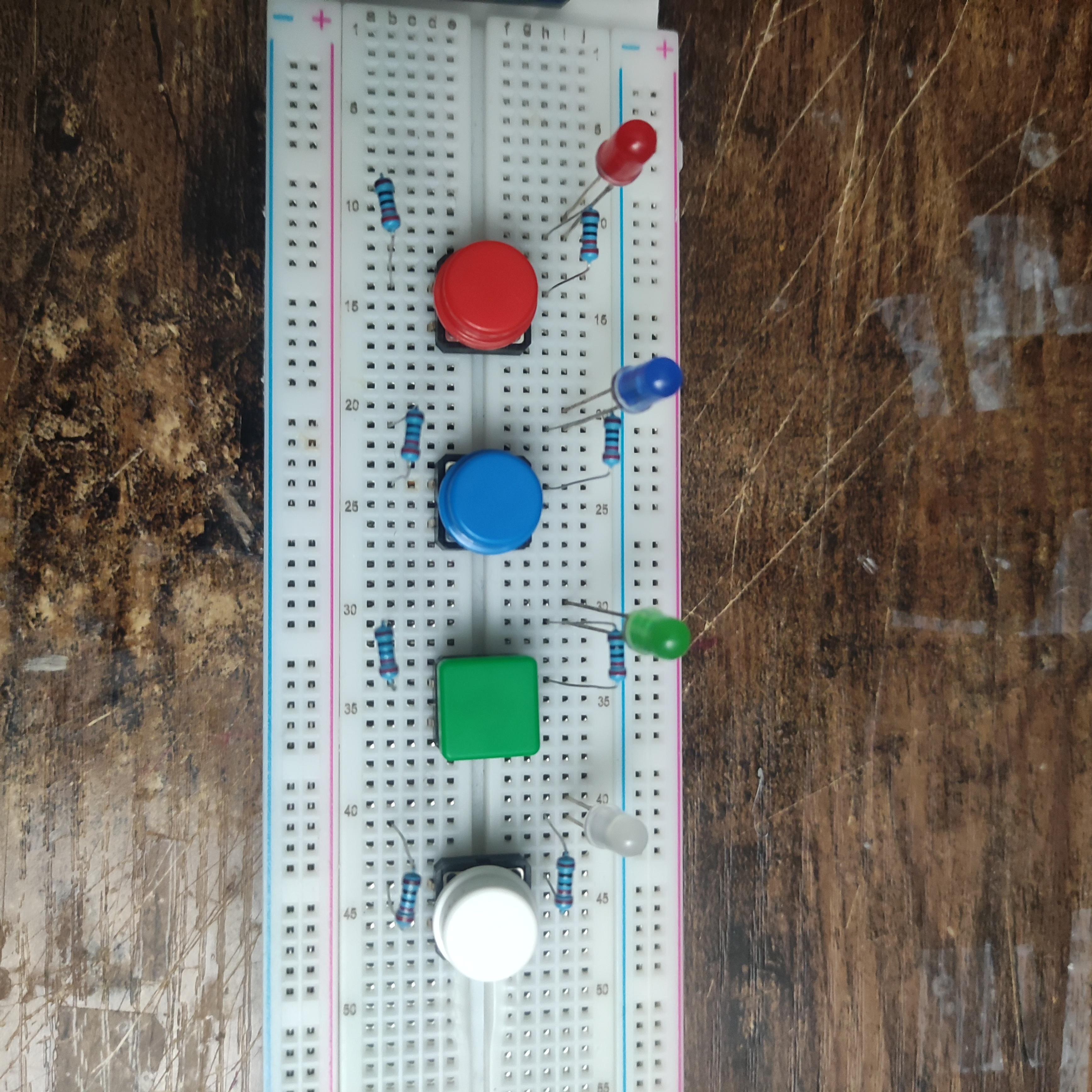
Voltage Wire and Digital Pins
We will need to supply electricity to the LEDs in order to allow them to flash when needed, so we need a voltage wire. Additionally, we must define each of the LED-Button links in our program through digital pins, so we need wires for that as well.
- Take 1 Male-Male Jumper wire and plug one end into the 3.3V slot and place the other end in one slot of the positive terminal (labeled + and contains a red line).
- Take 4 Male-Male Jumper cables and plug each of them into one of the digital pin slots (for simplicity, I used the digital pins 1, 2, 3 and 4)
- Put the other end of the 4 Male-Male Jumper cables in between the right end of the resistor an the left socket of the button, which will make assign the digital pin to that particular slot.
Copper Wiring on Breadboard
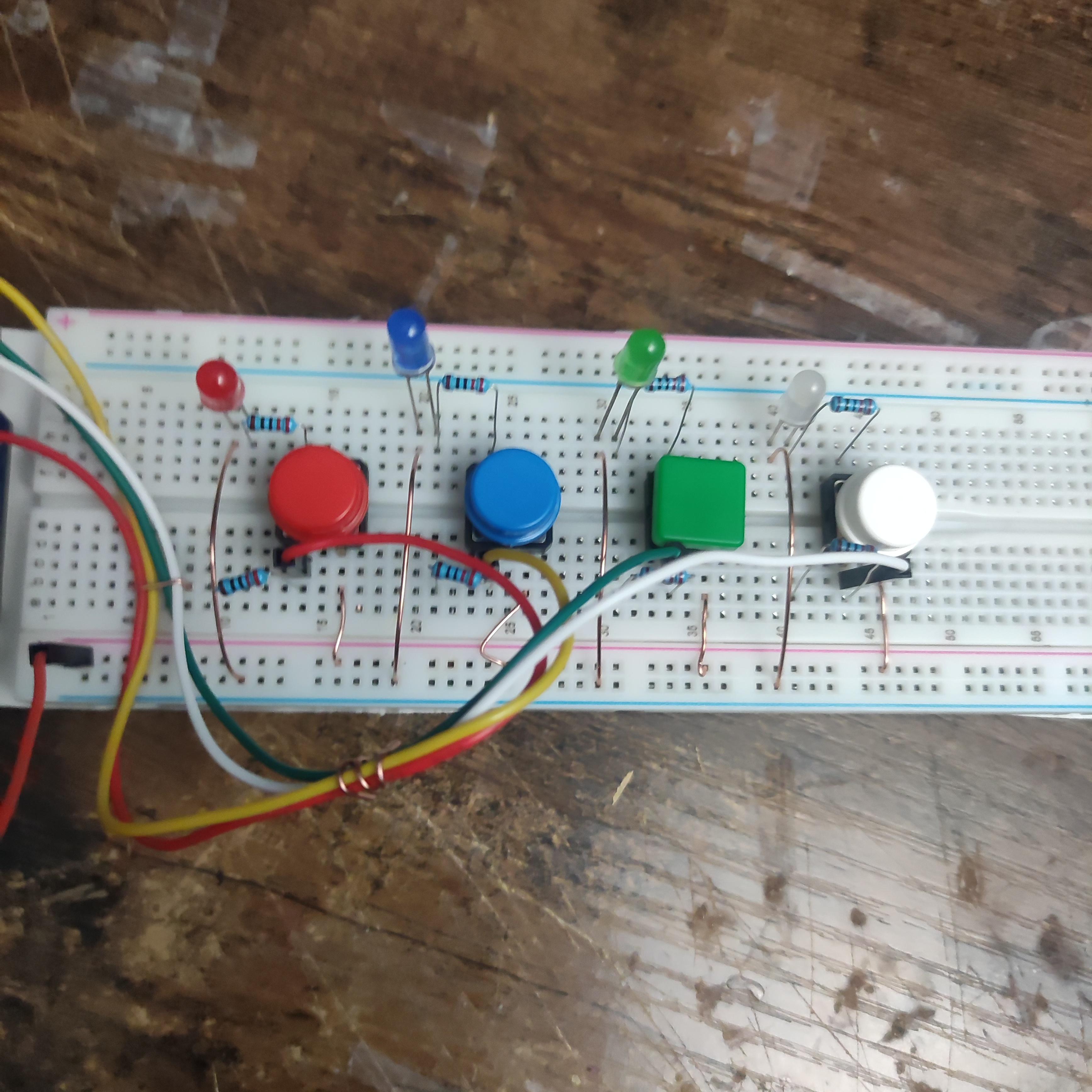
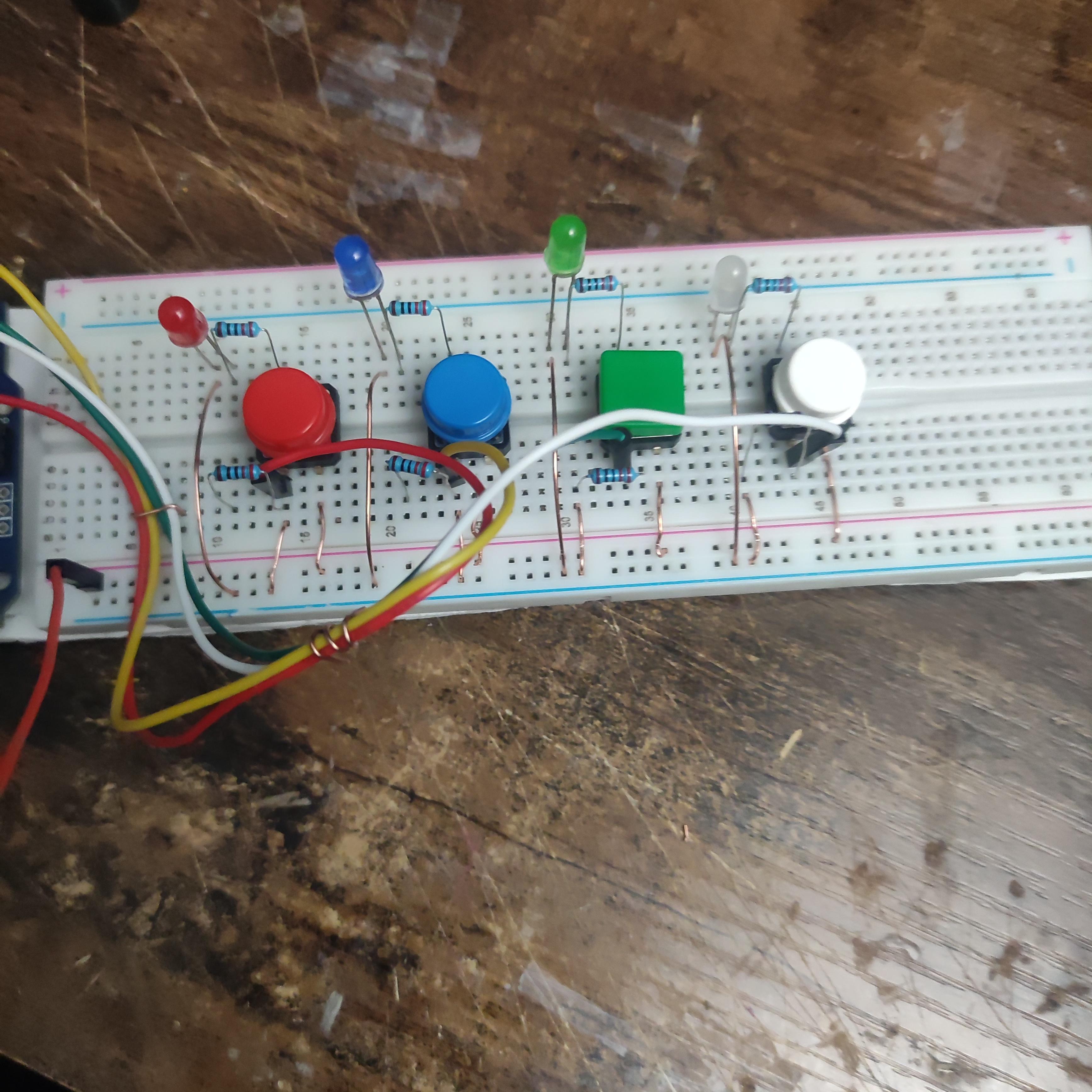
- Cut 4 short copper wire lengths out, around 2 inches, and plug one end right below the negative (-) left terminal on the LED and the negative terminal (-) on the bottom
- Cut out 4 shorter copper wire lengths, around 1 inch, and plug one end in-line with the right side of the button connection and the other end into the positive (+) terminal in the bottom
- Cut out 4 shorter copper wire lengths, around 1 inch, and plug one end in-line with the left button slot (with the resistor and digital pin wire) and the other end of the negative terminal on the bottom (+)
This is the most tedious and minute part of assembling this particular device, so make sure you plug the copper wires in precisely and ensure that all that are needed are placed onto the breadboard. Refer to the diagram above
Programming
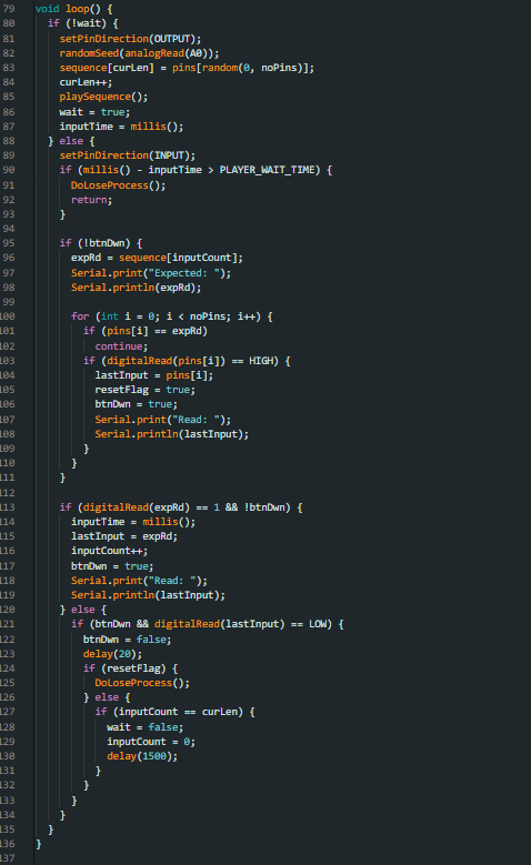
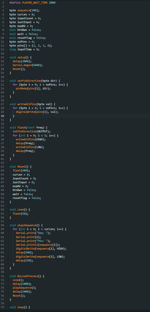
- Define the wait time between button presses as `PLAYER_WAIT_TIME`.
- Declare arrays and variables for the light sequence, input tracking, and pin configurations.
- Create functions to set pin directions and write values to all pins to control LEDs.
- Implement a flashing function to visually indicate game states (win/lose/reset).
- Create a reset function to reset game variables and visually indicate the start of a new game.
- Develop a function to handle the game loss scenario, including a rapid flash and sequence display.
- Implement a function to display the generated light sequence to the player with appropriate delays.
- Set up a loop to handle player input during their turn, checking for correct button presses and timing out if exceeded.
- Integrate game logic to compare player input with the generated sequence, handling correct and incorrect inputs accordingly.
Downloads
3D Print Casing
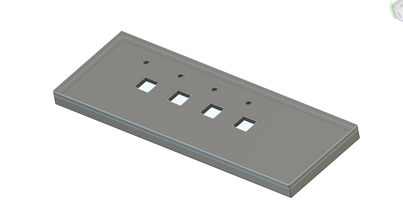
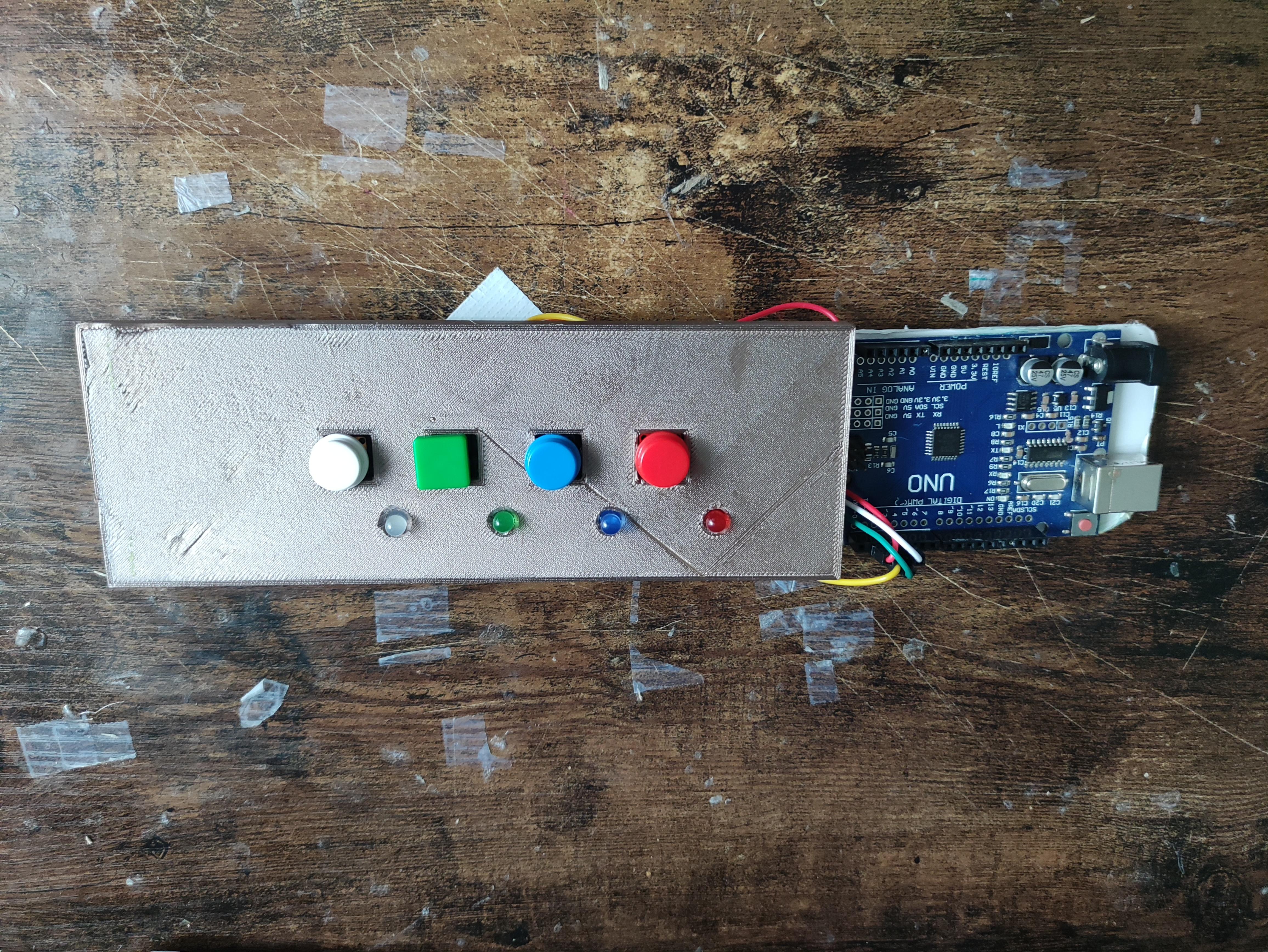
Using Fusion 360, design a breadboard casing for your product leaving cutouts for the buttons and for the LEDs to go through.
For the standard 2.2 inch by 7 inch breadboard with the same spacing that I have mentioned for the LEDs and the Buttons, I have included a f3d file below that I designed for this project that you can import into your slicer.
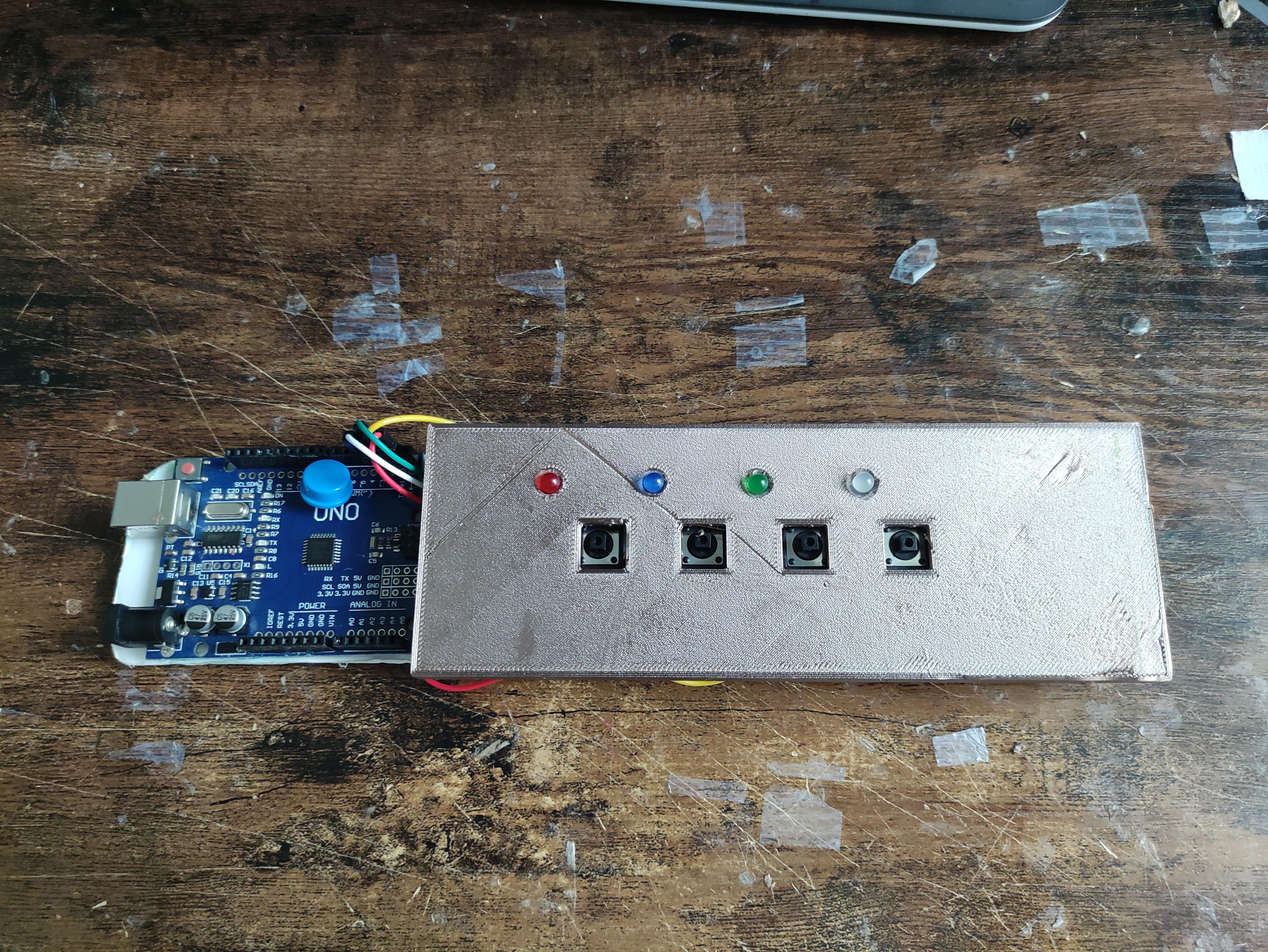
Once you have printed everything, make sure you fold the resistors to not protrude and ensure that the copper wires are not an obstruction. Ensure that everything is still connected as you push the casing on. For my breadboard, this casing was a perfect fit and remained on quite well.
Note: You might have to file the button spaces down a bit if you are using larger button caps as the size I designed takes into account the size of the actual button circuit itself. If you are not using button caps, then you are all set and it should work well. If any issues with fit, you can move the components to see if that solves the issue while ensuring that the components are still connected correctly.
Downloads
Conclusion
Thank you for exploring this Instructable! I hope you found the guide helpful in creating your own memory arcade game using Arduino. Whether you're a novice Arduino enthusiast or a seasoned tinkerer, this project provides an entertaining and educational opportunity to delve into the world of hardware programming. Enjoy building your memory arcade game and have a blast testing your memory! p.s. If you want a challenge, try and beat my personal record of 16 and leave your score in the comments below :)