Arduino 4wd Robot With Ping Sensor "J-Bot"
by JamecoElectronics in Circuits > Arduino
85315 Views, 132 Favorites, 0 Comments
Arduino 4wd Robot With Ping Sensor "J-Bot"
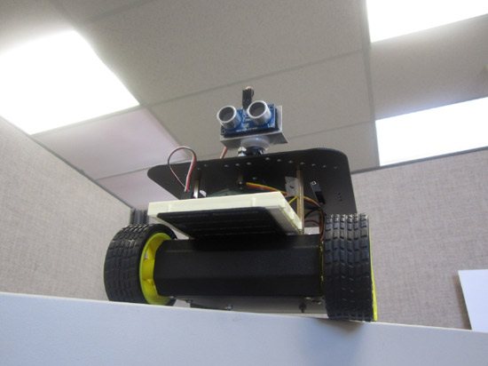
Experience Level: Intermediate (requires soldering)
Time Required: 3-5 hours depending on experience
J-BOT Kit Jameco
Someone mentioned that Jameco needed a robotic mascot. I have always been a tinkerer, especially with radio-controlled electronics and so I volunteered for the chance to design and create the J-Bot. While this was my first autonomous robot build, I'm confident it won't be my last. We thought this would be a fun project to build.
Required tools and parts:
Jameco J-BOT Kit
Arduino UNO
11 AA batteries (5 for the motors and 6 for the Arduino, servo and sensor)
Philips screwdriver
Long nose Pliers
Soldering iron
Solder wire
Helping hands
Building the 4 Wheel Drive Platform
Before building the brains, we'll need the basic platform. I found some good videos to help step me through the process of putting together the same 4 wheel drive platform that is included in the J-Bot kit.
http://www.youtube.com/embed/H_OThKDM44Q
http://www.youtube.com/embed/VkH04Suz87E
http://www.youtube.com/embed/ZXk752IvctI
http://www.youtube.com/embed/IU9lQ-wKoXo
After soldering the wires to the motors, I suggest adding a drop of hot glue to the copper clips so the clips do not rip off because they are very fragile.
http://www.youtube.com/embed/2KnmKhGdK-U
At this point it would be a good idea to label all the cables so you can identify them later. I decided to label them by using regular scotch tape. I labeled the two front motors "FL" and "FR" for front-left and front-right, as well as the back as "BR" and "BL" for back-right and back-left.
Step 2 - Wiring and Mounting Arduino to Platform
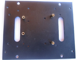
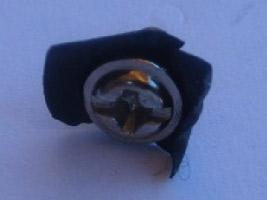
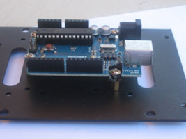
http://www.youtube.com/embed/P4xuYb412G4 This video shows how to wire a battery back.
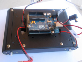
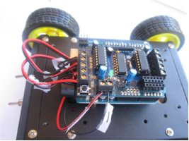
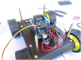
To mount the Arduino to the platform, I first put the standoffs on the Arduino to see where I could mount it. I decided to mount the Arduino on the bottom plate because it would require less drilling. I drilled one hole on the platfom so I could get all four standoffs connected to the platform.
Pull all the wires out from beneath the platform. There should be five cables, four for the motors and one positive battery cable from the switch and the negative cable from the battery pack.
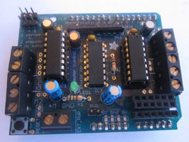
Next we will build the Adafruit motor control shield to control the motors on the platform. This website walks you through the simple build. http://ladyada.net/make/mshield/solder.html
The kit includes some headers so you can solder them onto the motor control shield to make it easier to connect the different sensors. The headers that are provided are 8-position. You will need to cut in the middle of the seventh pin so it will fit onto the motorshield. If you decide not to use the headers, you can solder jumper wires to the board. In this build we will be using pin A0, one grd (ground), and one +5V pin.
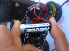
Take both sets of wires from the left side (front left and back left) and test them with an AA battery (not included) to make sure they are wired correctly. Both of the wheels should go the same direction. We are wiring the motors in series. Do the same with the right side.
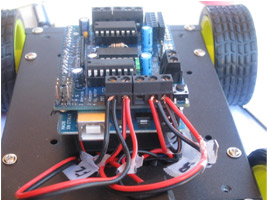
After making sure that the motors are wired correctly, put the left side to the terminal labeled M1. Put the right side to terminal M2.
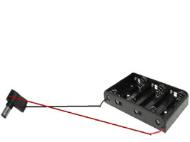
You will need to solder the plug and the battery holder together as shown below. This will provide power to the Arduino UNO
Step 3 - Adding the Breadboard
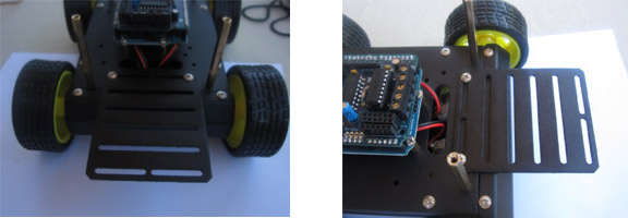
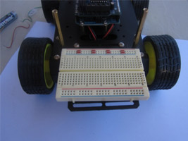
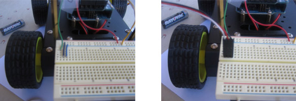
I decided to put the breadboard in the front for easy access; so I put the plate on the front side.
The breadboard comes with double-sided tape. I left the first row of the plate open in case I want to add other sensors later.
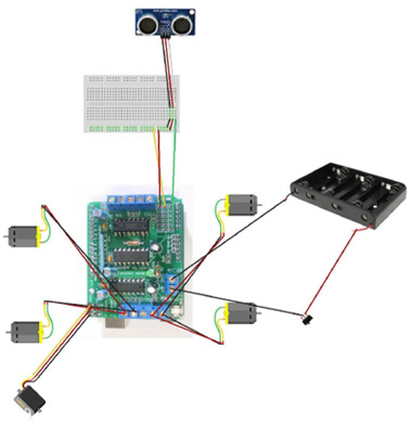
Next, slip the servo cable through the top plate and connect it to SER1.
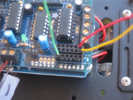
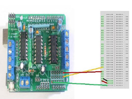
Connect one of the jumpers to pin A0 which is the green cable below. Then connect a jumper cable to ground (yellow) and one to 5 volt (red).
On the breadboard connect the power (red cable) to the first row, the ground (yellow cable) to the second row and the signal cable to the first column.
Put the header into one end of the extension cable, and put it on the board as shown below. The white cable is the signal, the red cable is power and black cable is the ground.
Step 4 - Adding the PING Sensor
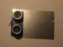
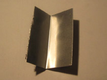
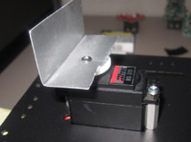
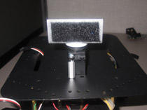
We will use the aluminum piece that came with the breadboard to make a holder for the Ping sensor. Put the sensor on the aluminum piece and mark it with a Sharpie. I used regular scissors to cut the aluminum piece.
Use the edge of a desk or table to fold the aluminum into a 90 degree angle.
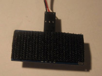
I used a small piece of Velcro to stick the sensor to the mount.
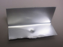
Because the aluminum is thin, I used a regular screwdriver to push in a hole in the middle of the mount.
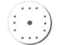
I used the circle horn for the servo and attached the mount to it by using the screw provided.
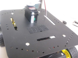
I decided to stick the sensor to the mount with Velcro. The servo was attached to the servo hole on the top of the shield by using the standoffs, two screws and two nuts.
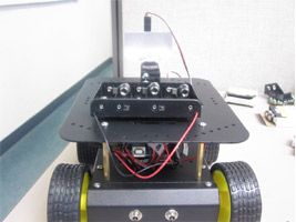
I attached six AA batteries to the top plate with Velcro in case I want to take the top plate off.
Step 5 - Now Time to Program!
This is really the fun part; the sky's the limit when it comes to programming your J-Bot. You can pre-program the route to the candy office machine or coffee pot to have your office buddy make a pick-up. Add a web-cam to peer around high cubicle walls, add speakers to broadcast tunes, add limbs and a remote control to fetch your favorite gadgets. J-Bot is waiting for your imagination to run simply botty.
First you will need to download the Arduino software. Next download the Arduino Stepper/Servo software library and follow the directions on how to put the library in its respective folder.
Next, open the Arduino software and paste the code.
----------------------------------------------------------------------------------------------------------------------------------------------------------------------------------
#include <AFMotor.h> // Enables the Motor library
#include <Servo.h> // Enables the Servo library
Servo PingServo;
AF_DCMotor motor1(1); // Motor 1 is connected to the port 1 on the motor shield
AF_DCMotor motor2(2); // Motor 2 is connected to the port 2 on the motor shield
int minSafeDist = 11 ; // Minimum distance for ping sensor to know when to turn
int pingPin = A0; // Ping sensor is connected to port A0
int centerDist, leftDist, rightDist, backDist; // Define variables center, left, right and back distance
long duration, inches, cm; // Define variables for Ping sensor
void setup() {
PingServo.attach(10); // Servo is attached to pin 10 in the motor shield
PingServo.write(90); // Center the Ping sensor (puts it at 90 degrees)
motor1.setSpeed(215); // Sets the speed of the first motor (At 0, the motors are turned off. 255 is the fastest setting that you are able to use, I used 215 to not push the motors too hard.)
motor2.setSpeed(215); // Sets the speed of the second motor (At 0, the motors are turned off. 255 is the fastest setting that you are able to use, I used 215 to not push the motors too hard.)
Serial.begin(9600); // Enables Serial monitor for debugging purposes
Serial.println("Serial test!"); // Test the Serial communication
}
void AllStop() {
motor1.run(RELEASE); // Turns off motor 1
motor2.run(RELEASE); // Turns off motor 2
}
void AllForward() { // Makes the robot go forward
motor1.run(FORWARD); // Motor 1 goes forward
motor2.run(FORWARD); // Motor 2 goes forward
Serial.println("Going forward"); // Prints a line in the serial monitor
}
void turnRight() { // Makes the robot go right
motor2.run(BACKWARD); // Turns off motor 2
motor1.run(FORWARD); // Motor 1 goes forward
delay(1600); // Time required to turn right (1.6 seconds)
Serial.println("Motors going Right"); // Prints a line in the serial monitor
}
void GoBack(){ // Makes the robot go back
motor2.run(BACKWARD); // Motor 2 goes back
motor1.run(BACKWARD); // Motor 1 goes back
delay(1600); // Time Required to go back (1.6 seconds)
Serial.println("Backward"); // Prints a line in the serial monitor
}
void turnLeft() { // Makes the robot go Left
motor2.run(FORWARD); // Motor 2 goes forward
motor1.run(BACKWARD); // turns off motor 1
delay(1600); //Time Required to turn left (1.6)Seconds
Serial.println("Motors going Left");// Prints a line in the serial monitor
}
// Starts the loop to decide what to do
void loop()
{
LookAhead();
Serial.print(inches);
Serial.println(" inches"); // Prints a line in the serial monitor
if(inches >= minSafeDist) /* If the inches in front of an object is greater than or equal to the minimum safe distance (11 inches), react*/
{
AllForward(); // All wheels forward
delay(110); // Wait 0.11 seconds
}else // If not:
{
AllStop(); // Stop all motors
LookAround(); // Check your surroundings for best route
if(rightDist > leftDist) // If the right distance is greater than the left distance , turn right
{
turnRight();
}else if (leftDist > rightDist) // If the left distance is greater than the right distance , turn left
{
turnLeft();
}else if (leftDist&&rightDist<minSafeDist) // If the left and right distance is smaller than the min safe distance (11 inch) go back
{
GoBack();
}
}
}
unsigned long ping() {
pinMode(pingPin, OUTPUT); // Make the Pingpin to output
digitalWrite(pingPin, LOW); //Send a low pulse
delayMicroseconds(2); // wait for two microseconds
digitalWrite(pingPin, HIGH); // Send a high pulse
delayMicroseconds(5); // wait for 5 micro seconds
digitalWrite(pingPin, LOW); // send a low pulse
pinMode(pingPin,INPUT); // switch the Pingpin to input
duration = pulseIn(pingPin, HIGH); //listen for echo
/*Convert micro seconds to Inches
-------------------------------------*/
inches = microsecondsToInches(duration);
cm = microsecondsToCentimeters(duration);
}
long microsecondsToInches(long microseconds) // converts time to a distance
{
return microseconds / 74 / 2;
}
long microsecondsToCentimeters(long microseconds) // converts time to a distance
{
return microseconds / 29 / 2;
}
void LookAhead() {
PingServo.write(90);// angle to look forward
delay(175); // wait 0.175 seconds
ping();
}
void LookAround(){
PingServo.write(180); // 180° angle
delay(320); // wait 0.32 seconds
ping();
rightDist = inches; //get the right distance
PingServo.write(0); // look to the other side
delay(620); // wait 0.62 seconds
ping();
leftDist = inches; // get the left distance
PingServo.write(90); // 90° angle
delay(275); // wait 0.275 seconds
// Prints a line in the serial monitor
Serial.print("RightDist: ");
Serial.println(rightDist);
Serial.print("LeftDist: ");
Serial.println(leftDist);
Serial.print("CenterDist: ");
Serial.println(centerDist);
}
-------------------------------------------------------------------------------------------------------------------------------------------------------------------------------------
Troubleshooting Guide:
The code will not compile.
1. Make sure the Adafruit motor control library is in its proper folder.
2. Check the code and make sure you copied the complete program.
The IC chips on the Adafruit shield heat up.
1. Check the soldering job. Make sure your soldering is correct on the motor shield.
2. Put a heat sink (P/N 2077335) on the IC. You will need thermal paste (P/N 615312) to put the heat sinks on the IC.
The wheels fall off.
1. Apply a small amount of hot glue to the wheels.