Application of LoRa WSN in Landslide Monitoring Systems
by make2explore in Circuits > Arduino
2570 Views, 11 Favorites, 0 Comments
Application of LoRa WSN in Landslide Monitoring Systems

DIY project using Wio-E5 LoRa Dev Boards for testing use of LoRa WSN in Landslide Monitoring/Detection Systems
Landslide is a critical natural geological hazard that causes severe damage to property, infrastructure, and humans. Historical landslides occurred around the world caused disasters, deaths of number of peoples and destroyed homes, structures and loss of plant life.

What is a landslide and what causes one?
Landslide which is also called as landslip is defined as the movement of mass of rock, debris, or, earth, down a slope. Landslides are a type of "mass wasting," which denotes any down-slope movement of soil and rock under the direct influence of gravity.

Here, Gravity is the primary driving force for a landslide to occur, but there are other factors affecting slope stability, that produce specific conditions that make a slope prone to failure. In many cases, the landslide is triggered by a specific event, (such as, a heavy rainfall, an earthquake, a slope cut to build a road, and many others), although this is not always identifiable.
Hazards can be mitigated mainly through precautionary means, for instance, by restricting or even removing populations from areas with a history of landslides, by restricting certain types of land use, where slope stability is in question, and by installing early warning systems based on the monitoring of ground conditions, such as, strain in rocks and soils, slope displacement, and groundwater levels.
So there are several landslide monitoring Techniques researched in last decades. But they are broadly categorized into three major classes.
- Statistical methods and rating scheme - These are completely analytical methods, Where numerical weights are assigned to each of the triggering parameters of the landslide. All the ratings are sum up to get an aggregated value used to determine a landslide’s likelihood. The higher the value obtained, the higher would be the probability of landslide. This method can develop “Landslide Hazard Mappings” to identify the potential landslide hazards in the area.
- Remote sensing - It is the acquisition of information about an object or phenomenon without making physical contact with the object. This method does not consider intrinsic parameters. Techniques used in this category are, SAR, LISA, LIDAR, GPS, Photogrammetric Technique etc.
- Ground-based systems - In this system, the sensing devices directly contact the terrain, acquiring real-time data. Means, they are Intrinsic, actual in contact with ground and Terrain. Techniques used in this category are, Antenna Based, OTDR, WSN etc.
We are going to make our DIY Project for one of the Ground-based systems Technique, Which is WSN, means Wireless Sensor Networks. We are going to use LoRa Wireless Technology in this WSN system for improving its wireless connectivity during Landslide Monitoring.

Please note that, project which we are going to design is not about high quality or innovative detection or sensing. We are going to cover only communication part. Means, how LoRa WSN can be helpful in reliably, effectively and efficiently conveying, monitored data, to the distant concerned authorities.
Landslide prediction, Early Detection and Evacuation
Although satellite based remote sensing results and Findings are significant, but they also should be backed up by actual ground based monitoring systems for more accurate results. Here, in such cases, the LoRa based WSN can play important role in wireless communication part.
- By monitoring descending velocity of mass in Landslide or subsidence, over period of time, and by using statistical analytical Techniques of likelihood findings, we can predict or early detect the landslide events.
- Here in following table, there are different types of Landslide events are categorized according to the descending velocity of mass or debris.

- So as per these stats, in point of view of safe evacuation of peoples living in Landslide prone areas, these four landslide events can be easily early detected and loss of lives can be avoided. Extremely slow, Very slow, slow, and, moderate movements Landslides can be early detected, before they enter into rapid and extremely rapid modes.
Potential Scenarios of project’s application
Lets see the feasible scenarios of project’s application. We will consider three main cases.
- First, Landslides occurring at Remote villages near mountains,
- Cities or towns near mountains, and
- Roads or Highways passing through hilly regions.

- If we consider this city's case, then use of LoRa WSN, or LoRaWAN will be unnecessary here, because, other more faster and reliable Wired or wireless communication services like, Ethernet, GSM 5G, Wi-Fi, will be available near this town.
- But for other two scenarios, There may be lack or unavailability of Cellular or Wi-Fi Networks. In such areas, to monitor data of the Landslide events, LoRa wireless sensor networks, can play very important role. If these sites comes in range of 5 to 10 Kilometers, from well connected city, then P2P LoRa or LoRaWAN can be used. Moreover P2P, means, Point to point/ (Peer-to-Peer) LoRa network, will be more affordable than that of LoRaWAN.
- **Since our area has very poor connectivity of LoRaWAN Gateways, we will consider third scenario for implementation of our project as more sophisticated than other two. Lets see this third scenario in detail.

- Most of the time, roads passing through mountains lacks wireless connectivity. Landslides occurring in such areas may cause accidents and closure of the roads. If any Landslide monitoring system deployed in such areas, it is very difficult to send its data to concerned authorities if cellular networks have no coverage. That’s why we are proposing solution with LoRa WSN. Since LoRa can easily cover distance up to 5-10 Kilometers.
- So, for the implementation of this Project's concept we'll need LoRa Transceiver modules or development boards with good LoRa transmission range.
We'd like to extend our sincere gratitude to Seeed Studio for providing us their excellent hardware's (Wio-E5 Series LoRa Development Kits) for prototype implementation of this Project.
Supplies
Required Components -
- Seeed Studio Wio Terminal
- Seeed Studio Grove - Wio-E5 (STM32WLE5JC)
- Seeed Studio Wio-E5 LoRa Dev Kit
- Seeed Studio Wio-E5 Mini Dev Board
- Arduino Mega 2560
- NodeMCU ESP8266
- ADXL345 Accelerometer
- Capacitive Soil Moisture Sensor
- Resistive Soil Moisture Sensor
- Vibration Sensor
- Tipping Bucket Rain Gauge - 10K Pot
- DHT22 temperature-humidity sensor
- 1.3"IPS Display (240x240P)
- 1.8"TFT Display
- 0.96" OLED Display
- MB102 Breadboard Power converter module
- Logic Level Shifter Module
Wio-E5 LoRa Development Boards
![[Device Overview] Seeed Studio's Wio-E5 LoRa Development Boards](/proxy/?url=https://content.instructables.com/FP9/05RQ/LGTF9GIN/FP905RQLGTF9GIN.jpg&filename=[Device Overview] Seeed Studio's Wio-E5 LoRa Development Boards)
Check out our detailed review video, in which we have explicated detailed review of these amazing LoRa Development boards. Wio-E5 Dev kit and Wio-E5 Mini. Manufactured by the Seeed Studio. We have seen its unboxing, Features, specifications, Datasheets, AT commands configuration guide, and, We have also seen demo of serial configuration of these boards via AT commands.
Project Implementation
Now lets see how Wio-E5 Lora modules will be used in this project.
- Suppose there is Landslide monitoring system, which incorporated different LoRa wireless sensor nodes.

- Suppose this system has been deployed at Landslide prone area in hilly road. Where WiFi and cellular networks are unavailable. This system is connected to nearby cities and Highway Patrol Authorities, via LoRa.
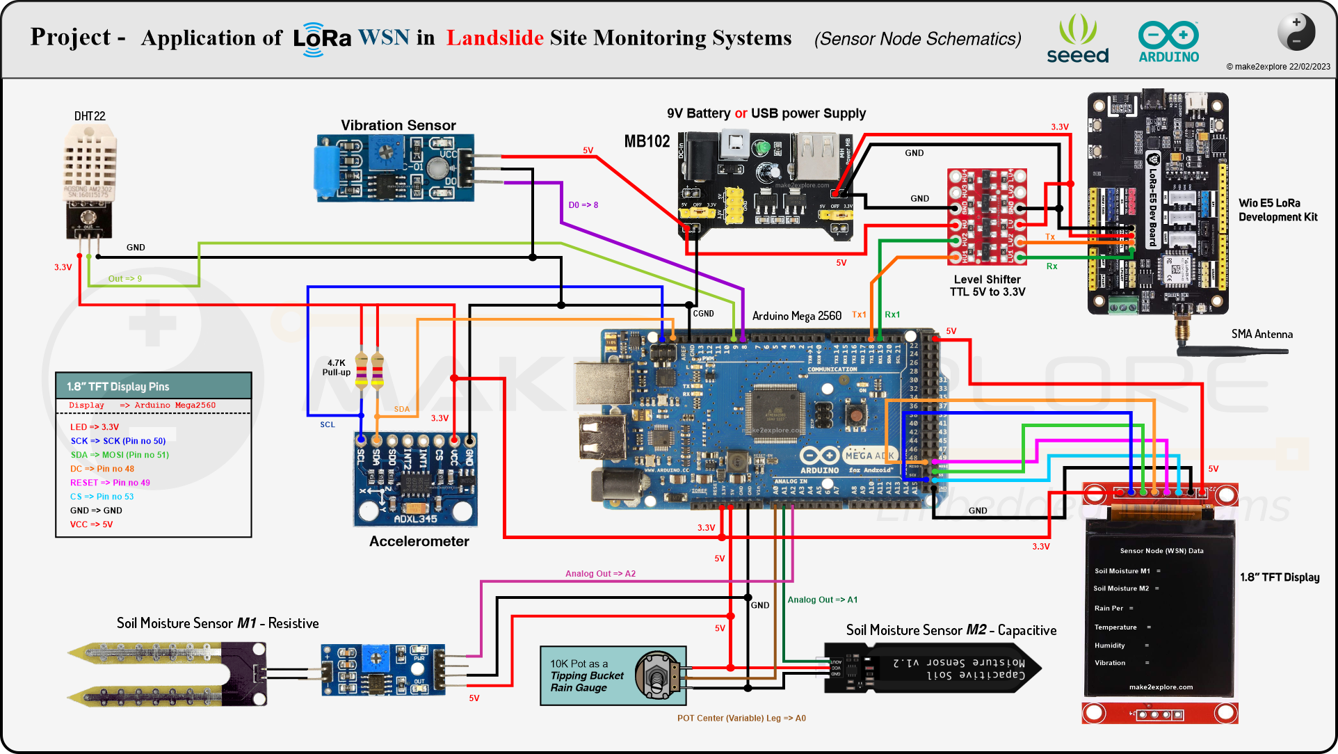
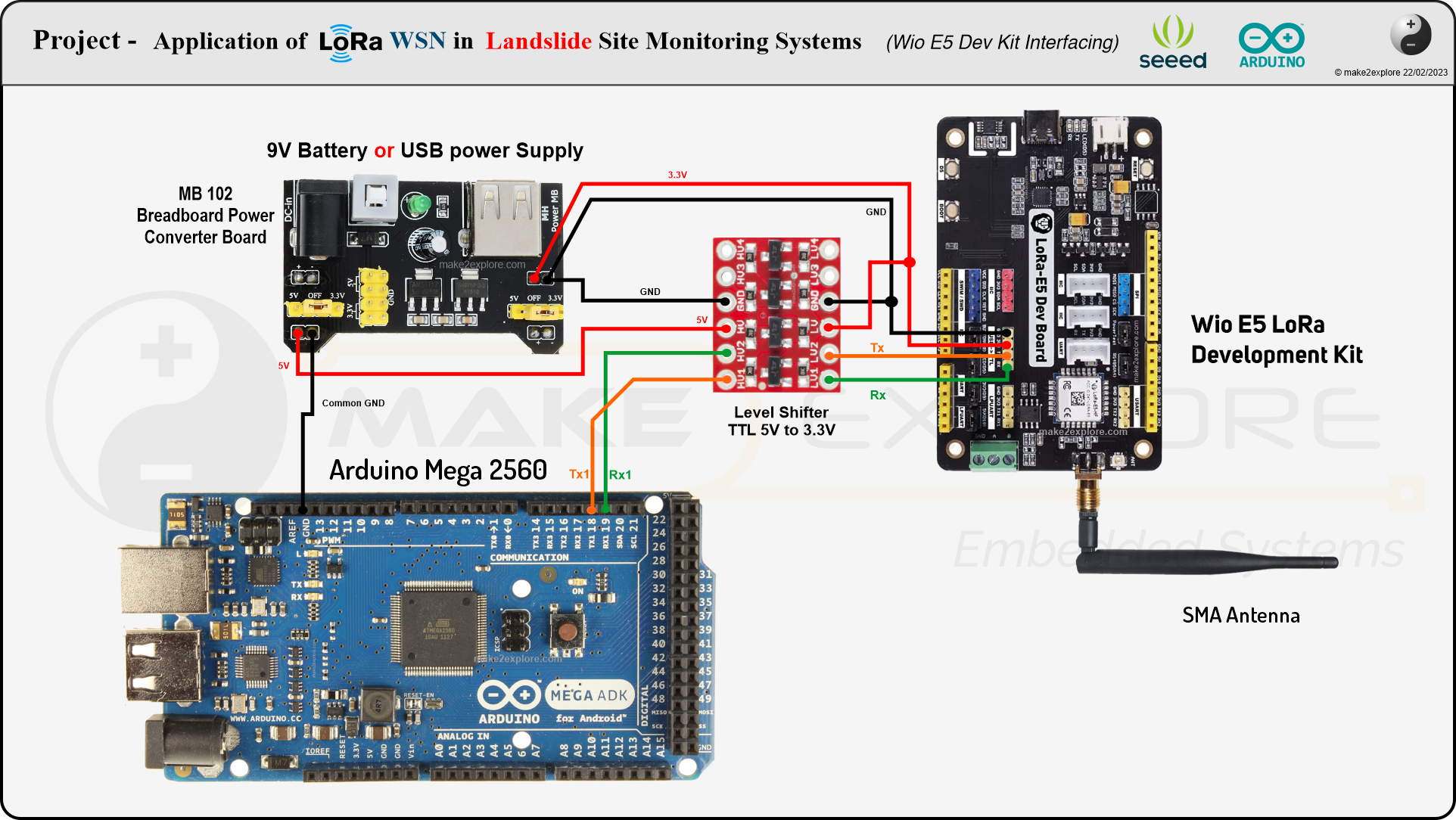
- For That, We will use Wio-E5 Dev Kit as Sensor Node. In actual Landslide monitoring system there will be multiple sensor nodes for covering whole Downslope area, but for the sake of design simplicity, we will simulate only 7 sensor nodes using Wio-E5 Dev kit and Arduino Mega2560.
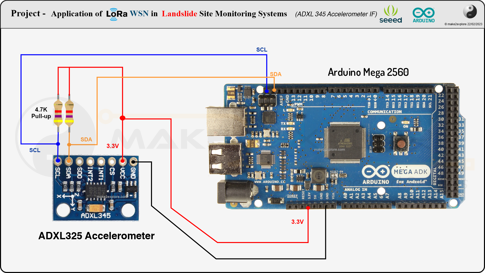
- Which includes two soil moisture sensors, One MEMS Accelerometer, "Tipping bucket Rain Gauge Sensor", Vibration Sensor, Temperature and Humidity Sensor.
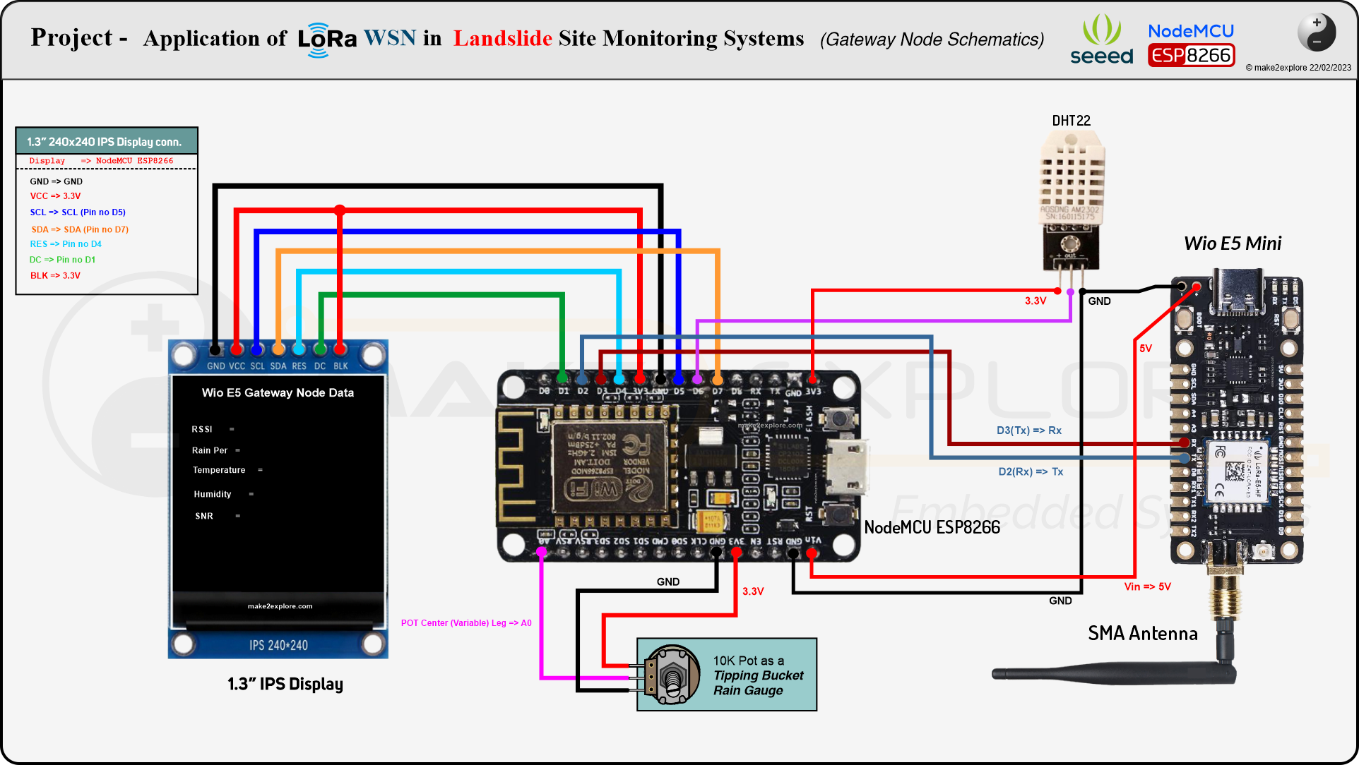
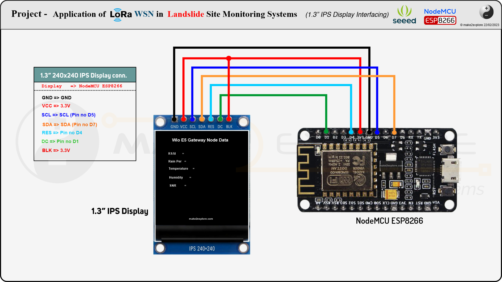
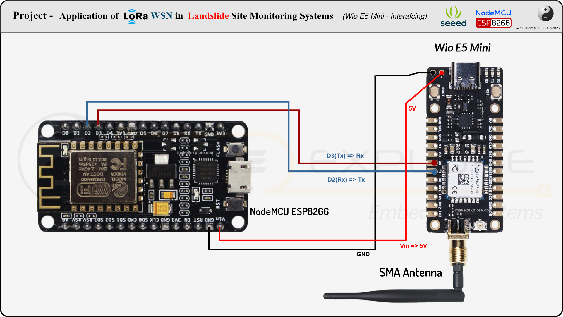
- As shown in above figure, all these LoRa sensor nodes will be then connected to Gateway Node. At Gateway node, we will use another LoRa development board by Seeed studio, that is Wio-E5 Mini, interfaced with, NodeMCU ESP8266.
- As figure shows, the Gateway node will be at some distance from other wireless sensor nodes at Landslide prone area. This gateway node also include some sensor, like, another "tipping bucket Rain Gauge Sensor" and Temperature Humidity sensor.
- This is just for conveying 'rain density difference' in landslide prone areas and other surrounding areas. Gateway device will receive WSN data from different sensor nodes from landslide prone area. Then, it will add data from its own area, then finally combining both place's data together in one frame it will send it to the end nodes.
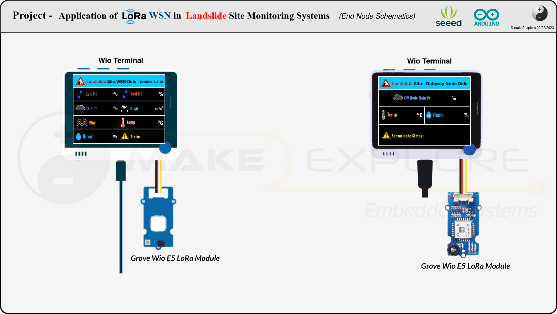
- We will use Wio Terminal interfaced with Grove Wio-E5 module as an End Device. It will receive data relayed by Gateway device. Now once we receive all the sensor data from the Landslide prone places, at well connected cities, we can do anything with it. Like, cloud sharing, processing, analysis, prediction and Early detection.
- Therefore, by monitoring descending velocity of mass in Landslides or subsidence over period of time, and by using statistical analytical Techniques of likelihood findings, we can predict, or, early detect the landslide events. And Eventually, Concerned Authorities can take Evacuation and safety measures as per the findings.
Functional Block Diagram for Each Node
Ok so following figure shows the functional block diagram for each node, including its components.

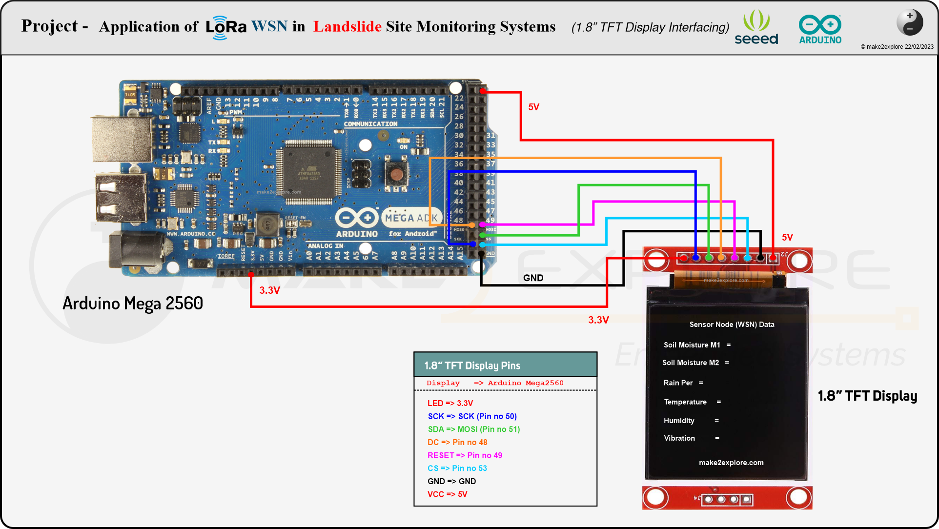
Below in schematics section, We have shared all the circuit schematics of the Project, for Sender Node, Gateway Node and for End node. We will also share the other circuit diagrams for each individual interfacing of components. We highly recommend you, to go stepwise. Test all devices with separate interfacings and then combine them all to make final project. We will share all circuit schematics on Project's GitHub page.
Circuit Diagrams
There are three circuits/nodes in our project. Sensor Node, Gateway Node and End Node. So, there are 3 circuits
We will also share the other circuit diagrams for each individual interfacing of components. We highly recommend you, to go stepwise. Test all devices with separate interfacings and then combine them all to make final project. We will share all circuit schematics on Project's GitHub page.
Software and Programs
Since the Wio-E5 LoRa Dev boards and Grove Module consist of this Wio-E5 LoRaWAN chip with an MCU, there are three main ways to utilize the Wio-E5 Dev Board:
- Connect Wio-E5 Dev Board to PC via USB and control by AT commands - There is a built-in USB to UART function on board, you could just simply connect the Wio-E5 Dev Board to your PC with a USB type C cable, and use serial communication software to send AT commands and read data from the board.
- Connect Wio-E5 Dev Board to another mainboard via UART and control by AT commands - For example, connect Wio-E5 Dev Board to Arduino Uno Board via UART, and send AT commands and read data from Uno through Arduino IDE serial monitor.
- Develop user application by using SDK - Develop your own LoRa development board with MCU function by using STM32Cube Programmer, which is the SDK officially provided by STMicroelectronics.
As shown in above block diagram we are going to use second method. We are going to use Arduino Mega2560, NodeMCU ESP8266 and Wio Terminal with Wio-E5 Dev boards and Grove Module in our project.
Seeed studio have extensive and thorough documentation portal, means Wiki encyclopedia, for each of their devices and platforms. You can go to Wiki links of Wio-E5 LoRa Dev boards, you will get plenty of information about how to getting started and program these boards. We have explained all the details in our review video
For testing these Wio-E5 dev kits in P2P mode without LoRaWAN, you can also refer this excellent Hackster tutorial by Sufian Kaki Aslam.
- Wio-E5 series has a built-in AT command firmware, which supports LoRaWAN Class A/B/C protocol and a wide frequency plan: EU868/US915/AU915/AS923/KR920/IN865. With this AT command firmware, developers can easily and quickly build their prototype or application. You can download the 'AT Command Specification Guide' from Wio-E5 Wiki page.
- The main AT command Mode, which we have used in this project is, the TEST command, as the documentation says,
The TEST command is not like other command, it is a serious command, includes several sub-commands, refer to table below. With test mode, user could do RF performance test quickly without any knowledge of LoRa chip. Commands which are related to RF configuration is disabled in test mode.

TEST MODE command - and subcommands
Before starting communication between two LoRa nodes, we need to run specific sequence of commands to configure Wio-E5 Dev boards in LoRa Transmitter and LoRa Receiver Modes. Please go through following two sequences,
TEST Mode AT Command Sequence for Wio-E5 LoRa Boards -
for LoRa Transmitter
===== Wio-E5 LoRa Transmitter ====
AT
AT+MODE=TEST
AT+TEST=RFCFG,866,SF12,125,12,15,14,ON,OFF,OFF
AT+TEST=TXLRPKT, "Hello"
AT+TEST=TXLRSTR, "Hello"
for LoRa Receiver
===== Wio-E5 LoRa Receiver ====
AT
AT+MODE=TEST
AT+TEST=RFCFG,866,SF12,125,12,15,14,ON,OFF,OFF
AT+TEST=RXLRPKT
You'll find out that these are subcommands which are given above in TEST mode.

- Command RFCFG - we have to use this command to set the RF configuration. Here, please note that, you have to set the Lora frequency or band, as per your country and region. As we are testing it in India, we have set it as Standard, IN865 band. likewise, you have to set it as per your countries LoRa Standard allocated by LoRa Alliance.

You can see how we used RFCFG command and TEST command in the following code snippet (From our Projects Source Code), which is the function to configure Wio-E5 Lora Boards in Test mode.

Code Snippet from DIY Project's Source Code - revealing how the AT commands used to configure Wio-E5 Boards
- Then for sending LoRa packets from sender to receiver - we have to use another commands from above give code sequences, which are TXLRPKT and TXLRSTR.

- To receive the LoRa data packets sent by sender at Receiver Node we have to be in reception mode, following command sequence configures Wio-E5 in LoRa receiver Mode

Please note that the Wio-E5 LoRa Boards can receive the messages only in HEX format whereas it can transmit in both HEX as well as STRING format.
There are three circuits/nodes in our project. Sensor Node, Gateway Node and End Node. So, there are 3 circuits and 3 different source codes. We have given the source codes below in attachments section. You can also refer to Projects GitHub repo to refer it.
We have added detailed comments for each section of the program, to easily understand, for what purpose that code snippet is used there. Therefore, you can understand, what's going on with these functions and variables. So, Similarly, for other two interfacing circuits. Which are the Gateway Node, and, End Node. In their respective code implementations. We have added detailed comments to each important code snippet, functions and subroutines to guide you through these code implementations.
Demo - 1
![[Device Overview] Seeed Studio's Wio-E5 LoRa Development Boards](/proxy/?url=https://content.instructables.com/F4W/MPHB/LGTF9GK2/F4WMPHBLGTF9GK2.jpg&filename=[Device Overview] Seeed Studio's Wio-E5 LoRa Development Boards)
We have made detailed review video of these amazing LoRa development boards, Wio E5 Mini and Wio E5 Lora Dev Kit. Manufactured by the Seeed Studio. In which, We have seen its unboxing, Features, specifications, Datasheets, AT commands configuration guide and We have also seen demo of serial configuration of these boards via AT commands.
Demo - 2
![[DIY Project] Application of Wio-E5 Dev Boards in LoRa WSN](/proxy/?url=https://content.instructables.com/FM9/313X/LG6K4QJX/FM9313XLG6K4QJX.jpg&filename=[DIY Project] Application of Wio-E5 Dev Boards in LoRa WSN)
We have also made detailed video of the DIY Project using these Wio-E5 Development kits. Application of LoRa WSN in Landslide Monitoring Systems. In which we have explained theory, problem statement, different project scenario's, Functional Block diagram, Circuit diagrams and Source code.
Please note that This is just simple DIY prototype for testing application of LoRa WSN in Landslide monitoring systems. In actual/real time Landslide monitoring systems may have completely different setup, different sensors, advanced controllers, and other high quality components, which would have way better resolutions, performance and response time than our prototype.
It is not optimized, designed, or, intended for, deployment in Landslide hazard prone sites, or likelihood areas. Our DIY project is purely for academic and study purpose.
Future Update Ideas
This project was tested in Lab Environment with basic sensor. We're yet to test it in open world. We will test this DIY Project prototype in open area in real time, We will check its transmission range in plain LOS (line of sight).
Documentation
Projects all data, Documents, Source Codes, Libraries, Circuit Schematics will be available on GitHub Repository
https://github.com/make2explore/SEEED-Wio-E5-LoRa-Dev-Boards-Overview
(CC BY-NC-SA 4.0)
Suggestions about Project design, Circuits, source code modifications, Optimization, Errors/Bugs findings and queries are most welcomed.
Credits
Thank you Seeed Studio, for supporting this project with their amazing hardware. Furthermore, we'd like to thanks to all the peoples, websites and entities who helped us (directly/indirectly) in this project.