Apple Magsafe Power Adapter Cable Saver
by anthonylimko in Circuits > Apple
10507 Views, 19 Favorites, 0 Comments
Apple Magsafe Power Adapter Cable Saver
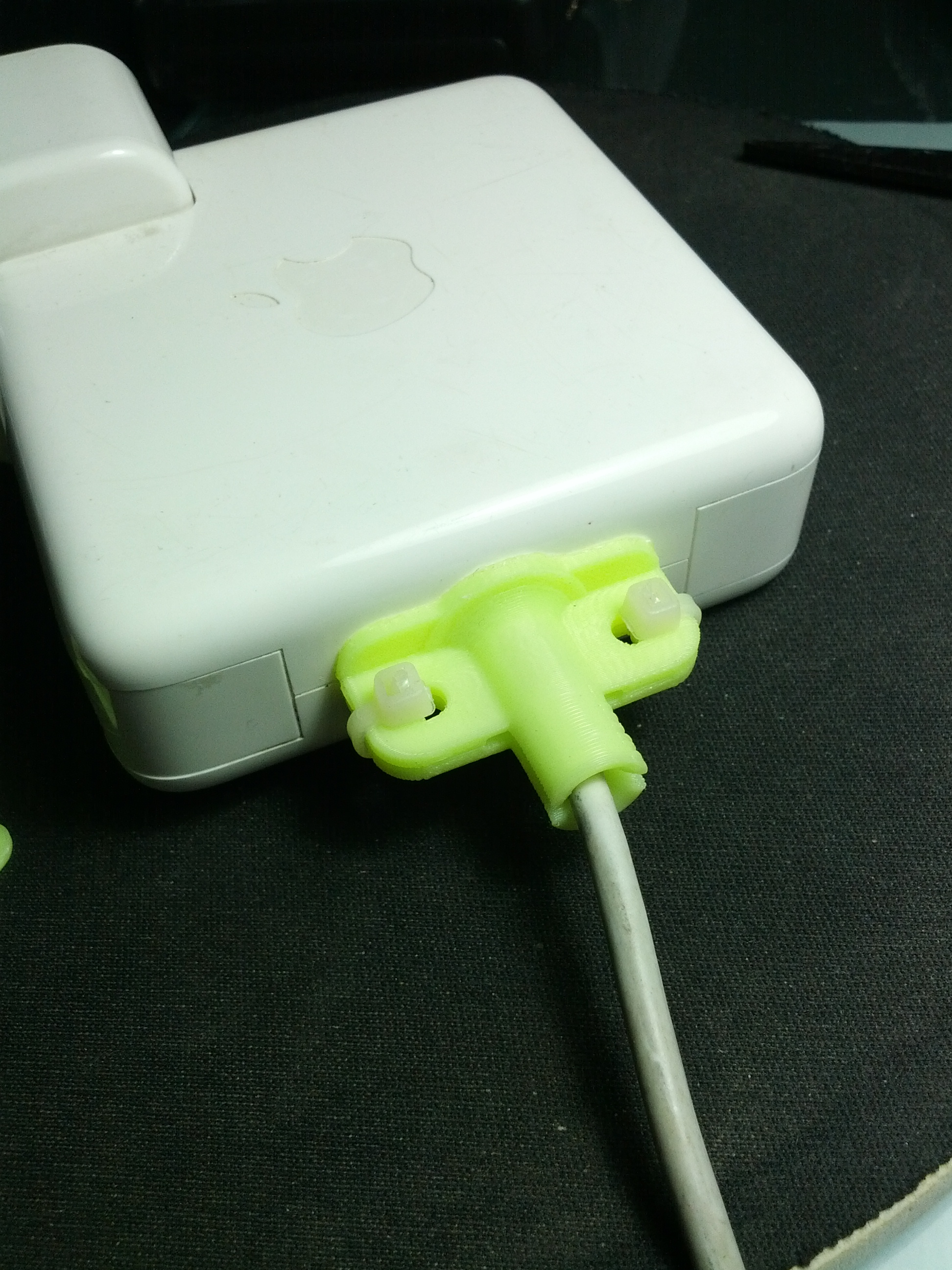
UPDATES! The following video is a continual improvement of my version posted here. It has been called MagSavior - The Apple Magsafe Adapter Saver. The new version is posted in both Thingiverse: http://www.thingiverse.com/thing:154463 and Indiegogo website: http://www.indiegogo.com/projects/magsavior-save-your-magsafe-power-adapter. Please have your support by contributing to our project. Thank you.
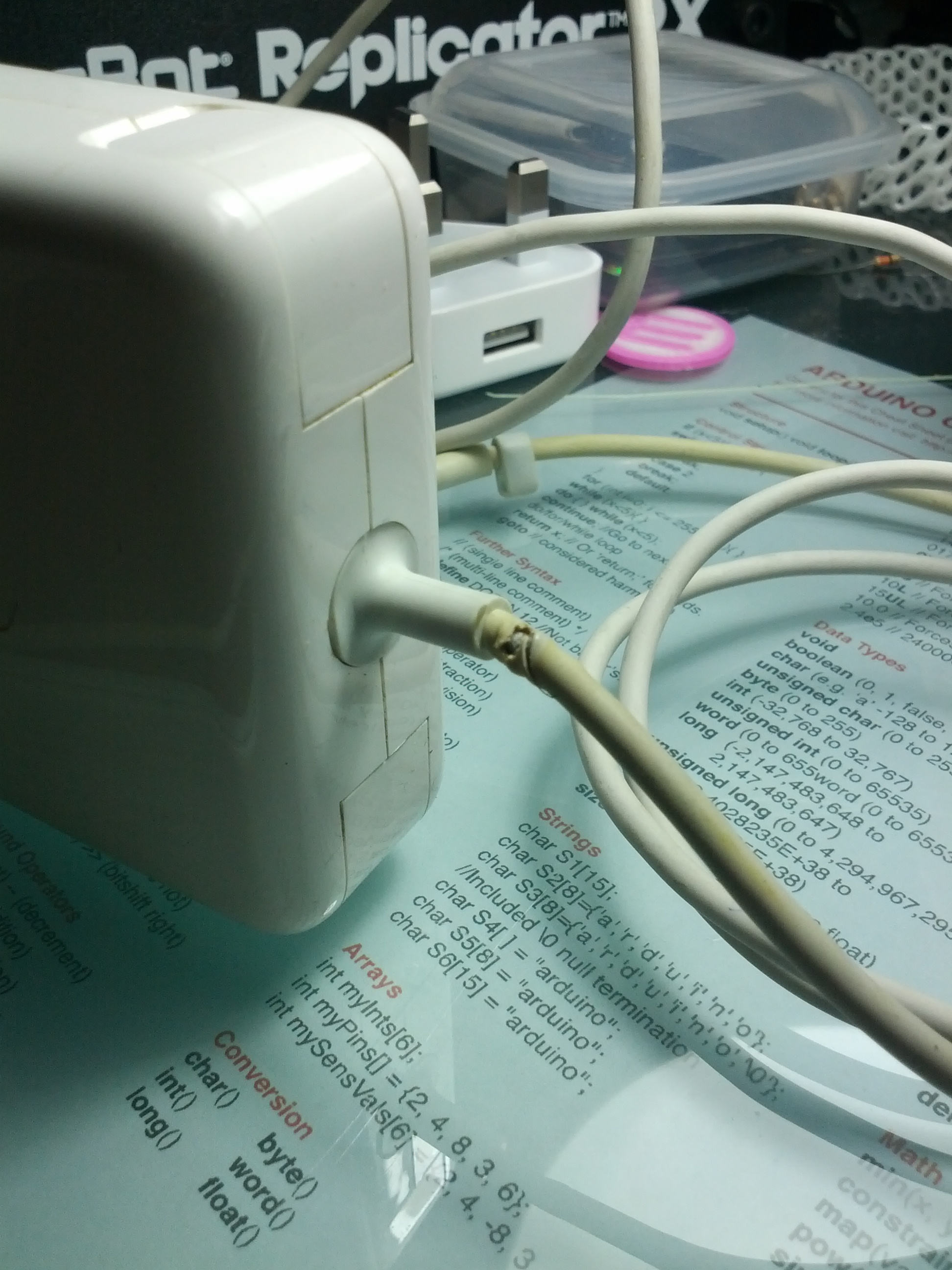
Have you ever encountered your MagSafe power adapter for the MacBook blown away suddenly one day and you have to buy another one? Have you noted that the joining part of the adapter and the cable have a kink in it? That is because the negative shielding has worn off. (See my photo attached!) Thus will create lots of electrical stress onto the adapter and one day you will hear the "POP" sound.
If your MagSafe is still working and wish to prolong the life span before googling "How to fix Magsafe adapter".
I have made this little clip that is able to strengthen the flexible end of the joining part between the cable and the adapter.
I have posted on thingiverse on two types. One original and one remix.
Original Design: http://www.thingiverse.com/thing:137534
Remix: http://www.thingiverse.com/thing:141012
Here is the step by step on constructing the model from 123D Design + Assembly of the complete unit.
Draw the Center Core Profile and Revolve
1. First draw the center core profile as per diagram.
2. Select the profile and use construct ---> revolve tool
3. Revolve 360 deg and new solid as shown in second dia.
4. draw the side flank as shown.
2. Select the profile and use construct ---> revolve tool
3. Revolve 360 deg and new solid as shown in second dia.
4. draw the side flank as shown.
Extrude the Side Flank
Extriude the side flank equally down and up for 2mm thick. Total 4mm thick.
Make sure you select New Solid (By default it is Cut)
Make sure you select New Solid (By default it is Cut)
Downloads
Drawing the Base
1. Draw a rectangle base as according to measure.
2. Extrude 6.5mm on both end. Resulting thckness will be 13mm as shown.
2. Extrude 6.5mm on both end. Resulting thckness will be 13mm as shown.
Cutting the Parting Slot
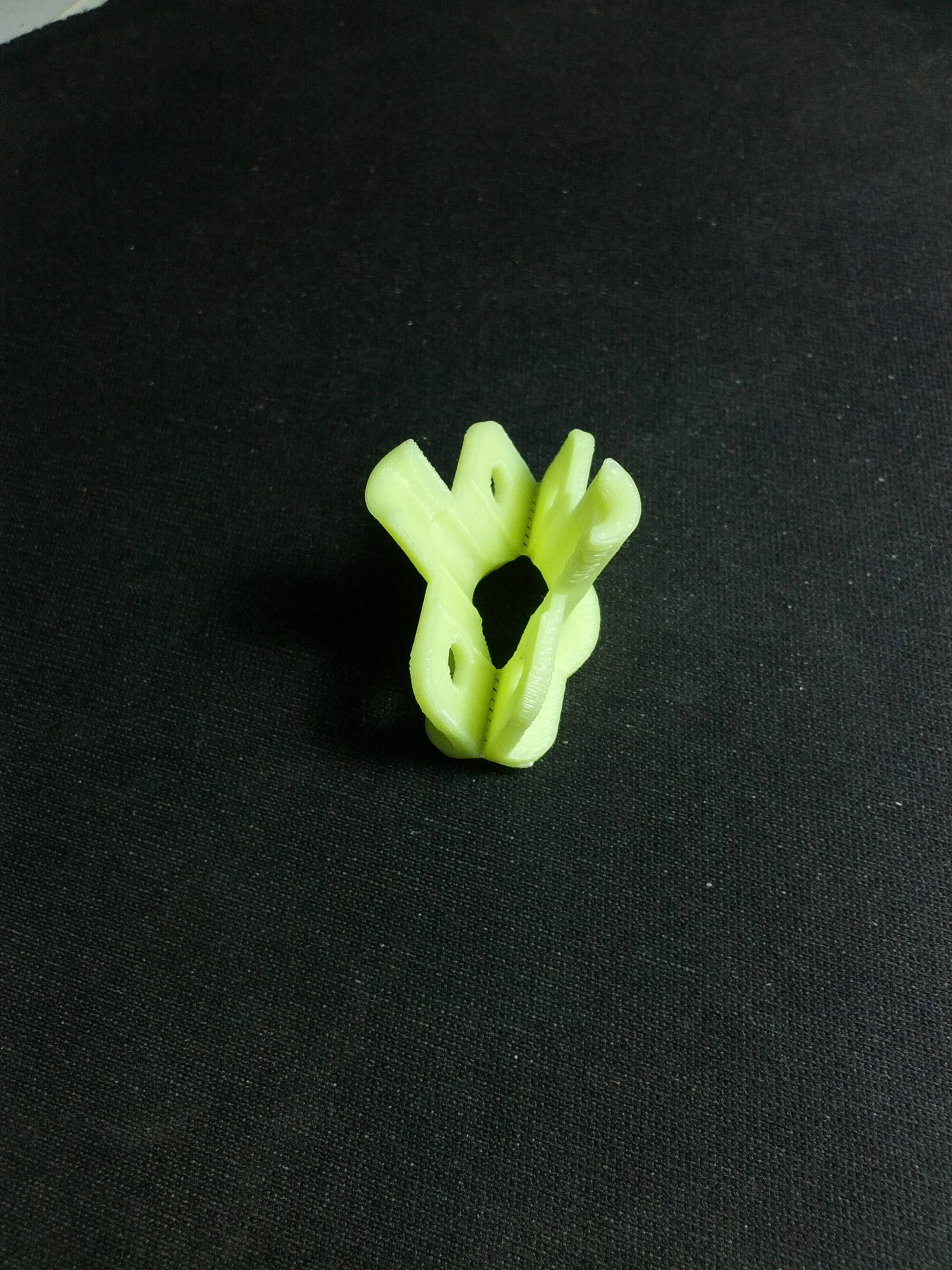
1. Draw the rectangle according the dimension of the picture
2. Raise up the rectangle for 0.2mm. This is to attached a joining for the bottom.
3. Extrude the cut for 0.15mm.
2. Raise up the rectangle for 0.2mm. This is to attached a joining for the bottom.
3. Extrude the cut for 0.15mm.
Center Cut Through Slot
1. Draw rectangle profile as attached.
2. Extrude thickness 1.5mm.
2. Extrude thickness 1.5mm.
Cut a Through Hole Using Revolve Cut Method
1. Draw a off center profile as according to diagram.
2. Do a 360 deg. revolve cut.
Note: You can also cut through via the top.
2. Do a 360 deg. revolve cut.
Note: You can also cut through via the top.
Revolve Cut the Bottom
1. Draw rectangle as according to the diagram.
2. Revolve cut 360 deg.
2. Revolve cut 360 deg.
Extrude Cut Two Holes for Cable Ties
1. Draw two circles measuring 6mm from the top and side flank.
2. Do a extrude cut to the back.
2. Do a extrude cut to the back.
Fillet the Top Internal Hole
1. Select the two top inner arc
2. Fillet 3mm
2. Fillet 3mm
Downloads
Fillet the Flank
1. Select the four corners of the flank.
2. Fillet 4mm.
2. Fillet 4mm.
Downloads
Fillet the Base
Fillet 3mm at the 4 corners of the base.
Downloads
Chamfer the Base
Select the two arc at the center of the hole.
Chamfer 3.5mm
Chamfer 3.5mm
Final Fillet
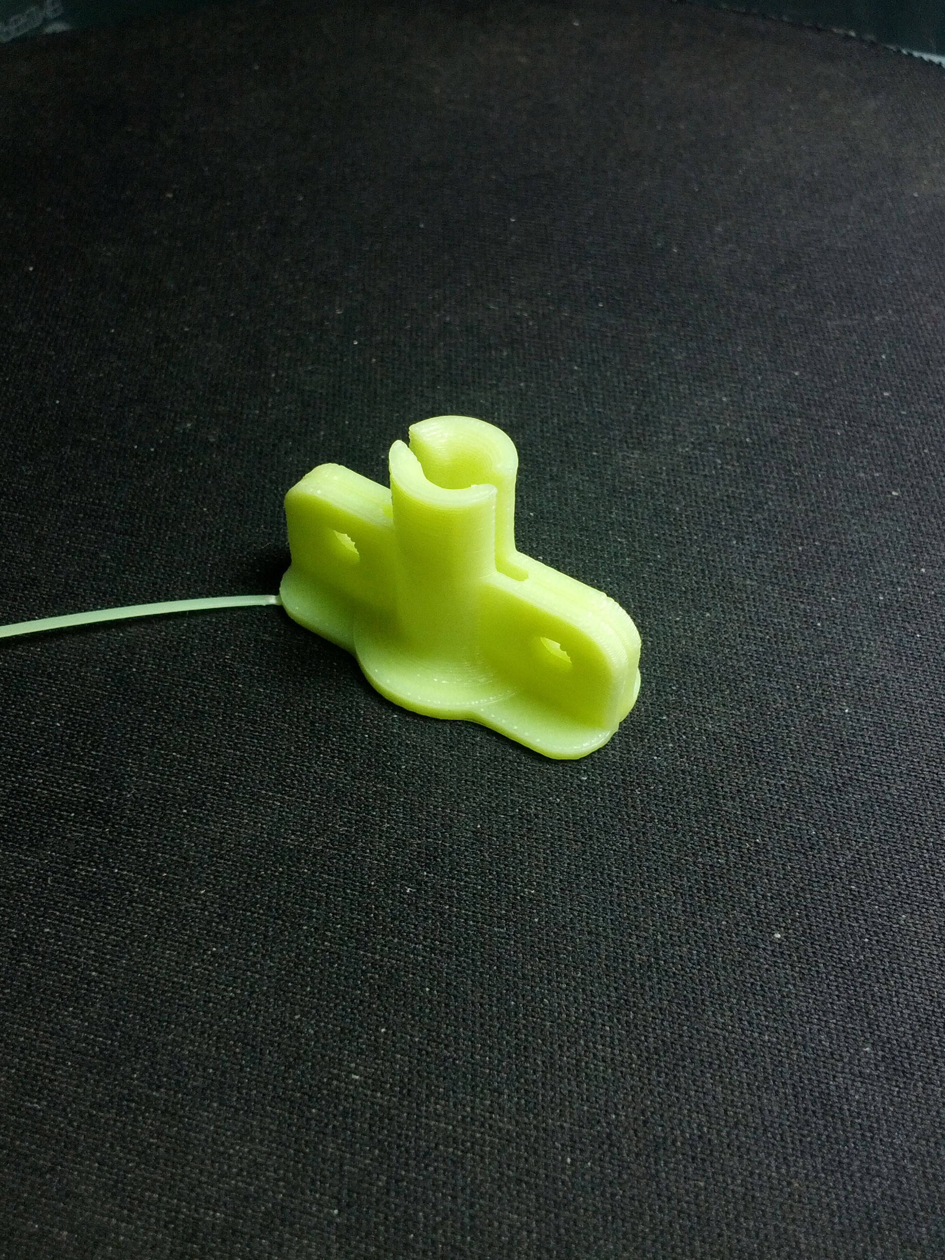
Finally, the fillet at the stem for 3mm.
Downloads
Assembly of the Unit
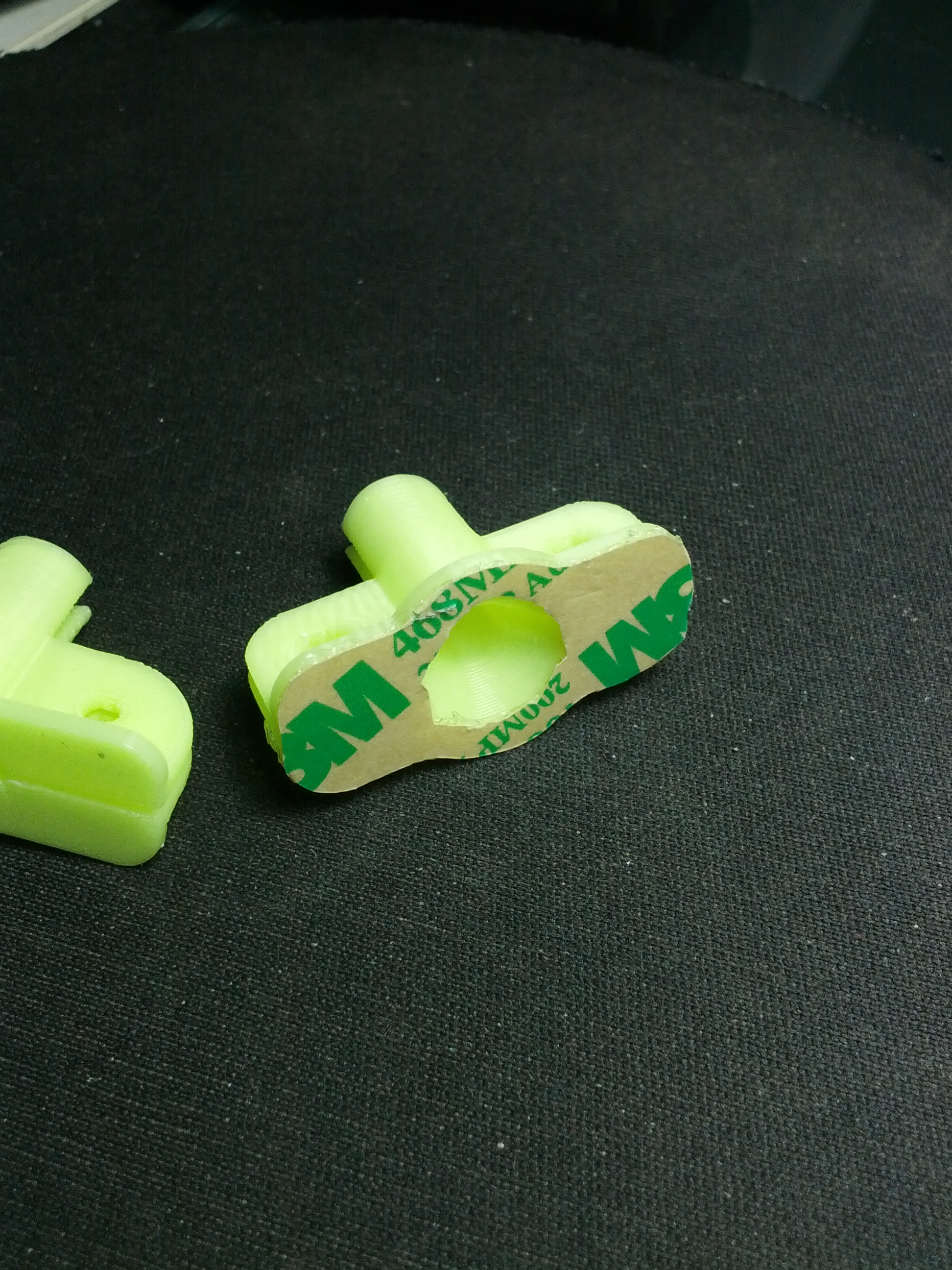
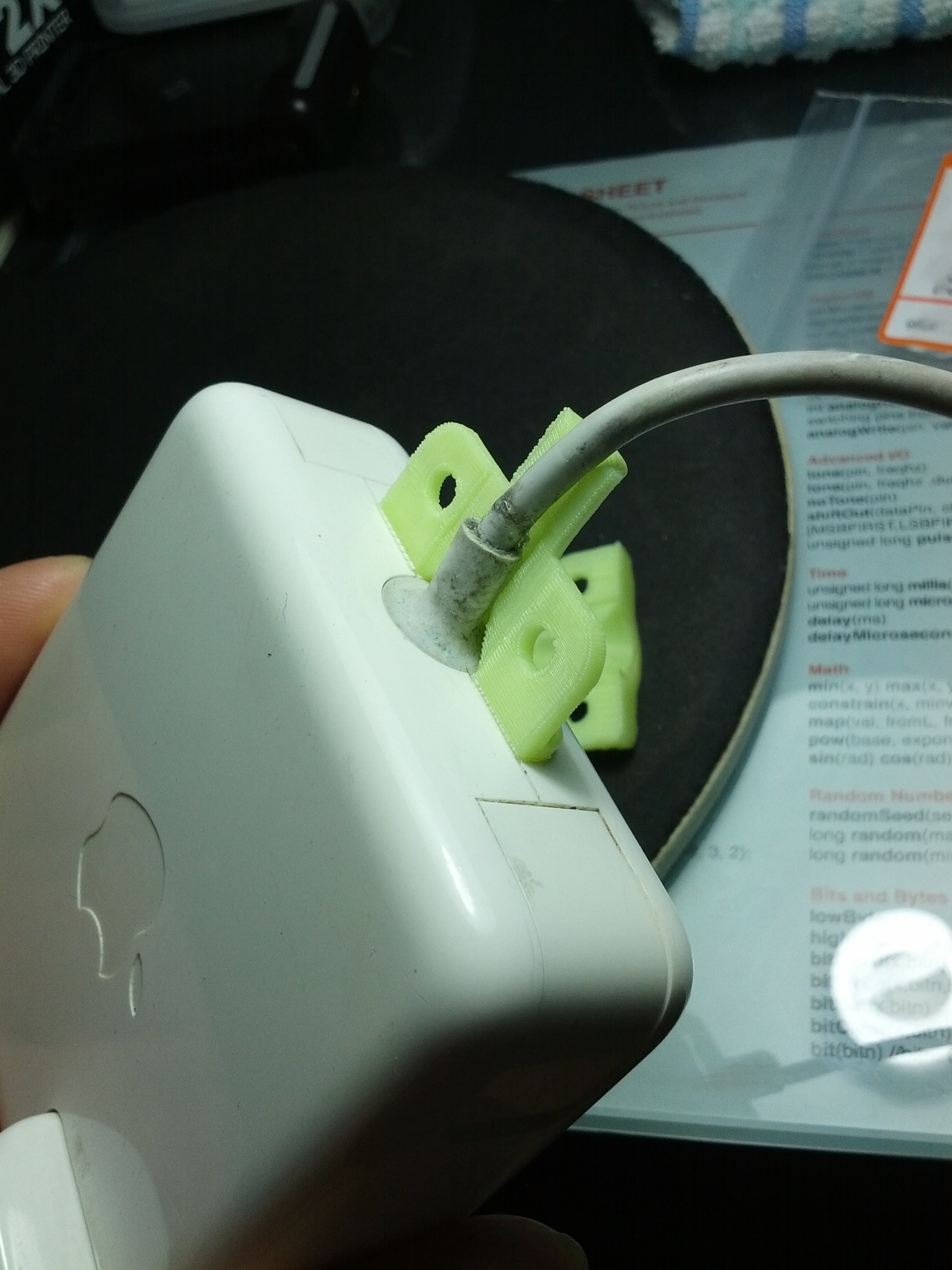
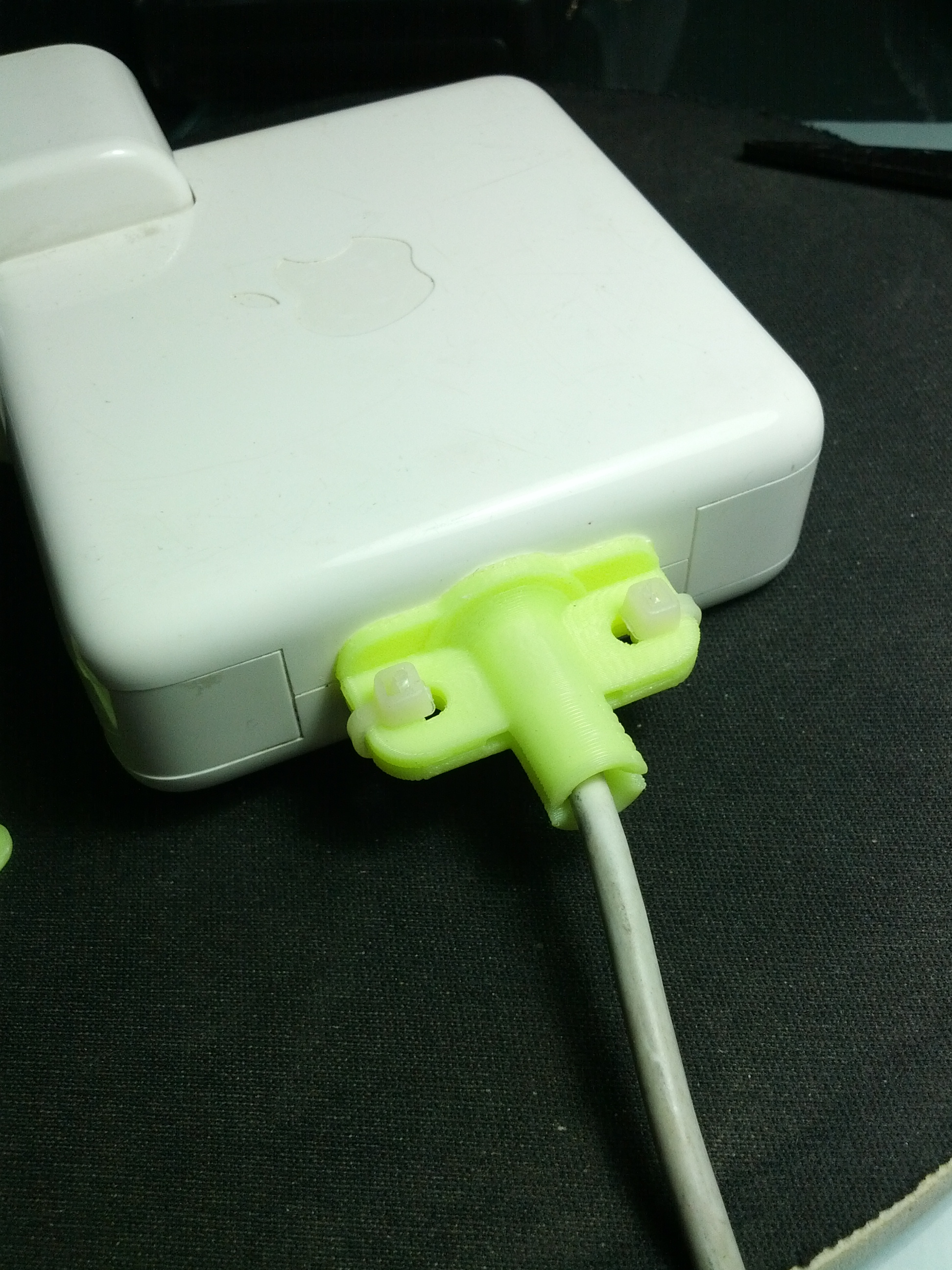
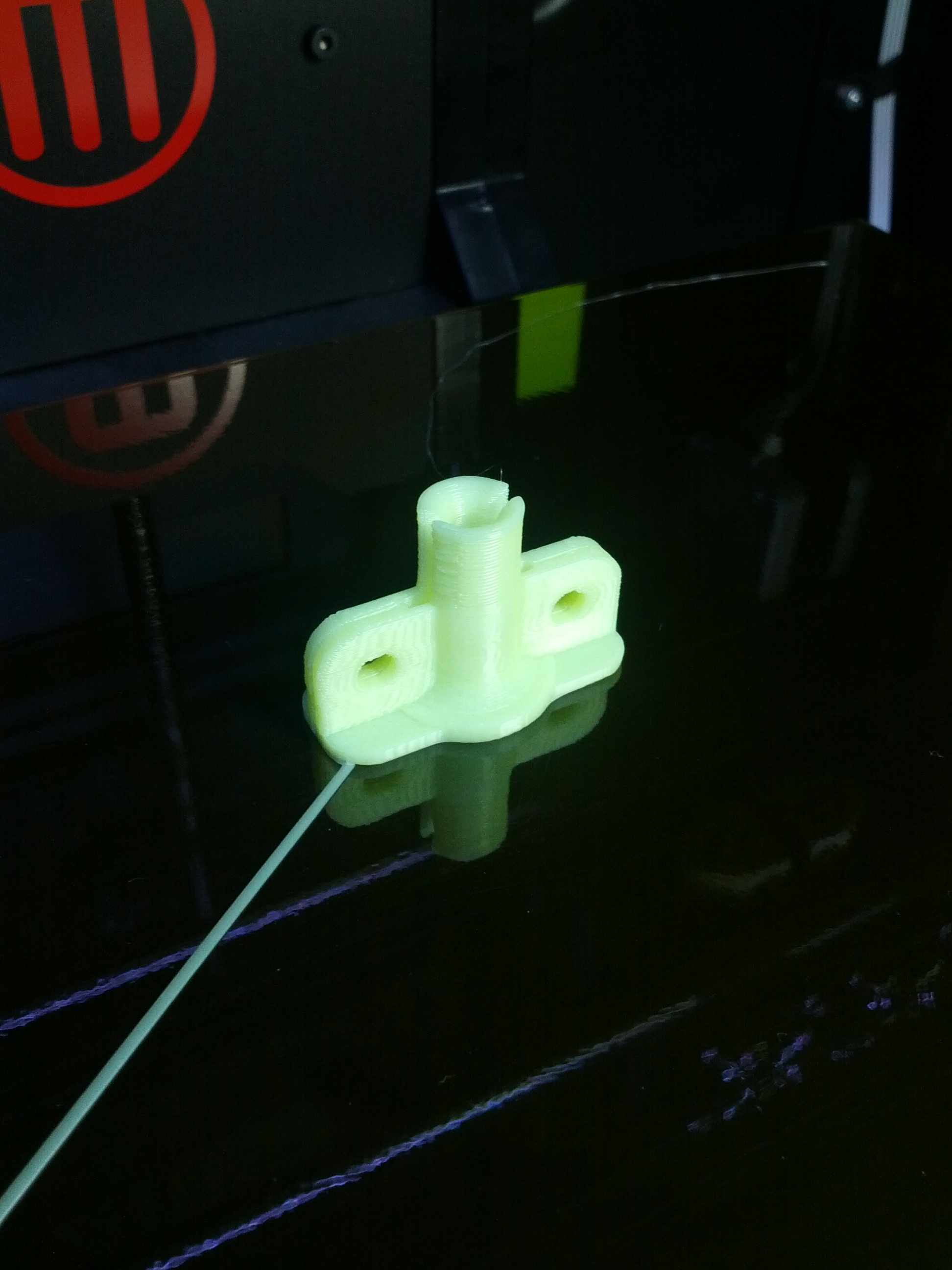
1. Attach a layer of 3M Double sided adhesive
2. Detach the two parts and attach half of the unit with the adhesive tape peel off.
3. Attach the other half
4. Use two cable ties to tighten the two pieces.
Thanks for reading. Hope to hear some feedback and improve it.
Anthony L (MILKA)
2. Detach the two parts and attach half of the unit with the adhesive tape peel off.
3. Attach the other half
4. Use two cable ties to tighten the two pieces.
Thanks for reading. Hope to hear some feedback and improve it.
Anthony L (MILKA)