Apple HomeKit Wi-Fi Dehumidifier Based on ESP8266 💧
by HomeKid in Circuits > Apple
10396 Views, 30 Favorites, 0 Comments
Apple HomeKit Wi-Fi Dehumidifier Based on ESP8266 💧
Unfortunately there are only one or two DeHumidifiers out there that supports Apple HomeKit, but these have a really high prices (300$+). So i've decided to make my own Wi-Fi capable Apple HomeKit Dehumidifier based on a cheap one I already have 😄
It can work natively with HomeKit using ESP8266 so no homebridge, HAP-NodeJS needed! 😄
Since the code is very complex and i've used a lot of custom libraries I've made pre-compiled firmware files. For those who interested in making native HomeKit projects, the source code for esp-homekit available here. If you don't want to use my firmware, the GPIO pinout is available below for making your own one 😊
For more information visit the related GitHub page! 🤓
Features:
- Humidity Measuring using SHT3x sensor
- Set up Target Humidity
- Controlling fan speed
- Water Level (via LEDs and auto power-off when Tank is full)
- Power/Reset Button
PCB Parts:
- ESP12F/E/S
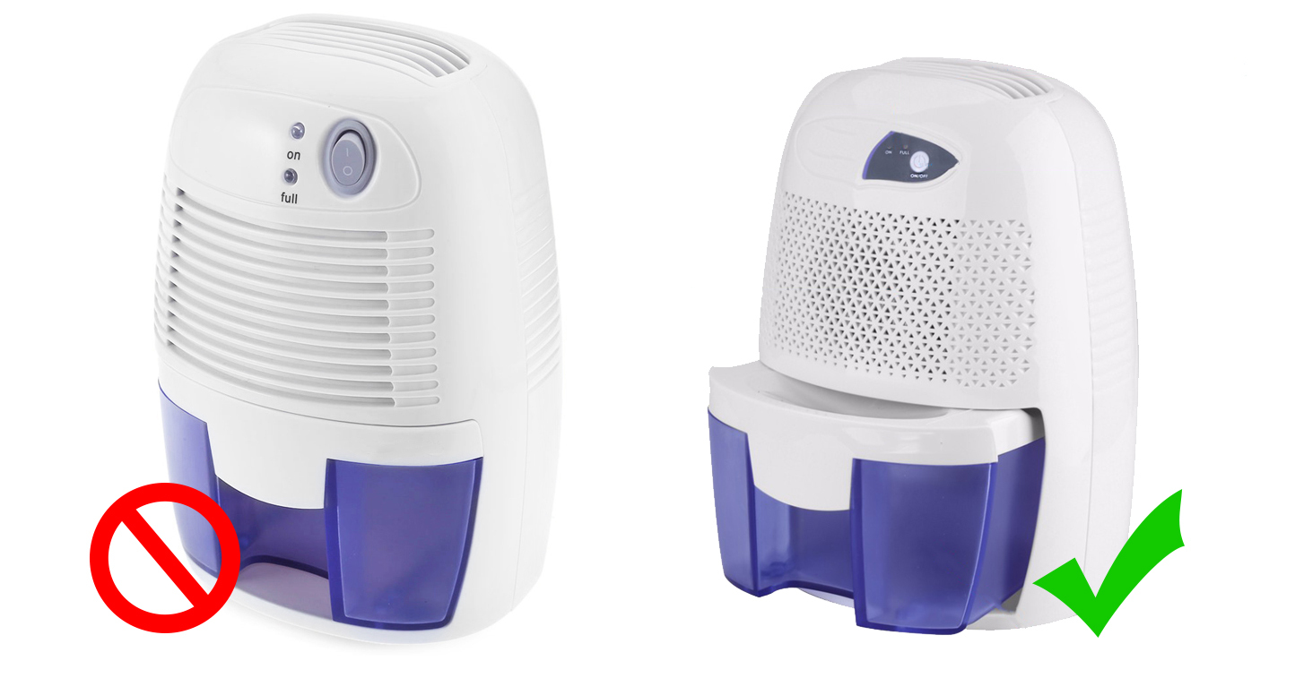
- XROW600B Dehumidifier
- SHT3x Temepreature/Humidity sensor
- SMD 0805 resistors
- SMD 0805 capacitors
- AMS1117-3.3
- Tactile Button
- 1x4P 2.54mm header (optional)
- IRF540NS
- SMD 10x10.5 50V 100uF Capacitor
- SMD 6x7 6,3V 330uF Capacitor
- LM2575S-5.0
- 330uH CRDH74 inductor
- 1N4007 diode
- 2N3904
- VH3.96-2P
- XH2.54 2P, 4P, 5P
- 3MM Red/Green LED
- 3mm (height) LED nylon spacer
- 4P Male XH2.54 with cable (for humidity sensor)
Supplies
- Soldering Iron OR Soldering Station OR Hot Air Soldering Gun
- For uploading the code you probably have to buy an USB TTL adapter too.
- For disassembling the Dehumidifier you'll need some screwdrivers.
- Custom PCB
- XROW600B dehumidifier
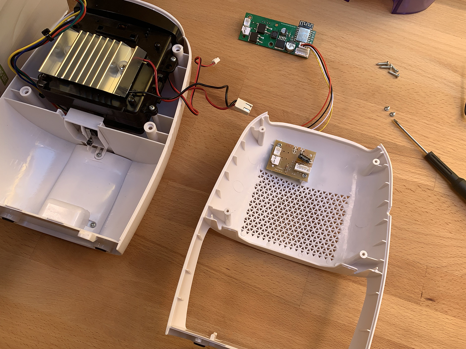
Disassembly
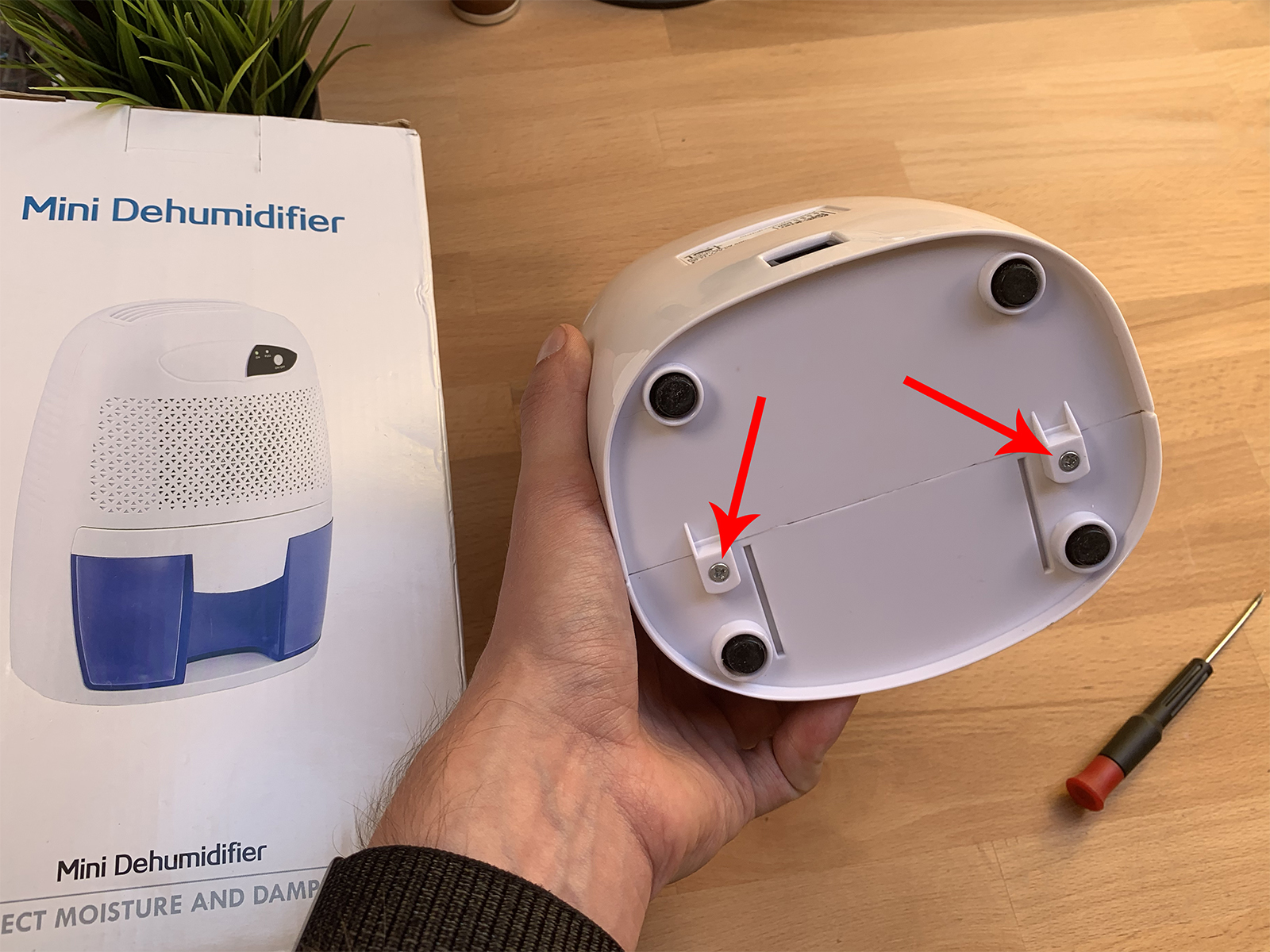
To disassemble the Dehumidifier the only thing you'll need is an screwdriver which can fit in the holes at the back of the device! 😄
- Unscrew the 2 screws at the bottom of the device
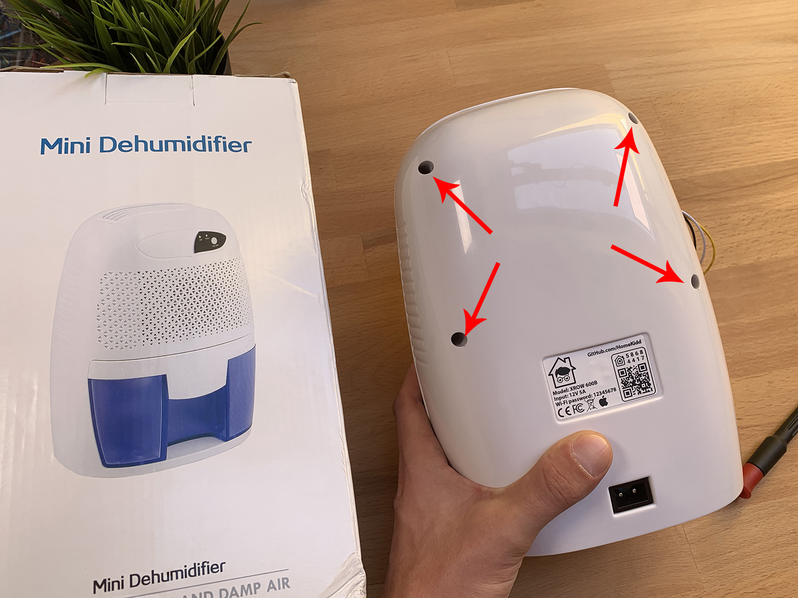
- Unscrew the 4 screws at the back of the device
- Now you can take apart the plastic housing
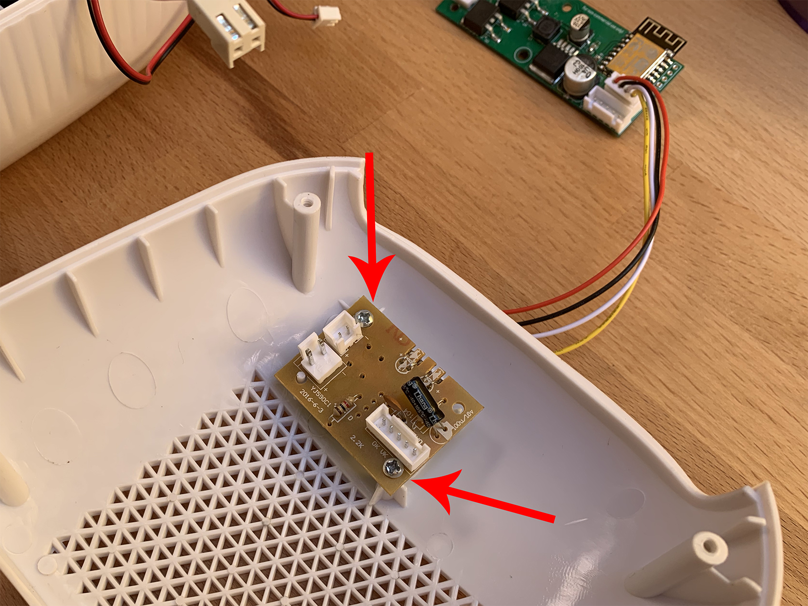
- Unplug every connector on the PCB
- Unscrew the 2 screws that holding the PCB
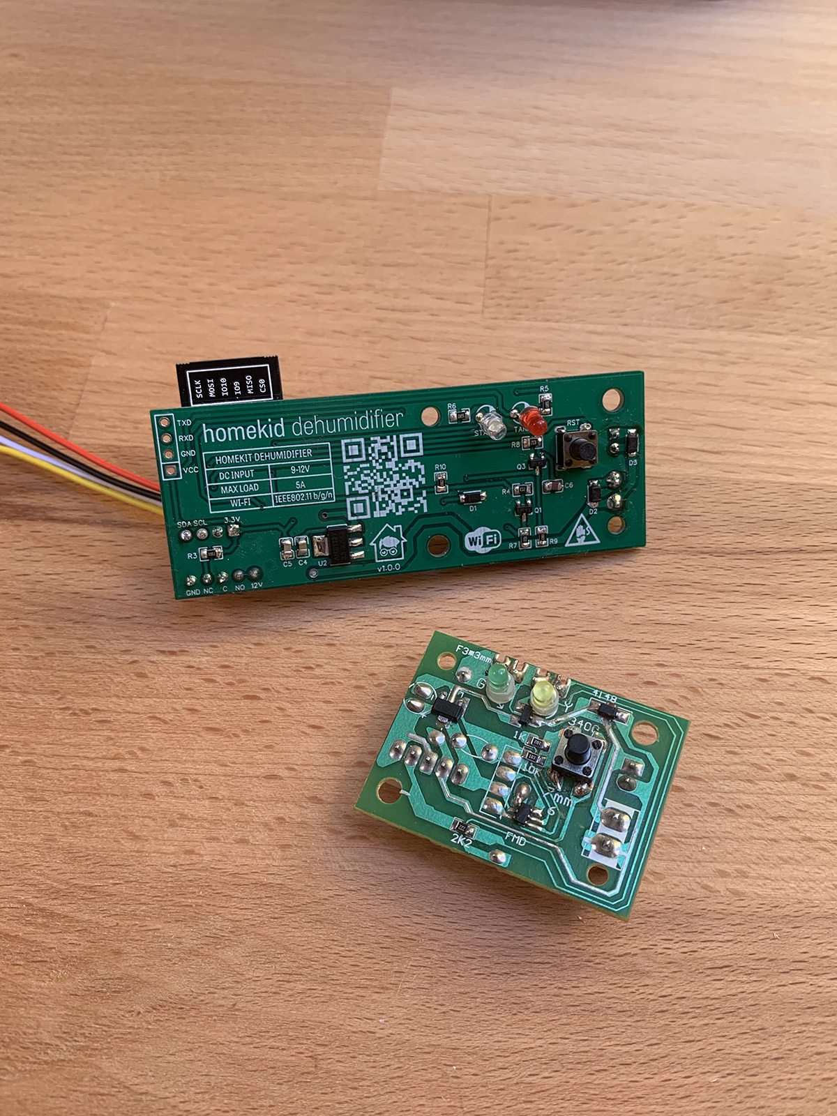
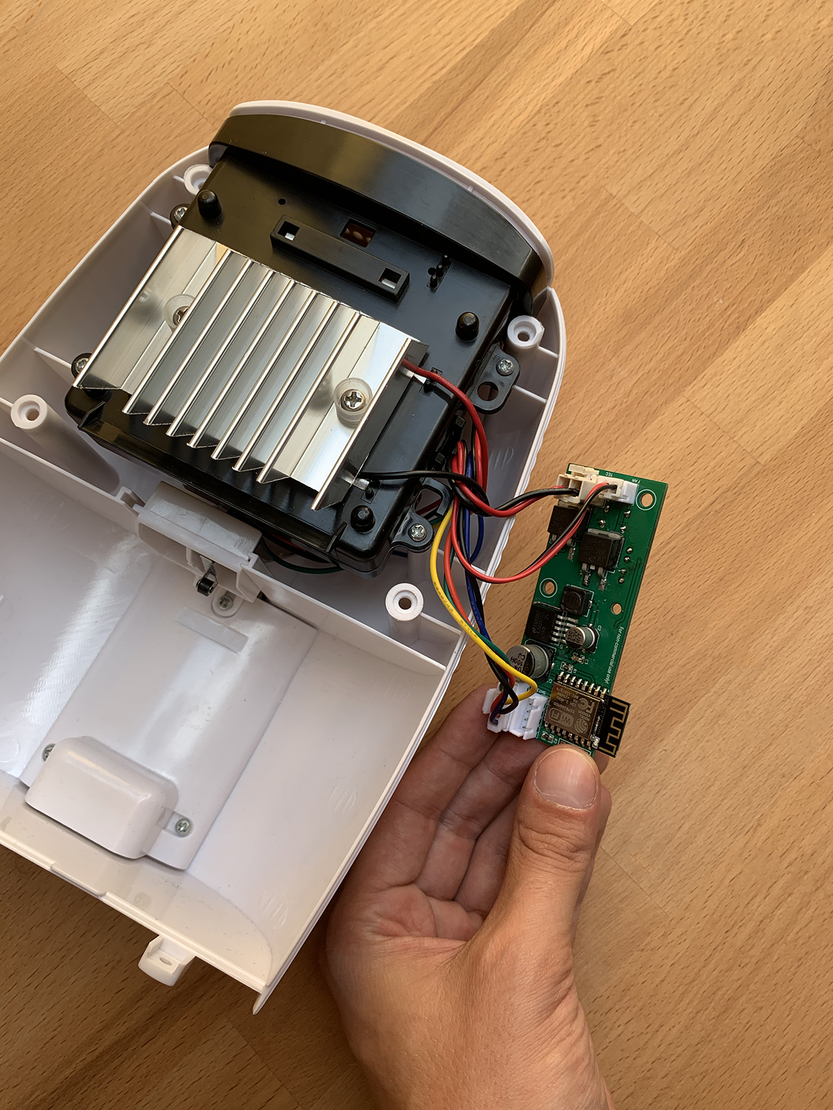
Custom PCB


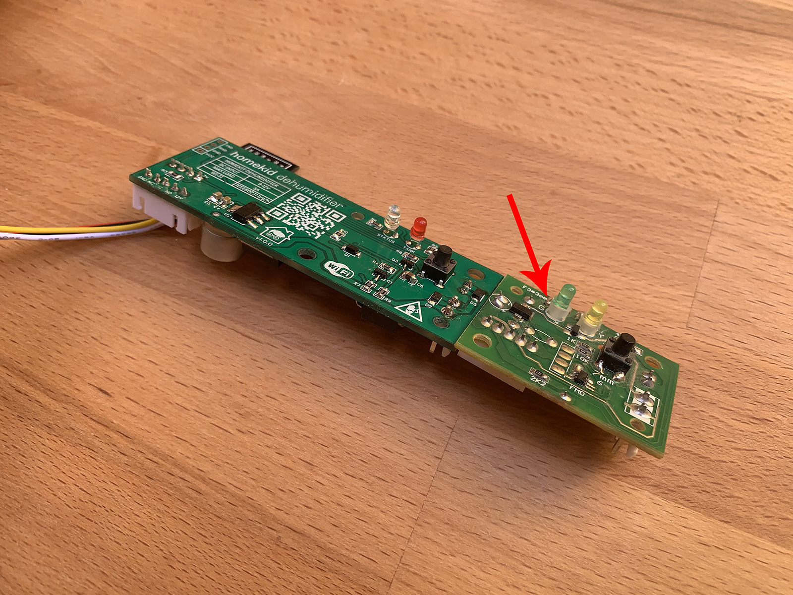
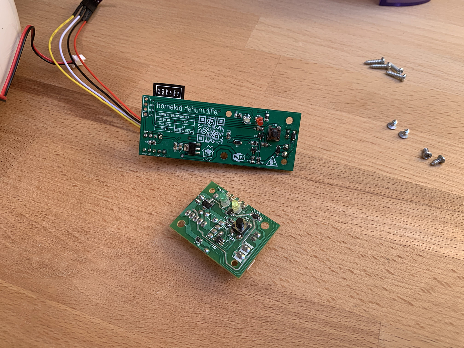
I've designed a custom PCB which can replace the original, very basic one. Its basically just a power supply / step-down converter from 12V to 3.3V, two MOSFETs for driving the fan and the peltier, the ESP8266 itself, two LEDs and the tactile button like on the original one.
I've also added the same connectors for the new PCB as on the original one and an extra 4 pin connector for the SHT3x Humidity sensor. The 9V power supply that comes with the Dehumidifier also can be used! Everything is plug 'n' play 😄
You can find more information about the PCBs here!
PCB files can be found at PCBWay!
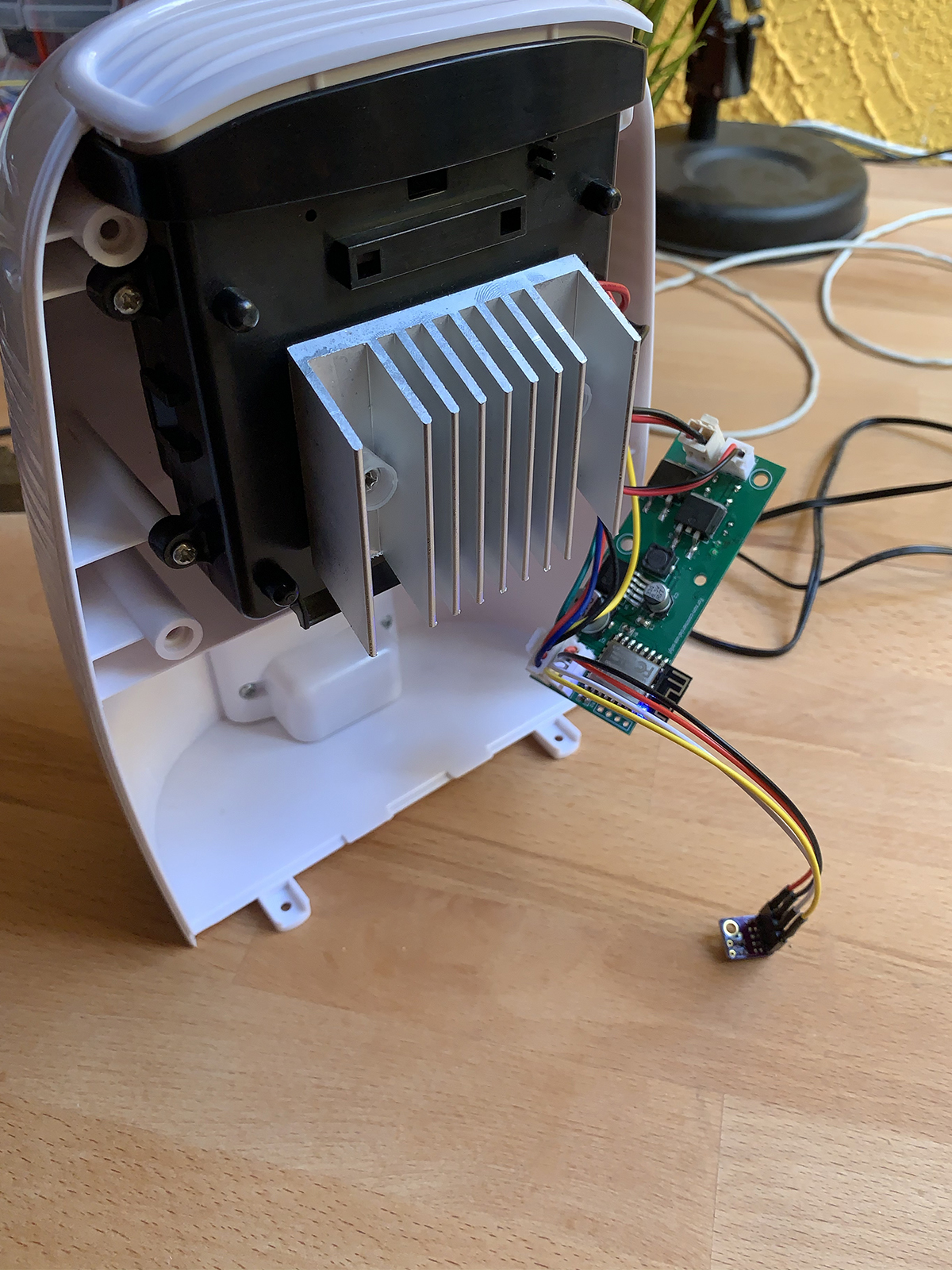
SHT3x Humidity Sensor
You have to wire up the SHT3x sensor using a male XH2.54-4P connector with wires (linked at the part list) simply connecting up everything as it should be: VCC to VCC, GND to GND, SDA to SDA and SCL to SCL 😄
Currently in my setup the sensor is just hanging outside the dehumidifier's case, its up to you where/how you place the sensor but inside the dehumidifier's case the caught humidity/water may influence the sensor reading! 😄
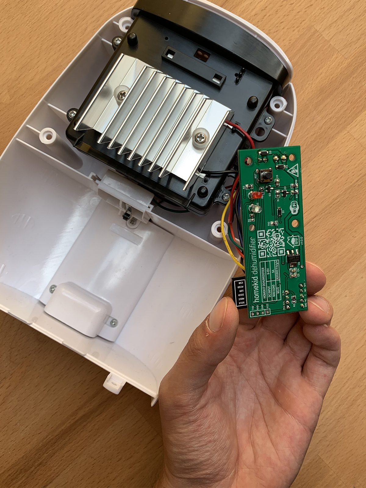
GPIO Pinout
If you want to use your own firmware heres the pinout:
- Button - GPIO0 (D3 on wemos D1 mini)
- SHT3x SDA - GPIO4 (D2 on wemos D1 mini)
- SHT3x SCL - GPIO5 (D1 on wemos D1 mini)
- Built-in LED GPIO2 (D4 on wemos D1 mini)
- Power LED - GPIO14 (D5 on wemos D1 mini)
- Fan - GPIO15 (D8 on wemos D1 mini)
- Peltier - GPIO12 (D6 on wemos D1 mini)
- Tank sensor - GPIO13 (D7 on wemos D1 mini)
Software Setup
You can download the firmware from my GitHub page!
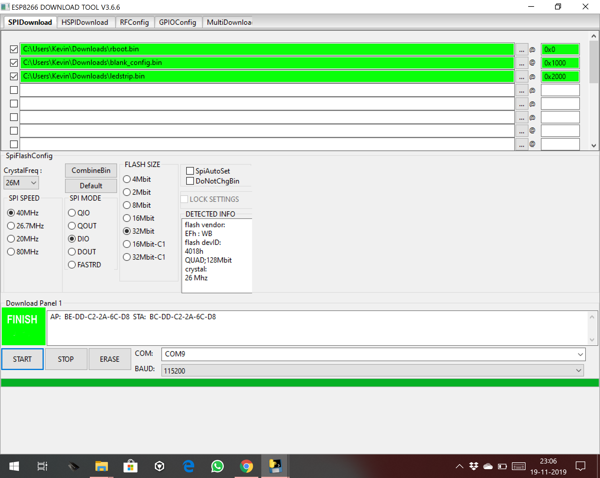
Windows
For Windows you can use the official Firmware Download Tool by Espressif!
Setting the flash addresses (0x2000), flash size (4MB/32mbit) and flash mode (DIO/QIO) is very important step, but these settings may changed based on the module you're using! Also I've recommend to erase the flash when you first time install the firmware before uploading the .bin files!
Settings:
- Baud rate 115200
- Flash size 4MB or 32mbit (depending on your module)
- Flash Mode QIO (or DIO, depending on your module)
- 0x0000 rboot.bin
- 0x1000 blank_config.bin
- 0x2000 main.bin
- 40MHz
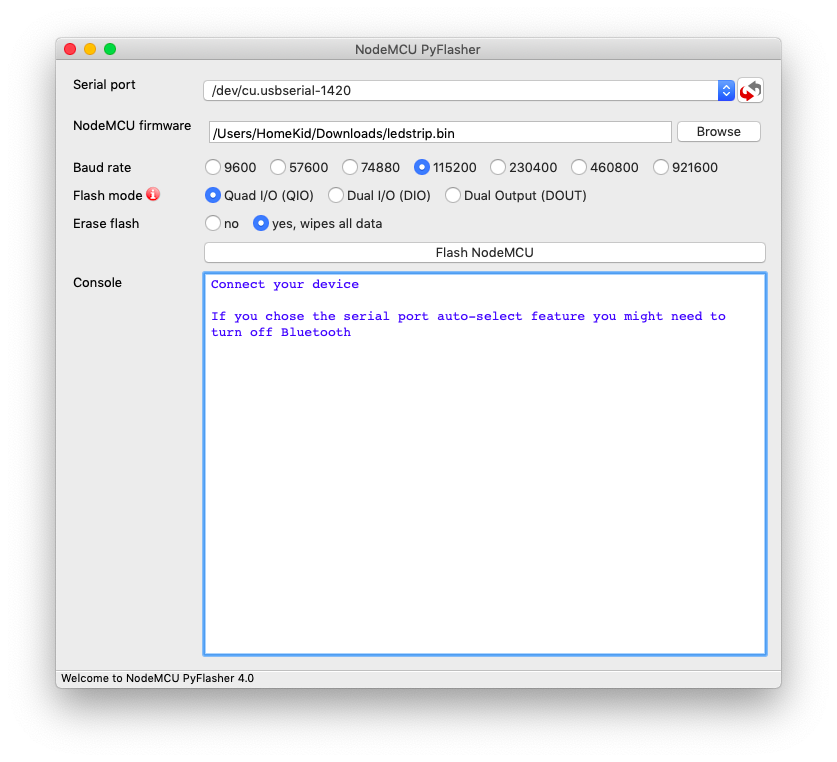
MacOS
For MacOS you can use this flasher tool!
- Settings: Erase flash - yes (only on first time install)
- Baud rate 115200
- Flash size 4MB or 32mbit (depending on your module)
- Flash Mode QIO (or DIO, depending on your module)
- File: main.bin
- 40MHz
Manually Flash
We have to install esptool.py on our Mac in order to be able to flash our ESP module. To work with esptool.py, you’ll need either Python 2.7, Python 3.4 or a newer Python installation on your system. We recommend using the latest Python version, so go to Python’s website and install it in your computer. With Python installed, open a Terminal window and install the latest stable esptool.py release with pip:
pip install esptool
Note: with some Python installations that command may not work and you’ll receive an error. If that’s the case, try to install esptool.py with:
pip3 install esptool python -m pip install esptool pip2 install esptool
After installing, you will have esptool.py installed into the default Python executables directory and you should be able to run it with the command esptool.py. In your Terminal window, run the following command:
esptool.py
With esptool.py installed on your computer, you can easily flash your ESP8266 board with the firmware. At first you need to download three bin files: rboot.bin and blank_config.bin and the latest release. The rboot.bin contains the bootloader for the ESP8266 and the blank_config.bin in just a blank config file and ledstrip.bin contains the firmware. Now connect your device to your FTDI adapter in flash-mode.
To enable ESP8266 firmware flashing GPIO0 pin must be pulled low while powering the device. With my custom PCB theres a button, which you need to press and hold while connecting the FTDI adapter to your PC. Conversely, for a normal boot, GPIO0 must be pulled high or floating. Start in FLASH MODE Go to the directory you made where you put the previously downloaded rboot.bin blank_config.bin files (e.g Downloads) Open the Terminal app. Click the Finder icon in your dock. Click Go. Click Utilities. Double-click Terminal.
Change to the downloads directory.
Note: If You using an another library for storing the three .bin files, navigate into that library using `cd` command: Use esptool.py to flash your device.
cd downloads
You'll need an USB TTL adapter for connecting to the ESP8266. If You using a Wemos D1 Mini only needed is a microUSB cable, the Wemos has TTL adapter built-in.
When first time installing the firmware we need to erase the flash:
esptool.py -p /dev/ erase_flash
Normally, your ESPPort will be something like /dev/cu.usbserial-`xxxxxx`. Then, set your device in flash-mode again, and flash the new firmware:
esptool.py -p /dev/cu.wchusbserial1420 --baud 115200 write_flash -fs 32m -fm dio -ff 40m 0x0 rboot.bin 0x1000 blank_config.bin 0x2000 main.bin
Wi-fi and HomeKit setup
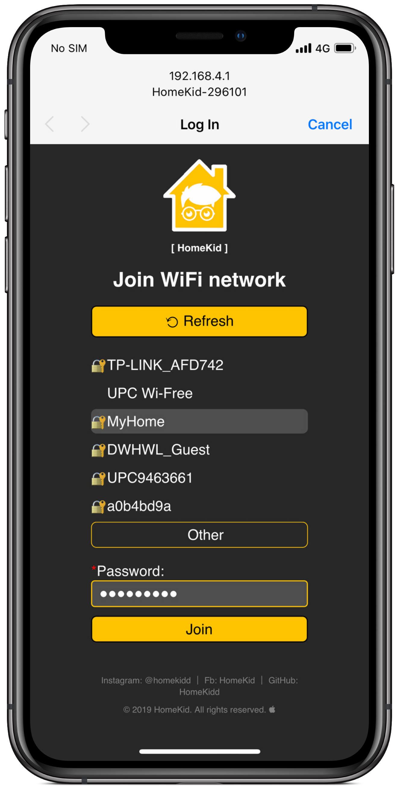
Wi-Fi Setup
You must configure wifi network before adding the accessory to HomeKit. To configure Wi-Fi settings, device generates its own Wi-Fi in AP mode. You must connect to it in order to setup your Wi-Fi network. Simply take your iOS device, go to Setting -> Wi-Fi, and search for an SSID called HomeKid-followed by the module's MAC address and connect to it. For security reasons the AP is password protected!
Default AP password: 12345678
Wait a few seconds until a web appears showing you all Wi-Fi networks that the device has found. Select yours, and enter password! Then click the Join button! The module will try to connect the selected Wi-Fi network, this will take a couple of seconds.
Note: If the given password is wrong, you can Reset the Wi-fi settings by holding the button for 10sec
HomeKit Setup
In your iOS device, open Home App and follow normal steps to add a new accessory. Pairing setup takes about 30 seconds.
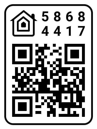
HomeKit code is 586-84-417
Also You can scan this HomeKit QR code.
Note: If pairing fails, you can unpower your device, repower it, and start HomeKit setup again (Wifi settings keep configured). After successful pairing the Power LED will flashing white 3 times!
PCB Connections
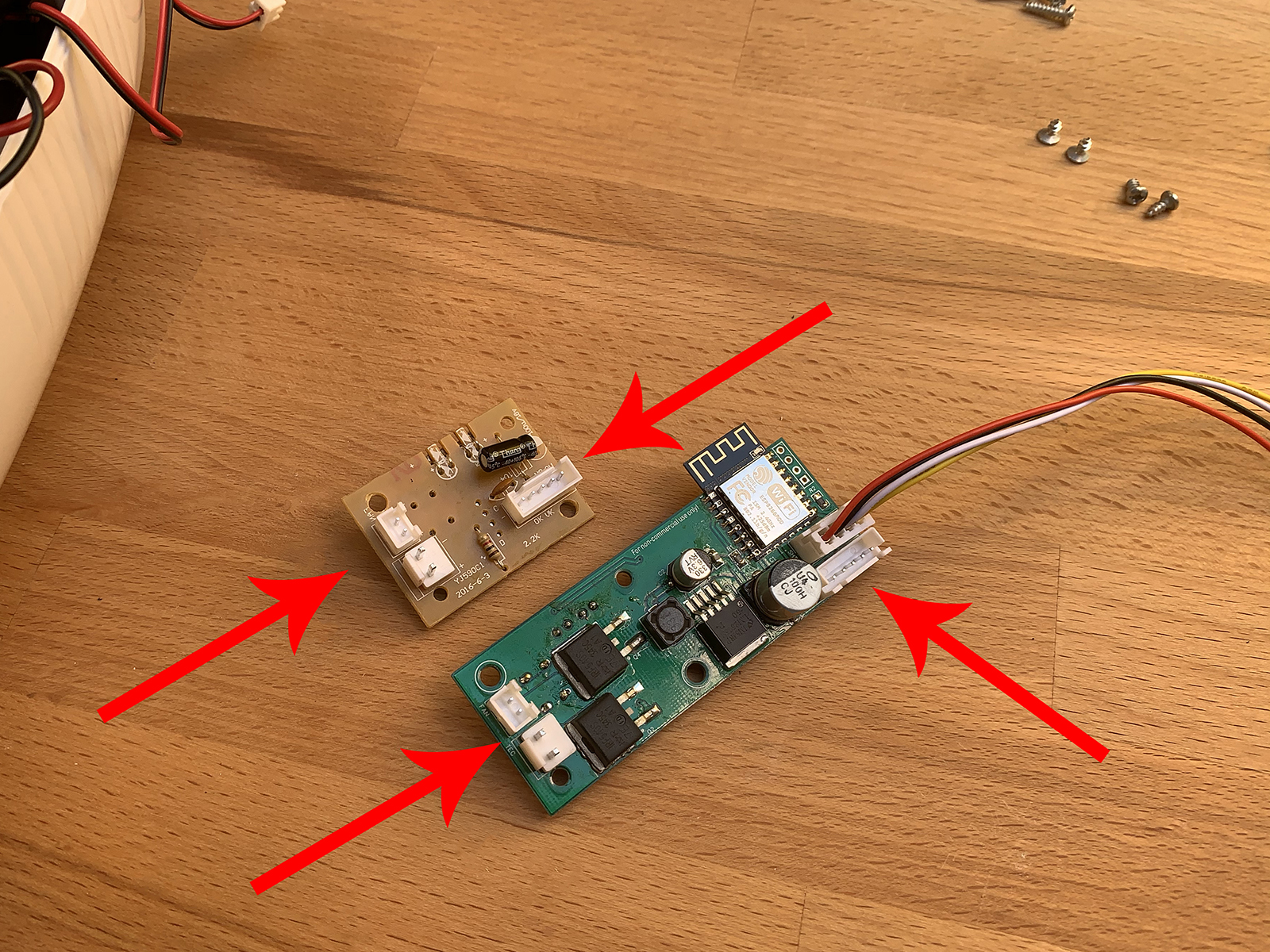
For the PCB design i've chosen the same connectors as the ones on the original PCB! 😄
So this step should be straightforward:
- Connect the Fan to the Fan connector
- Connect the TEC (peltier module) to the corresponding connector
- Connect the 5 pin Power connector to the corresponding connector
- Connect the SHT3x module to its own connector
Putting It Together
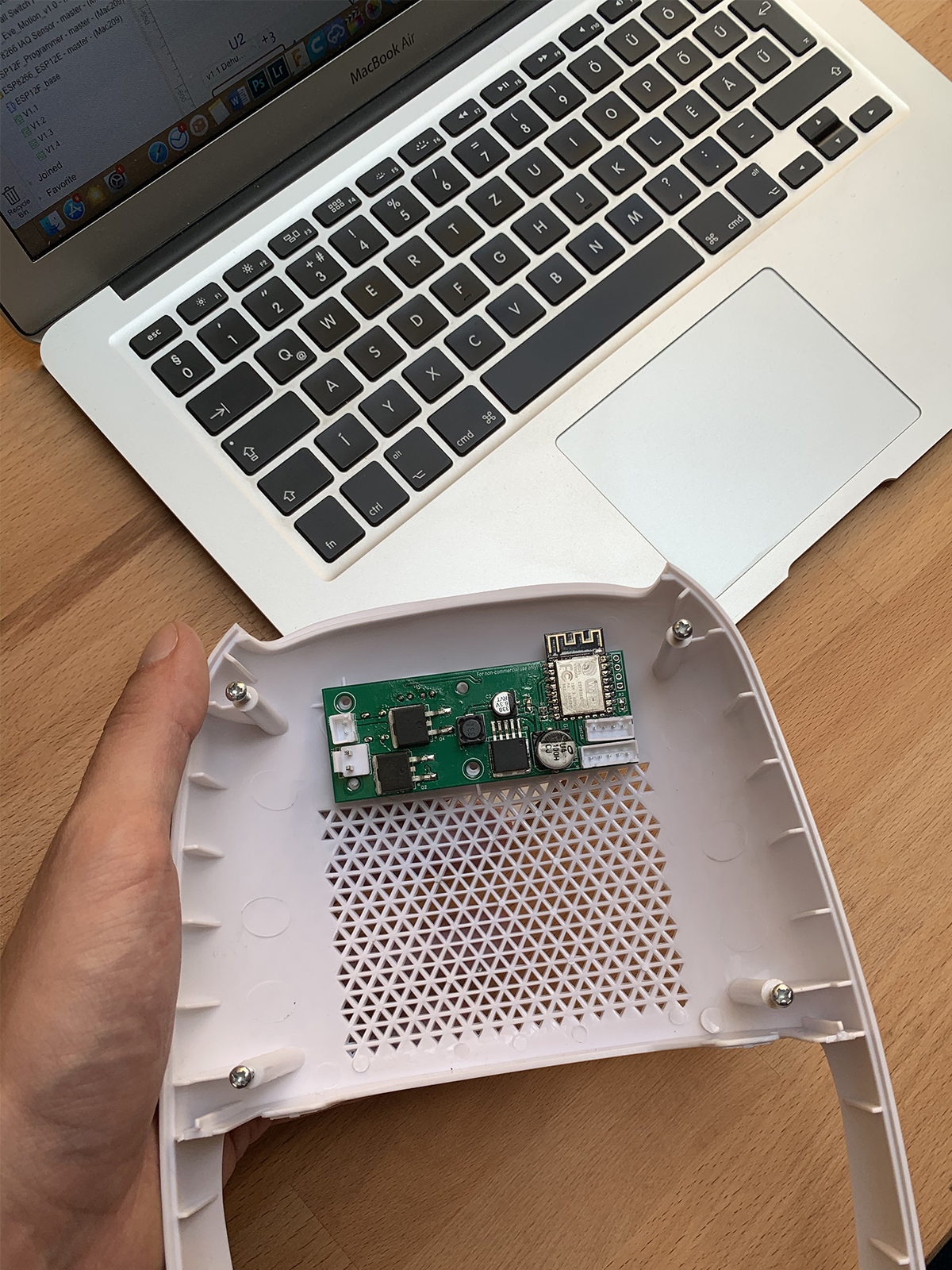
Putting the device together is the same process as the disassembly just in reverse order 😄
Useful Notes 😄
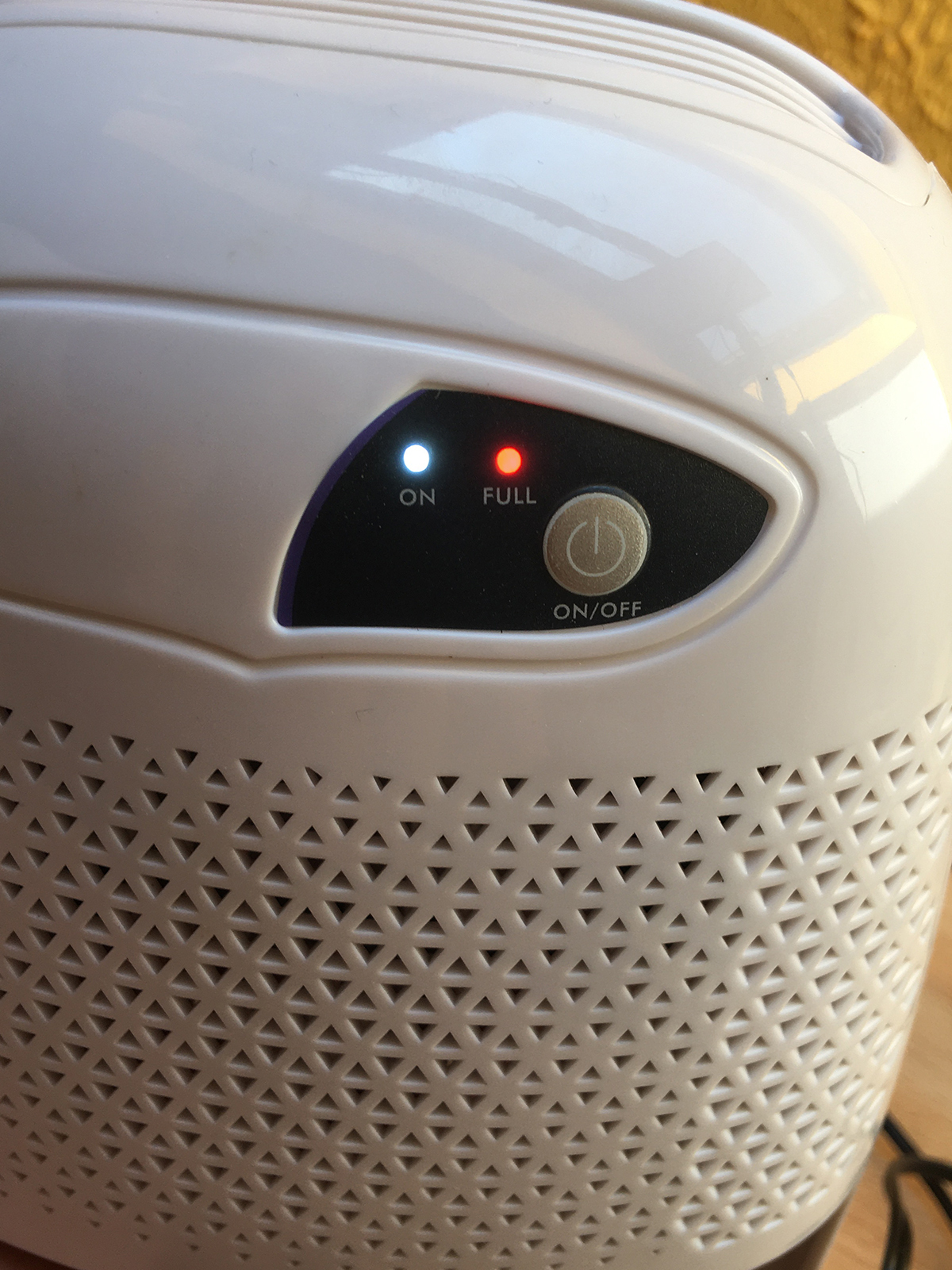
The Dehumidifier has some safety features when the Tank is full and the device is running:
- Automatically shuts down the Fan/Peltier until the tank is empty
- Immediately turns on the red LED
- Flashes the power LED 3 times every 30 seconds
Also has safety feature in case the SHT3x sensor doesn't work properly:
- Automatically shuts down the Fan/Peltier until the tank is empty
- Setting the current humidity to 0%
- Flashes the power LED 2 times every 30 seconds
When both the SHT3x has error and the tank is full the power LED will flash 6 times every 30 seconds.
In the the ESP8266 has some error you don't need to unplug the device from power, triple pressing the button will reboot the ESP8266!
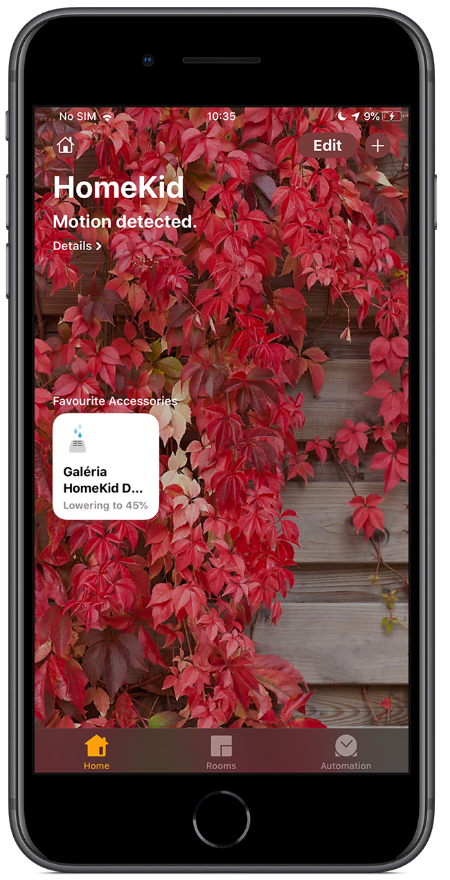
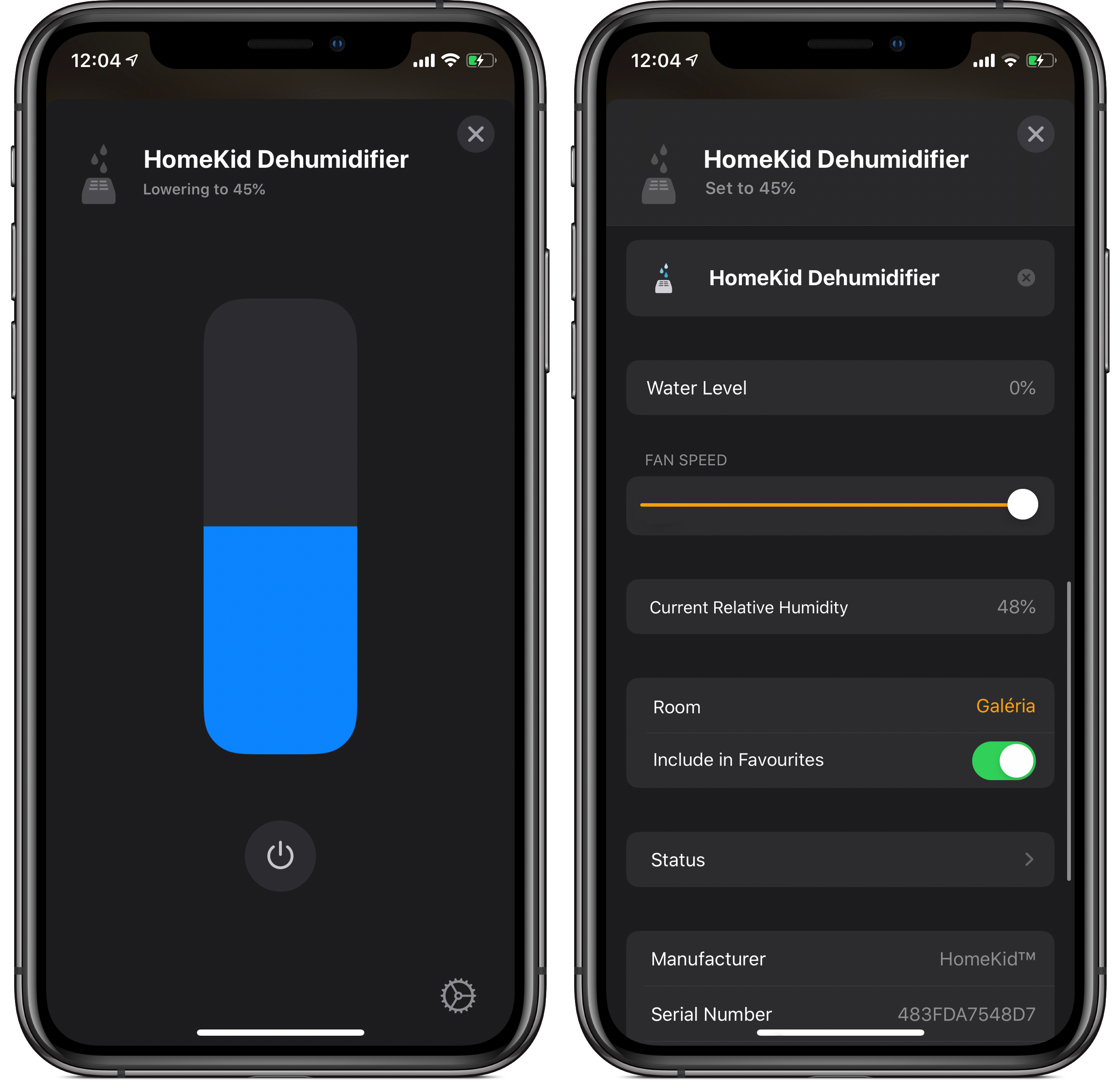
When the Dehumidifier turned on and current humidity is equal and/or less then the target humidity, the device will go into Idle mode. In the Home app it will show "Set to ..." when the device is idling and shows "Lowering to..." when its running!
Updating the firmware
I've planned to implement Over-The-Air (OTA) firmware updates but it isn't that reliable so updating should be done manually like at the first setup! The only difference is you don't need to erase the flash, by simply flashing the newer firmware without erasing it will preserve your Wi-Fi / HomeKit settings! 😄