Anti Bruxism/Teeth Grinding Device (arduino Based)
by Tokupa in Circuits > Wearables
7321 Views, 38 Favorites, 0 Comments
Anti Bruxism/Teeth Grinding Device (arduino Based)

About three years ago, my dentist pointed out that I am suffering from bruxism (the clamping kind, not the grinding type). He could tell, since he saw my teeth have cracks in them. This of course didn’t sounded too good to me… Especially since I like my teeth.. I never had any holes in them and I definitely did not want to start now. So far the cracks were not too serious, but it might well turn out to be over time. Thus, it is tinkering time!
Before you read further, please know that this tutorial has been as a ‘to be finished’ on my computer for a long-long time. In the end I simply finished it. So although this instructable could be better I still hope that you enjoy it.
I am not going to write a medical journal on the topic as obviously a lot of information can be found on the internet. Bruxism is not fully understood (including the cause) and a simple solution to prevent it is not really out there. Please see the URL links down here for some quick information on bruxism and some nasty pictures of the possible results on your teeth.
http://www.mayoclinic.org/diseases-conditions/brux...
After the diagnose of my dentist I noticed that I actually clamped my teeth a lot of times during the day. The simple solution: just stop doing it! Although it is hard to break a bad habit, it worked. Unfortunately I (actually, the majority of people) mostly clamp/grind their teeth at night. Breaking this habit during sleep is somewhat harder (actually impossible..) since I am simply not aware that I am doing it.
My dentist gave me a specially adjusted mouth guard which should help. I can see how this helps protecting your teeth when grinding. I don’t think it actually helps when clamping since the used force will simply be transferred through the mouth guard from lower to upper teeth (albeit somewhat distributed and thus likely result in less pressure per teeth). So it would be nice to stop the clamping altogether. And that is what this Instructable is about: How to assemble an arduino based device to prevent bruxism by changing your behavior (with a Pavlov reaction).
The Idea of a device like this is not an original idea of me. The way of execution is however my idea and I have not simply copied somebodies project. However, I have of course ‘borrowed’ bits and pieces of others. It is mentioned in the instructable where this is the case.
Some other homemade bruxism devices are:
https://sleeptrack.io/2013/04/01/development-of-gr...
https://github.com/lucwastiaux/gc
There is at least one commercial product I am aware of which I like to list here for the people that want an off the shelf solution:
http://mysleepguard.com/sg-international/
For my bruxism device I have chosen to measure the activity of my yaw muscles to see if I am clenching. I could have chosen to simply measure the clamping force in a mouth guard. This did not seem a good idea to me because having a battery in my mouth, while clamping.., did not sound to appealing. Nor do wires sticking out from my mouth. Furthermore, measuring muscle activity sounded like a challenge. Could I make that work? Mainly because this is my first Arduino project, some serious tinkering was involved. And I liked it! :)
The main idea of the project is this: measure if I am clamping. If yes, then generate a sound with increasing volume. The sound then should trigger a Pavlov reaction, so I relax the yaw muscles. If I don’t relax I will eventually wake up. The longer you use it the better the pavlov reaction should work. I want to measure if any improvement arises, so measured data is saved on a SD card for later investigation. To see any difference, of course first a baseline measurement has to be performed, which is simply not using the feedback of the sound and only saving the measured data.
Before we get started, I would like to mention this: Of course some people will (correctly) mention that a common cause of bruxism is probably stress. So the chain of thought might be: stop stressing and the bruxism will disappear. The problem is that even if the trigger for bruxism (e.g. stress) is gone, the bruxism can already be a habit and very hard to break. Especially during your sleep when you are not conscious of the fact that you are doing it. Furthermore, some people simply have some kind of stress in their lives. This might not even be a bad thing, as long as this will not cause mental or physical problems.
The End Result First....


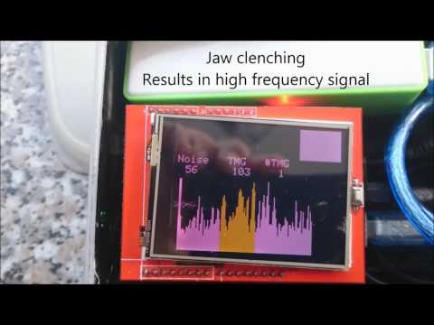
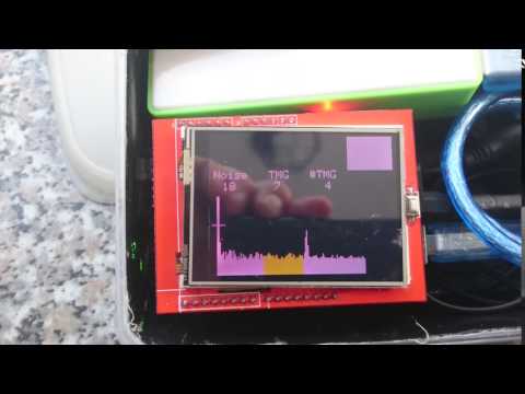
Please take a look at the pictures and the movie to see what the end result has become. The picture explains what is seen on the touch screen. With that in mind I think the video is pretty self explanatory.
What you should know is this:
- Increase in the frequencies in the yellow part is used to measure the muscle contraction from the jaw clenching.
- The white part to the left (of the yellow), are lower frequencies. Movement without muscle contraction is seen as an increase in this part and not/less in the yellow part.
- A beeping sound is heared when it measures jaw clenching. The sound increases in volume and duration if the jaw clenching continues
- I have hold one earpeace close to the microphone of the camera to hear the beeping sound. This did not work out too well. Maybe you should increase the volume of your computer speakers. Also, in reality it is more of a beeping than a grinding.
Overview and List of Parts


This tutorial might also help you with your (totally different) Arduino project on the different subjects this instructable tries to cover:
- Tips and Tricks on the Olimex EEG shield
- Tips and Tricks on the cheap 2.4” TFT touchscreens (in combination with the Olimex EEG shield)
- Signal filtering with the use of FFT on an Arduino
- Sound generation with software volume control without the use of a library
- Using interrupts on an Arduino
- Using SdFat library for writing and reading your SD-card
- General tips on making a smaller script, so it will still fit in the memory of your Arduino.
List of parts:
- Arduino Uno
- Olimex EKG-EMG shield + wiring
- Piezo buzzer or headphone extender cord (with volume control) and headphones.
- 2.4” TFT touchscreen (with SD-card reader)
- SD-card
- Headband + wiring
- Plastic/rubber glue
- EEG stickers
- USB battery + USB cable
- Conductive gel/cream. A bit of saliva will also work fine.
- Box to put everything in. Make sure the box does not let out any light which can be annoying at night.
The project needs a surprisingly low amount of homemade parts. The headband and the EEG stickers will be merged together to form the reusable sensor that can be put around your head. The piezo buzzer or headphones must be connected to the Arduino. More on those subjects later. The rest is actually ‘just’ programming work. As said, since this is my first Arduino project, this programming cost me quite a lot of time and work. I tried to keep the programming as neat and small (computational and memory) as possible, but this certainly did not result in “big boy code”. Any tips to cleaner and smaller code are much appreciated.
Measuring Muscle Activity


As far as I know there are several shields for the Arduino which can measure muscle activity. I have chosen for the Olimex EMG shield, because it doesn’t require soldering or a different/second power source. Also there is some information on the internet to get you started and conveniently this shield can be matched with the 2.4” TFT touchscreen pin layout.
When using the example scripts I was able to measure my heart with relative ease. For this example the Arduino with shield is connected to the computer, EMG stickers on my chest and a bespoke program, which is running on the computer, shows the heart signal. The arduino and computer software can be found here: https://www.olimex.com/Products/Duino/Shields/SHIELD-EKG-EMG/
The program on the computer takes care of the noise in the signal, which is a common problem with EMG measurement. For this project the Arduino must be working stand alone and not connected to a computer. In the rest of the project I noticed that the noise of the signal is significantly reduced if the Arduino with EMG shield is powered from battery and not connected to the computer and farther away from interfering electronics. The TFT screen can be used to show measured signals and have a better feedback when building or using the device.
For the device to be standalone, the Olimex example script was the starting point. At first the example scripts were quite daunting to me. Until I realized that it is simply possible to measure a muscle activity signal on the pin A1 to A5 (you can choose this with a jumper on the shield).
Headband


For an EMG measurement there are three electrodes necessary. Two for measuring the electromagnetic pulses (usually red and white) and a ground (black). For testing purposes I measured the muscle activity of my biceps because this muscle gives a very clear/distinct and easily measured signal. I started out with using the sticky electrodes, but soon created my very improvised but reusable electrodes out of three used sticky electrodes and an old sock.
Use a sock that has an open kind of fabric. I used an old sport sock type. Cut the toes of your sock so you can put your arm through. Glue the electrodes from the inside while letting the clips stick through your sock. It does need a little bit conductive gel to work correctly. You can put some salt in hand cream, or just use some saliva.
After you have made some successful EMG measurements, try to find the optimal spots for your electrodes to measure the jaw clenching signal. Then use the same principle as the sock to create the headband. It surprised me how good this setup works.
TFT Touch Screen Shield

These little screens are great! But at the same time a PITA to get them working! Right now I have bought three of them over some period of time, and it seems that the specifics of these shields change for all three. Granted, they all work but it took me a long time how to get so far and probably don’t understand the specifics. Trial and error (and Google) (tri-oogle and Err-oogle) has been my approach here. And when finally the script was correct to get one screen working, the touch of the others don’t work. Or the orientation is wrong or... If anybody has some background information on why this is or how to do it better, please let me know.
[simple Touch screen script]
Please note that these screens are actually a TFT-screen with a resistance-sensor on top for the touch screen. That means at least two things:
- The x-y coordinate you get from the touch sensor do not automatically correspond to the correct x-y values of your TFT screen. Meaning: the touch screen gives a value between 0 to 1024 (but differs per screen. Mine between 207 -915 in x direction, and 200-920 in y direction), while my screen has a resolution of 0 to 340 and 0 to 240.
- The orientation of the touch sensor will always be the same, even when changing the orientation of the TFT screen (for example with the function tft.orientation(x), where x can be 0 to 3). In my project this means that:
- x-coordinate touch sensor = y-coordinate TFT screen
- y-coordinate touch sensor = minus-x-coordinate TFT screen
I found that the differences between the screens I have are:
- Different chip used: This means that in reality you have to choose a different ‘identifier’ in your script. I understood that most of the times the identifier can be read from the chip. With one of my screens this is however not possible. I resolved this by trying all the identifiers I could find for these screens until one worked.
- Different pin usage on the Arduino: This can be resolved by setting the correct used pins in your script.
- Different orientation between Touch sensor and the TFT screen: This may result in up is down, left is up etc. This can easily be resolved in the script.
- Different min-max value used by the touch sensor: As said; in principle the touch sensor gives back a value between 0-1024. However, the used min max values which correspond to the TFT screen may differ. . For easy conversion between the touch coordinates and the TFT coordinates the function “map(x, min_val_in,max_val_in, min_val_out, max_val_out)” can be used.
Annoyingly, the TFT-Touchscreen and the Olimex EKG shield do not play well together. As far as I can tell, the Arduino pin usage do not have to overlap and thus I would expect a correct working of both components. Unfortunately this is not the case. When using both components at ones, the touch sensor only works on approximately 1/4 of the screen. Also the min-max values are changed. I can only imagine that this is some kind of noise picked up between the Arduino pins. I am not sure though. So If anybody knows why this happens and how to resolve it, please let me know.
Also, if the TFT screen is fast updated/refreshed then I find that the ‘z’-value of the TFT screen is not measured correctly.
Signal Filtering Using FFT on Arduino


Problem with any EMG measurement is the easy picked up noise. From the Olimex website I understood that a first noise reduction is achieved on the shield itself. Common practice for measuring a representative signal is to use the outline of this signal. I experimented with several versions of this technique of which some seemed to detect the EMG signal better, but found that there are a few problems with it:
- The signal can be noisy in the surrounding of electrical equipment. Noise in the frequency of 50Hz is picked up and a false positive EMG signal is detected.
- Using this technique it is necessary to find and extract the average of the signal. Movement of my body causes a low frequency in the signal from which a moving average always lags and a false positive EMG signal is detected.
By looking at the TFT screen while playing around with this setup, I found the obvious: Moving your body changes the signal at a lower frequency compared to flexing the muscle. So why not use a FFT(fast fourier transformation) for signal filtering. A FFT is a method to examine the signal such a way that you can find which frequencies are present in the signal. More or less the same way as happens on your HIFI stereo set when you look at the dancing columns which show how much low frequency (bass) to high frequency (treble) is present in the signal (music). This method immediately takes away the necessity of a ‘mean value’ of the signal. We simply look at what frequencies are present in the signal. Please look at the Wikipedia page to find more on FFT or don’t understand what I mean: [https://en.wikipedia.org/wiki/Fast_Fourier_transform]
Using an FFT on your Arduino causes a few difficulties:
- Executing a FFT is computational heavy and also uses quite a lot of memory. ‘heavy’ and ‘ a lot’ is very subjective. However, it is true for an Arduino and I found that getting an FFT to work on an Arduino is not easy. I am not able to program a FFT routine. Luckily I found a library which works for this project.[UPDATE:
[UPDATE: Some time after posting this instructable, the first FFT libraries for the Arduino have appeared. These can be simply downloaded using the Arduino IDE] - The EMG signal has to be measured at very regular intervals for the FFT to work. This means that we need to use interrupts with our Arduino. Interrupts will be explained later in this instructable.
Searching for a good solution to do a FFT on the arduino, I found the splitradixrealT library which, according to the author, is optimized for use on an Arduino. Unfortunately, at the time of typing this instructable, the website I found information on it (https://coolarduino.wordpress.com/2014/09/25/) does not exist anymore. At the time of posting an example script and the library can still be found here: https://codebender.cc/sketch:176862#SplitRadixRea...
It seems like this is the version I use, but I am not sure. Also, maybe there are better FFT routines to be found now, since this instructable has been waiting on my hard drive for a long time. [UPDATE: Some time after posting this instructable, the first FFT libraries for the Arduino have appeared. These can be simply downloaded using the Arduino IDE]
The library can use a large arrays of up to 512 numbers which caused a very high usage of the memory. However, For this project I found that 256 numbers with the correct measurement frequency gave me a satisfactory measurement time (to fill the buffer), while at the same time have a satisfactory frequency resolution. The library works out of the box with an input buffer of 512. But if you know the input will never be longer than 256, the library can be tweaked to use shorter arrays and free up a lot of memory that way. Go to the SplitRadixRealT.h file and Change the following:
- FFT_SIZE: set to 256
- LOG2_FFT: set to 8, because 2^8 = 256
- NWAVE: set to 256
- Sinewave: Delete every 2nd number. This way you still have a preprogrammed sinewave, but with the half of numbers
- Hamming: Delete every 2nd number. This way you still have a preprogrammed sinewave, but with the half of numbers
Please note that when I say ‘tweak’ I mean that I do not fully understand the inner workings of the library, but as far as I can tell it uses less memory and still serves the purpose of this project.
As you can see in the video, the signal will pick up very easily the 50Hz from the electricity net. In the beginning of the movie you see already a small peak, but when plugging in the lamp (which is not even on) this peak gets bigger. However, the yellow part of the FFT is chosen such, that this peak is just outside it's range.
Play Sound With Volume From Arduino


Ok, we can now measure an EMG signal and show it on the TFT, but of course a sound feedback is necessary. For this feedback, I want to have a simple signal of 1 tone which is not TOO annoying. At the same time the Arduino should be able to change the volume and length of the tone from the software. This way, if I hear the sound, but don’t stop clamping, the sound volume goes up and lasts longer. As far as I can tell, there is no easy arduino library or way to do this. You have the ‘tone’ function, but this is not able to change your volume. So I developed my own code, which by the way is kind of crude. It uses the idea of creating your own formulated PWM signal on a digital pin. Actually, it consists of two PWM signals at different frequencies. Please remember that a digital pin can only have two values: 0 Volt and 3.3 Volt. The ‘home made’ PWM signal I am talking about is simply turning the digital pin on and off very fast.
- PWM signal at approximately 170 Hz. This is the tone you will hear.
- PWM signal at approximately 60kHz. This will enable us to play the 170Hz tone at different volumes. It will act as an actual PWM signal to mimic an output signal between 0-3.3 Volts corresponding to the duty cycle . The frequency of this PWM signal is above the hearing limit.
Ok, here we have a problem: The Digitalwrite function is not fast enough to get the 60kHz used for the volume regulator. Digitalwrite uses 3.6 or 4.8 microseconds to execute (frequency = 1/(2*4.8*10^(-6)) = 10.4kHz as a maximum frequency. The solution is found in the low level programming in Assembly code. Assembly code can set an output of the arduino to low or high in approximately 400nanoseconds. This means that the maximum frequency is theoretically (frequency = 1/(2*400*10^(-9)) = 1250 kHz. More than enough for this purpose
PORTD |= _BV(PD1); //Set pin 1 high
PORTD &= ~_BV(PD1); //Set pin 1 low
Check the second picture in this chapter for the correct adresses of the other pins. With a loop and some kind of delay function we can now create our pwm signal at a frequency of our choosing. Unfortunately the arduino Delay function is to slow. Again, use Assembly code for a delay function with a very short interval. Please search the internet for more information on these Assembly functions.
__asm__("nop\n\t"); //On a 16MHz Arduino this line takes about 62.5ns to executeThis is nice, but why not simply use the PWM outputs provided on the arduino? As far as I’ve read, the maximum frequency of an PWM output is 500 or 1000Hz. This means that it cannot be used as volume ‘regulator’ because it is still within the hearing limit. In that case we have to:
- still create the second PWM volume ‘regulator’-signal by turning this pin On-Off very fast. So there is no win there.
- set the provided PWM signal of 500Hz (or 100Hz) to a more pleasant audible frequency. This is possible (by changing something in the timer of the interrupt this PWM signal uses) but there is no simple ‘set-other-frequency’-function.
As said, this is my first Arduino project, so for me playing around with the already set timers etc did not sound like a good idea.
At the end of this step you can find the snipplet from my code which creates the sound. It is triggered when teeth clamping (TMG) is measured and the volume and length increases each time this loop is run. If there is no TMG measured, two variables are set to zero and the next time the sound starts at low volume and short length again.
I connected the ground wire of the headphone extender cord to the ground of the Arduino and the both left and right wires to pin 1 of the Arduino. Pin 1 is used, because it seemed that every other available pins picked up noise when the tft-touchscreen was refreshed. It was not loud, but loud enough to keep me from sleeping. Please note that pin 1 is used when uploading a sketch to the Arduino and this won't work with the headphones attached. That's what the extender cable is for; before uploading the sketch unplug the headphones first.
if(TMGdetected == True)){
        if(TMGepisodeStart==0){
          TMGepisodeStart = millis();
        }
        uint8_t lengtegeluid[7] = {1,2, 2, 3, 5, 10} ;//ms
        uint8_t volume[7] = {1, 1, 2 ,2 , 3, 3}; // piezo: {50,70, 90,90,90, 90} *20
        uint8_t anop = volume[PrevSound];
        uint8_t bnop = 225-volume[PrevSound];

        DDRD |= _BV (1); // pinMode (1, OUTPUT);

        for (int i=1;i<10*lengtegeluid[PrevSound];i++){ // this loop simulates a low frequency (about 170Hz) PWM signal to generate a tone
          for (int j=1;j<120;j++){  //this loop simulates a high frequency (about 67 kHz) PWM signal to be able to mimic volume</p><p>            PORTD |= _BV(PD1); //Set pin 1 high
            //do a delay loop. every nop (no operation) command gives a 62.5 nanoseconds delay.
            for (int k=1;k++){</p><p>              __asm__("nop\n\t");
            }

            PORTD &= ~_BV(PD1); //Set pin 1 low
            // do a delay loop. every nop (no operation) command gives a 62.5 nanosevonds delay.
            for (int k=1;k++){</p><p>              __asm__("nop\n\t");
            }

        }
          delay(4);
        }

        digitalWrite(pinsound,LOW);
       DDRD &= ~_BV (1); // pinMode (1, INPUT);
         if(PrevSound<5){
           PrevSound++;
         }
         if (TMGepisodeStart>1 && TMGepisodeStart+2000           TMGepisodesCount++;</p><p>           TMGepisodeStart = 1;
         }</p><p>}else{</p><p>        PrevSound = 0;</p><p>        TMGepisodeStart = 0;
      }
Using Interrupts on Arduino

An interrupt is a special kind of function which will be executed when some kind of trigger (I’ll explain later what these triggers can be) is detected. If a trigger is detected then your script stops what it is doing at that time, executes the interrupt function and returns back to where it left your script. This means that interrupt functions can be triggered outside the flow of your regular flow of your program.
This can be useful when you want to detect the pressing of a button, or the rising or falling of a signal. If a button is pressed, the corresponding function is called. The interrupt is also useful if you want to do something at a regular interval. For example; an PWM signal and also the ‘tone’ function uses an interrupt to set the output signal high and low at a certain time interval (=frequency).
Thus, there are two types of interrupts:
- Pin interrupt (also called external interrupt): Execute a function when a change or value on a pin has been detected.
- Timer interrupt (also called internal interrupt): Execute a function when a certain amount of processor cycles have been count. Thus this interrupt is triggered by a certain cycle count number.
For the FFT to work, we need to have a measurement of the signal at a constant frequency (= time) thus for this project we need a timer interrupt.
Don’t let yourself be intimidated by the complicated looking programming, this is due to the low level programming that is necessary to set this timer. Although I have found easy to read functions for using external interrupts, I have not found these for internal interrupts. Please take a look at the website below from where I have learned most of what is necessary to use interrupts on an Arduino:
http://www.engblaze.com/we-interrupt-this-program-...
Using an internal interrupt basically needs two things:
- Setup: Some code in which you specify how much processor cycles have to be counted before executing the function. Please take into account that a 16MHz (ie UNO) processor counts twice as fast as an 8MHz (ie. Lillypad) processor.
- Interrupt function to be executed. Make sure this function is as short as possible since it is a standard setting to switch of interrupts inside an interrupt. This to prevent executing an interupt when being in an interrupt inside an interrupt inside an interr.... you get the drift.
Please note that you have to use the keyword ‘volatile’ when declaring a variable when there is a chance that this variable value can be changed in the interrupt. For the compiler this is an indication not to optimize this variable, so that any change in value is seen by the program. It has something to do with when to (re)read the stored variable value from the memory. There is plenty information on the internet if you like more in depth information on this topic. Just remember to use this keyword.
For example, the variable ‘nri’ is changed inside the interupt, thus it is declared as:
volatile int nri = 0;
Strangely, the values inside the array variable ‘f_r’ are also changed inside the interrupt but does not need the ‘volatile’ keyword. ‘f_r’ stores the measured EMG values from the olimex board and is used as input for the splitradixrealT FFT library. Actually, there is even an error message from the library when using ‘volatile’. Does anybody know what might be the reason?
One more word of warning: Since an interrupt temporarily stops other interrupts, it can mess up time critical communication between arduino and other components. For example, the Serial output to the computer might behave strangely, or the output to the TFT might give strange outputs. For this project I therefore choose to halt the interrupt when writing to, or drawing lines on the FFT screen or read the touchscreen input.
The interrupt must also be halted when doing the FFT, since the array variable ‘f_r’ cannot change when performing this task. Furthermore, since the input of the fft is also time critical (the reason we started with interrupts in the first case) the filling of the variable array ‘f_r’ cannot be stopped to execute script that takes a long time. Against my own wisdom I did however choose to stop the interrupts for the short part of the script which checks if the touchscreen is pressed.
Store Date on SD-card Using the SdFat Library

For this project I also want to store measured values to examine at a later time. I am interested in patterns when the bruxism starts, when the force is large etc. Also, I want to take a baseline measurement (no sound feedback) for a few days, so I can compare this data when I do use audio feedback. “Now that’s science..”
However, at this time the memory of the Arduino is creeping to it’s maximum and the standard SD library is very bulky. I thought it is better to use the slimmed down sdFat library. Actually, the standard SD library is just a wrapper around the sdFat library. Using the sdFat library not all functions are (easily) accesible. However, for this project only a few simple functions are needed and thus the sdFat library suffices.
There are two basic things I want to achieve:
1. Find the latest stored data file (for example dat003.txt) and add +1 to the number for the new (to be stored) data file.
2. Save all the data we want in comma separated values in a text data file.
I do not store all the raw EMG measured data, but instead chose to store value of low frequency, value of high frequency, if there was a sound generation and of course time.
Please note that I am using the millis() function to keep track of the time. This is not the correct way of doing this since millis is supposed not to be accurate in all instances. Since millis() is also interrupt driven and thus is influenced when using other interrupts. This means that millis() can lag because its intterupt will not be called when inside another intterupt. Please also note that millis() overflows after 50 days, but I don’t think we will have big problems with this for this project.
However, I assume that the error in time this function gives will be small (far within minutes over the course of one night) and thus will not be a showstopper for this project.
Tips for a Sleeker Arduino Code
There are three different memories inside an Arduino. This project (like most Arduino projects) makes use of the first two (EEPROM is not used):
- Flash memory: this is where your program is stored
- SRAM: this is where the sketch creates and manipulates variables when it runs
- EEPROM: also a memory for variables, but for long term storage. Information stored here is preserved, even after a arduino restart or power failure.
When programming I first encountered a filled SRAM memory which at that time was the cause of large arrays used by the splitradixrealT library. After that I continuously encountered a full flash memory which is the result of a large program. Instead of immediately buying an Arduino with more memory space, I tried to optimize my code while implementing the different features of the script. I am not going to talk about it into depth, since it is probably a subject fitting for its own book.
Below are a few tricks I used which resulted in a smaller script. At the end of the project I was literally searching to save a few bytes here and there, just to fit it on my Arduino. Please note that since the compiler generates machine code to upload to the arduino, the used flash memory is not one-on-one the amount of characters of the typed script (but you probably already know that). The compiler is pretty smart, so when you
- Use #define for constants which do not change when running the program, this saves space.
- The 'Maps' function is just one line long, therefore it takes up more space than not using a function for it. So, don't use the function but use the line directly in the code to save some space. Please note that you have to make sure you divide by 'long' and not 'integer' to prevent truncation of numbers. The maps function will then be:
MyMappedNumber = (MyOriginalNumber - in_min) * (out_max - out_min) / (in_max - in_min) + out_min;
- A function is usefull for saving space when it contains two or more commands of code.
- Use SdFat instead of SD library
- To save some space, if statements can be written as below. it means: if X is true, then Y, else Z
X ? Y:Z
- Use smalles possible variables: uint8_t, boolean, char etc
- Do not use string, but instead char if possible
- Use short character arrays.
The programming language in the Arduino IDE is based on the C language. Most functions which are easy to read and use are wrappers around C-functions. When facing flash memory shortage it might be a good idea to avoid the Arduino-specific functions and find what is inside them. If that is not enough you could try the Assembly style codes.
The End

So this is the end of my first instructable. I hope you liked it.
For me this was a very nice way to start with an Arduino. The device works better than I would have imagined when I started on it. So far there remain two problems:
- The headband is not optimized yet; it leaves a mark on my (bold) head when waking up. I am experimenting with different fabrics etc. but due to lack of time no proper second version has been made. I am searching for the push buttons which can be fastened on clothing and can be used as emg electrodes and have the correct dimensions for the snappers.
- The battery drains to fast; with my used battery at approximately 5 hours and 5 minutes. Of course a bigger battery would do the trick, but a neater way would be to be able to turn the backlight of the tft touchscreen off.
In the future I am probably also going to make a bespoke 3D printed arduino enclosure for it.
So, is my teethgrinding less severe? To be honest, I don't know. Altough the device definitely works, I have not wore it for a long enough period of time (say, a every night for a month) to be conclusive. This is due to the marks the headband leaves in the morning and that are still very visible during a long part of the morning. It seems however that the grinding is more severe around stressfull situations.
By the way, you can download the arduino code if you like to try it. For example to see if it also works on a non-bold head :) If you do, please let me know or leave a comment.