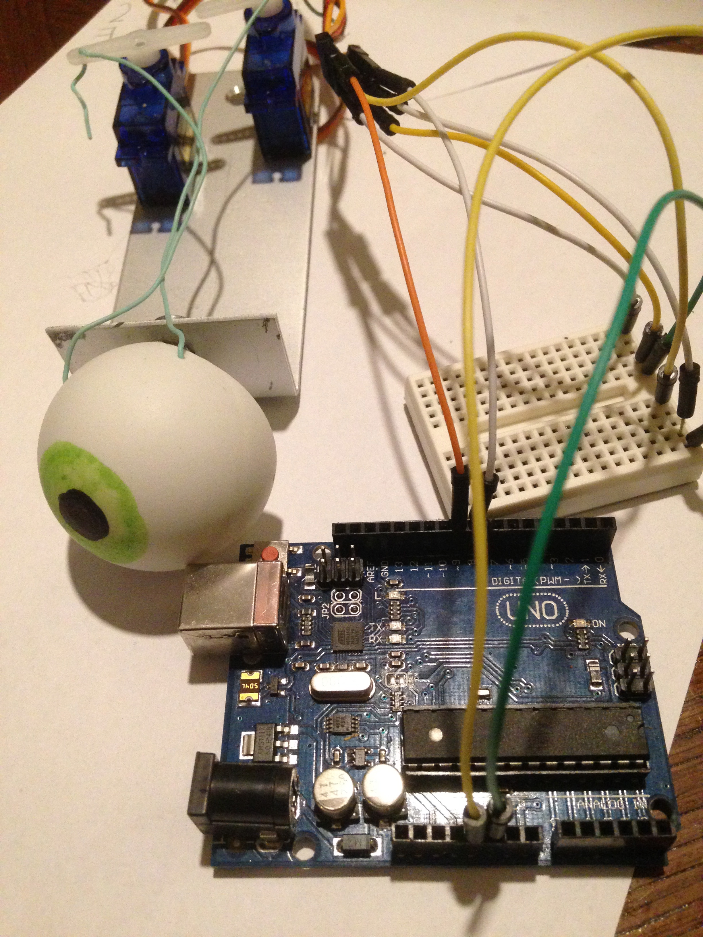
Animatronic Eye
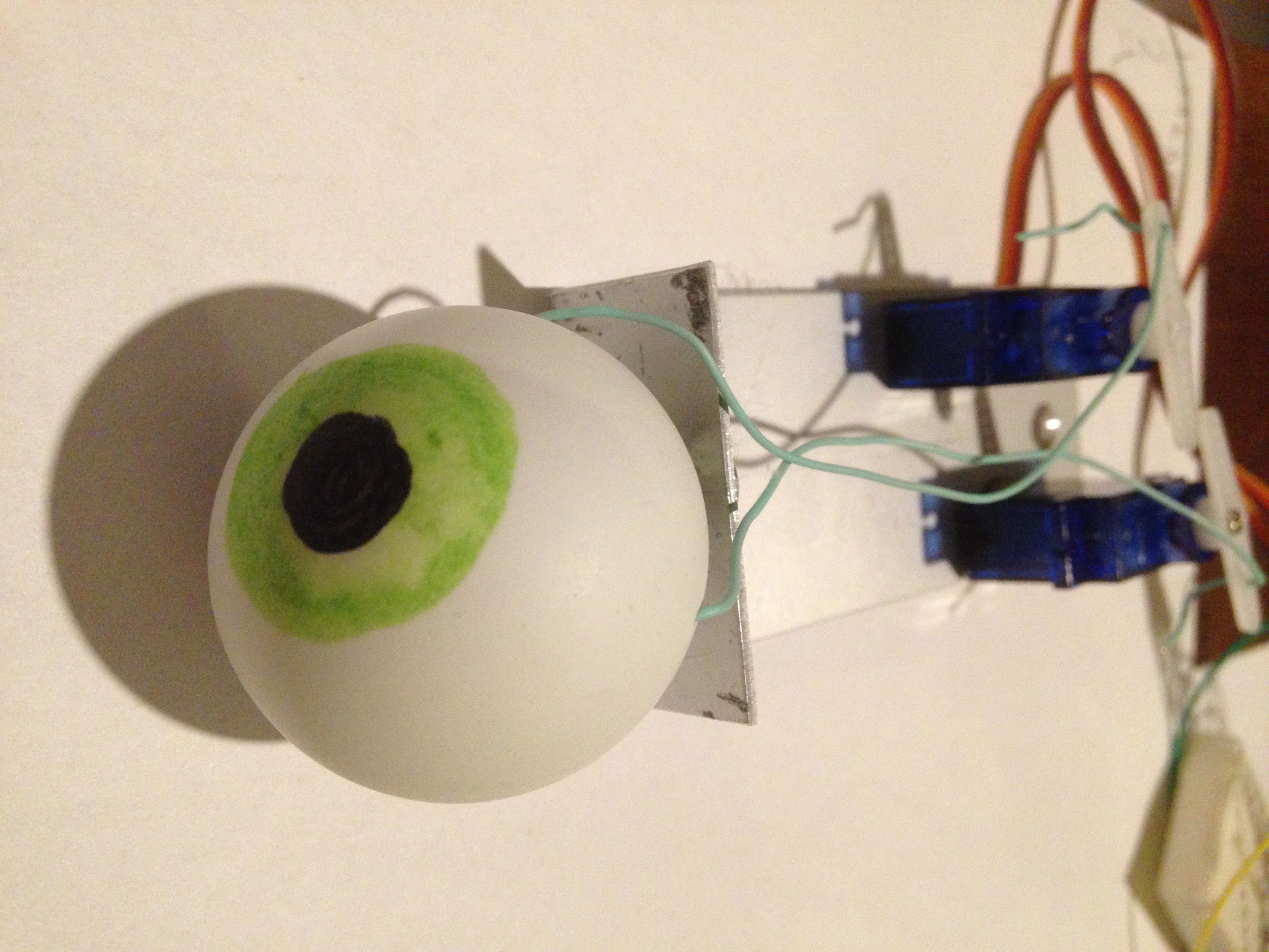
I work as a CNC operator and I think that I have a very cool job but I wanted to prove to myself that I'm able to lead my own projects. I studied control technology at the university but i don't have the opportunity to practice that at work so I decided keep myself going somehow. It was very exciting to discover that technology is so accessible today. I want to build robots in the future and I thought that the eye was a good beginning.
This Is What You Need.
Materials:
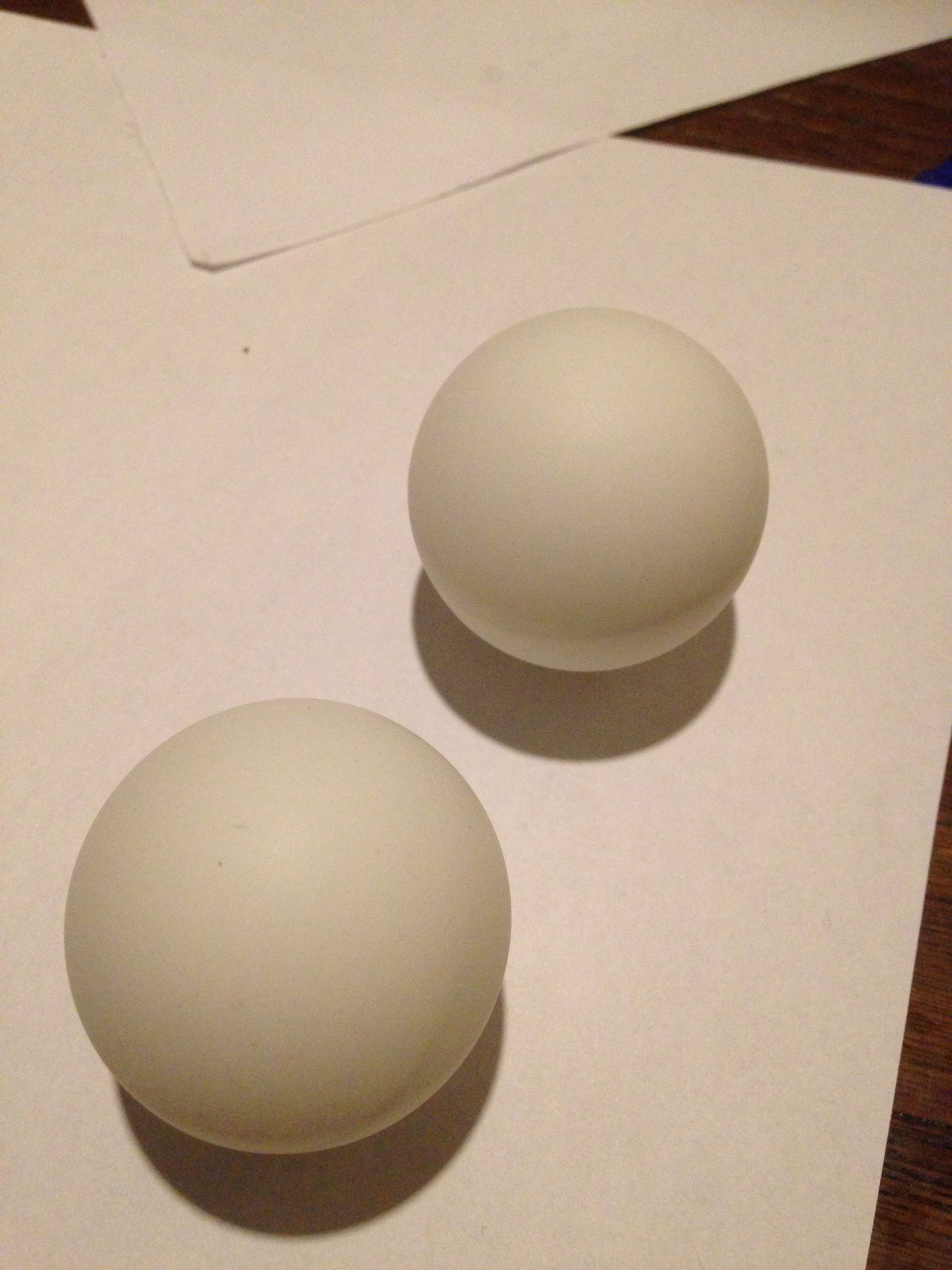
- 2 White ping-pong balls
- Round Head Water Cooling Pipe
Tools:
- Hot glue gun
- round mill
- saw
- Hammer
The Eyes

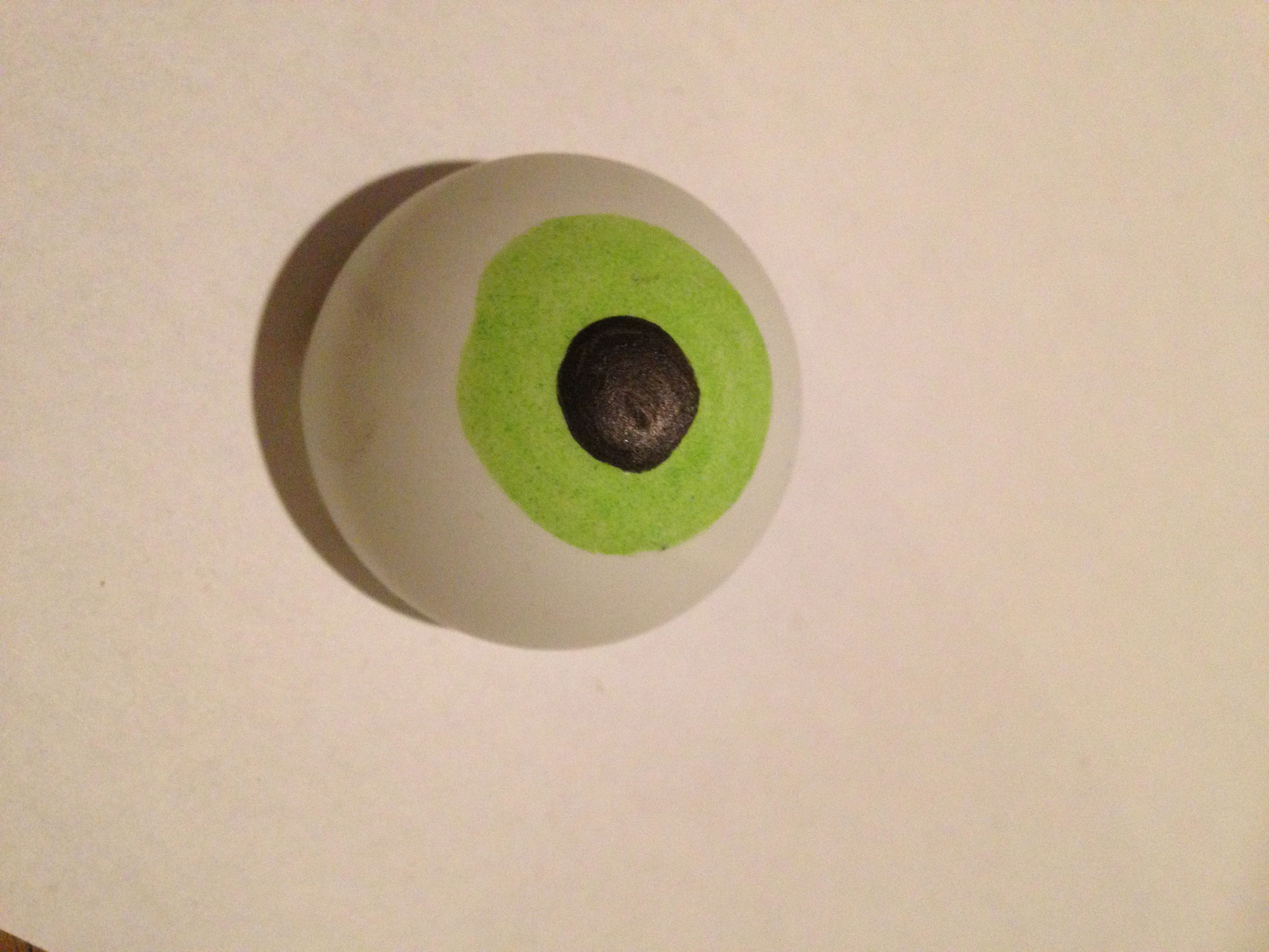
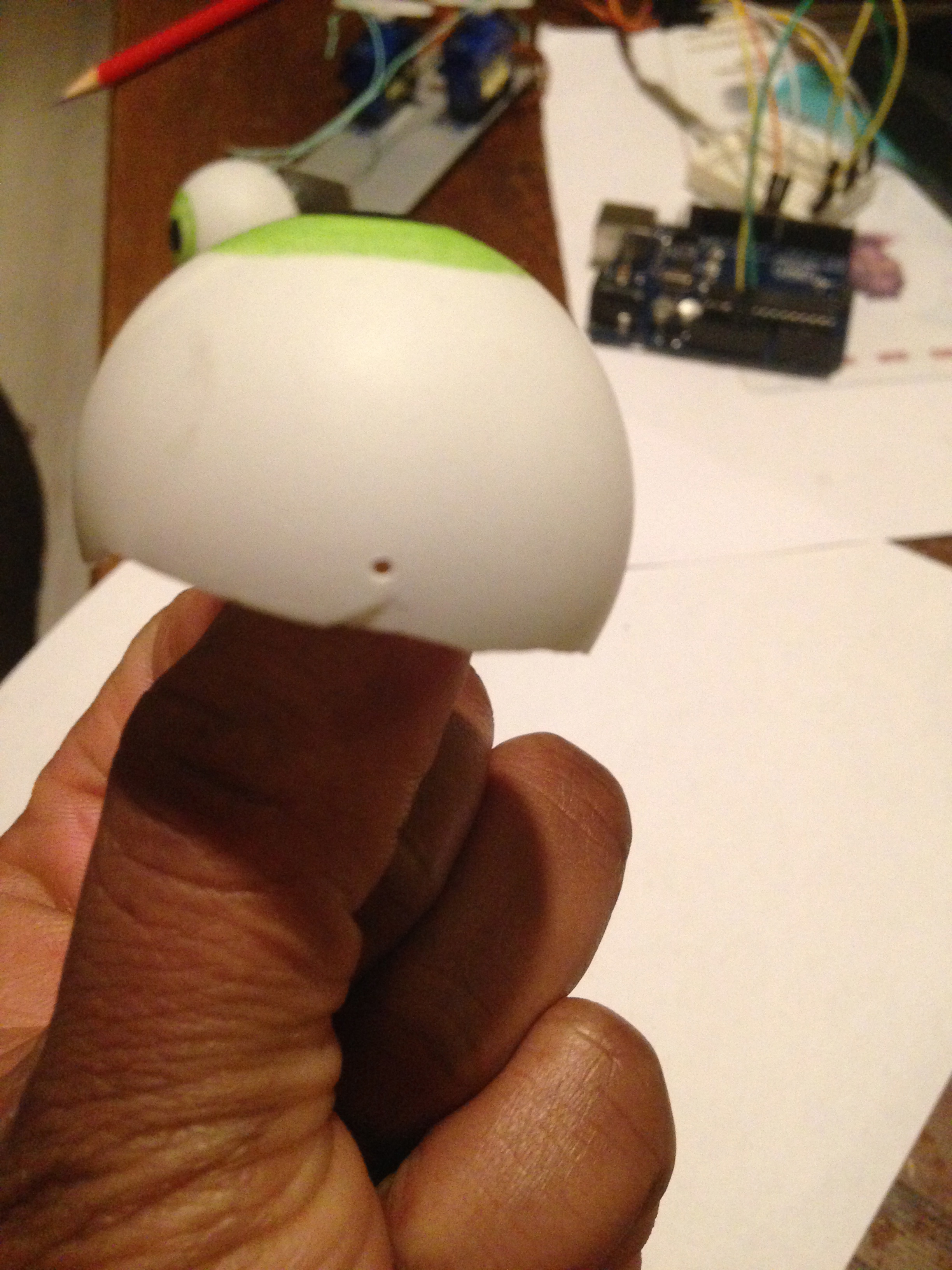
Cut the balls but not in half's. Let one part be much bigger than the other, we cut the balls to be able to put something inside and we need the edges to drills the holes that helps to control the eyes.
Paint and drills the holes.
Fri Rotation.
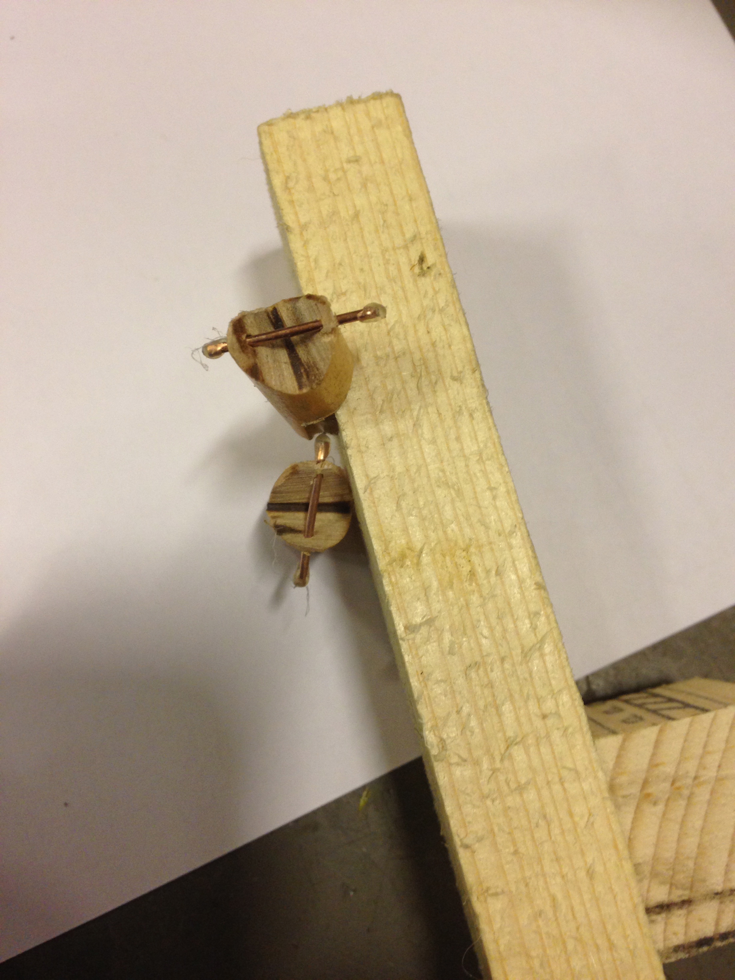
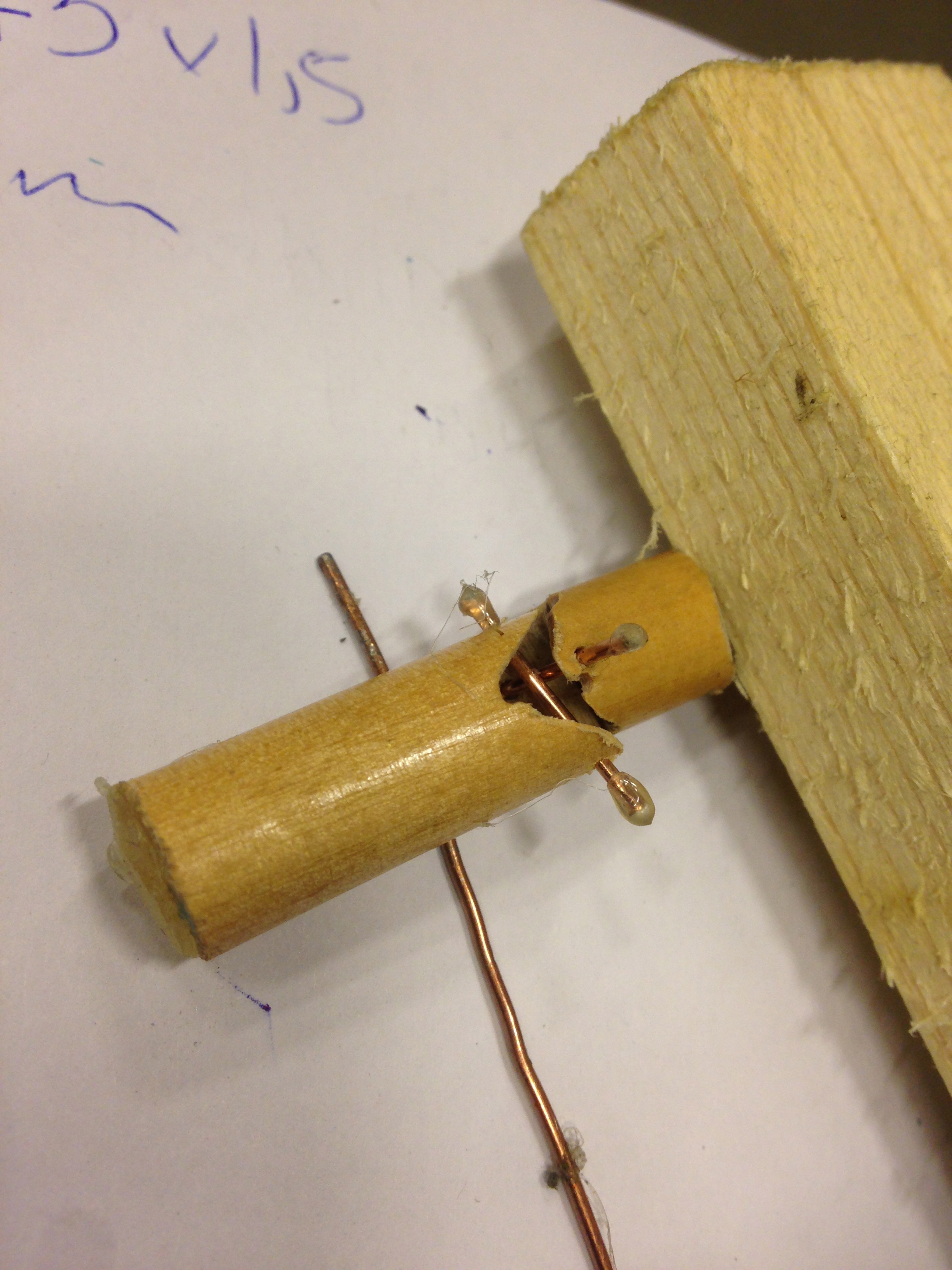
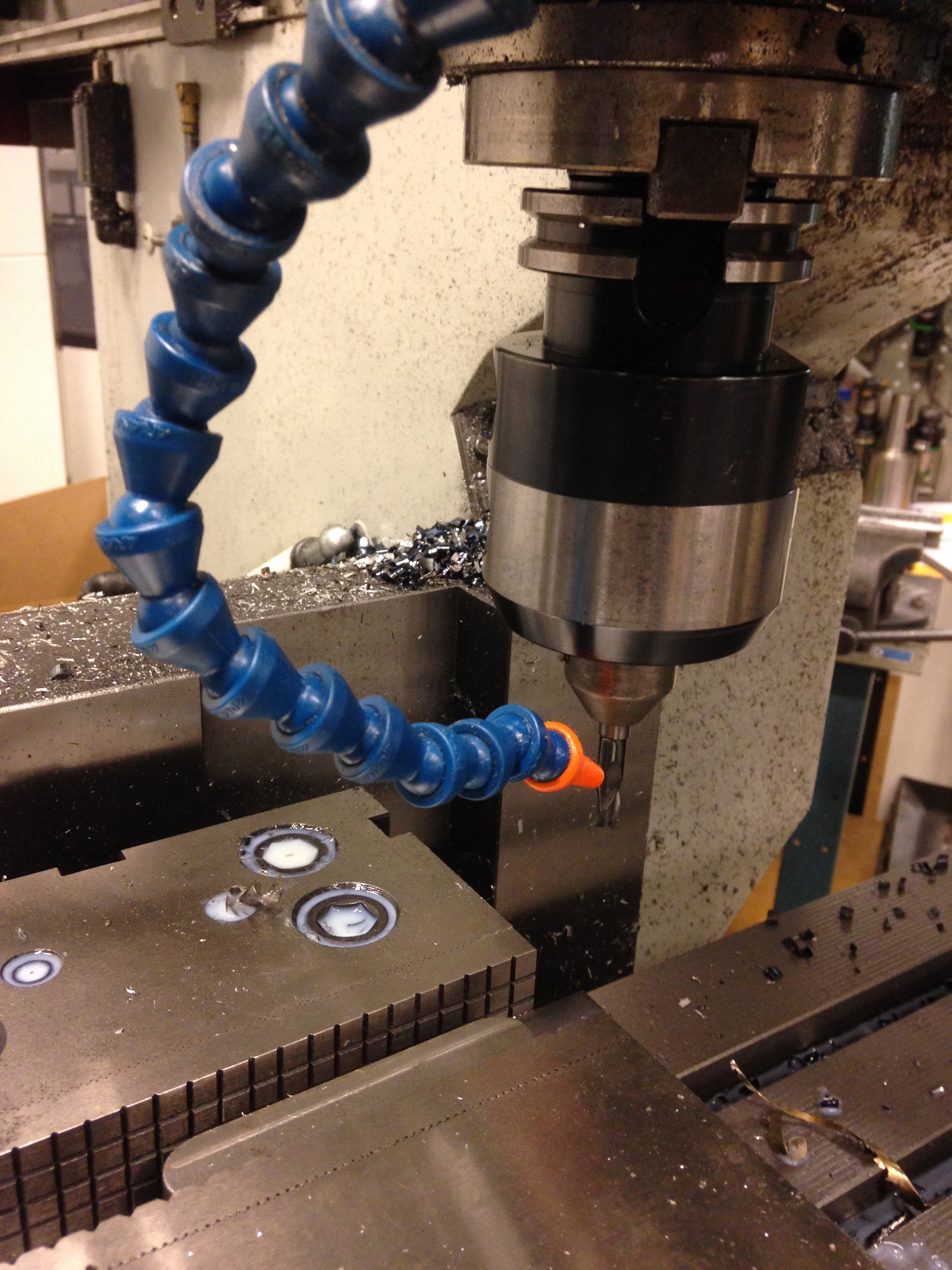
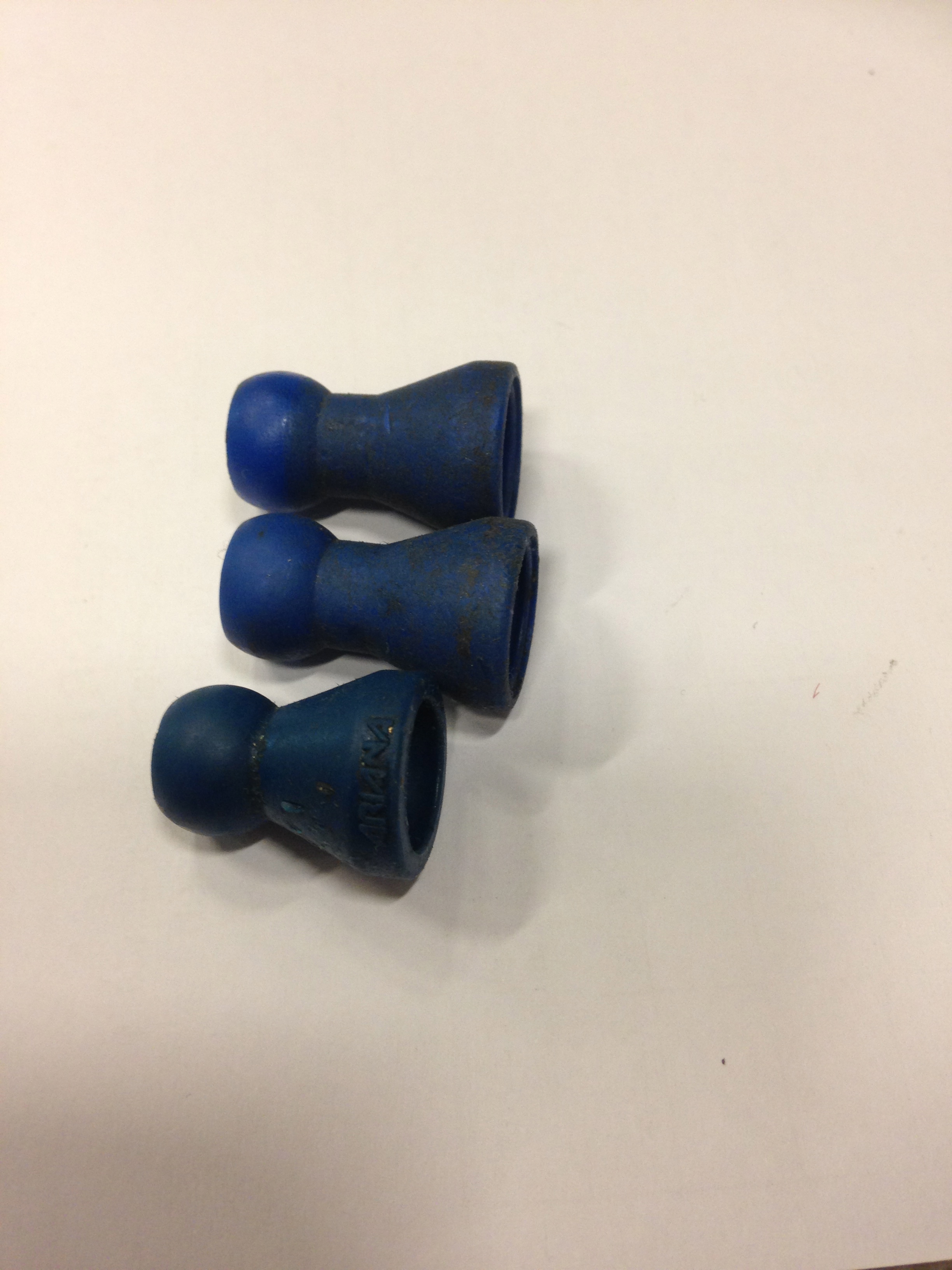
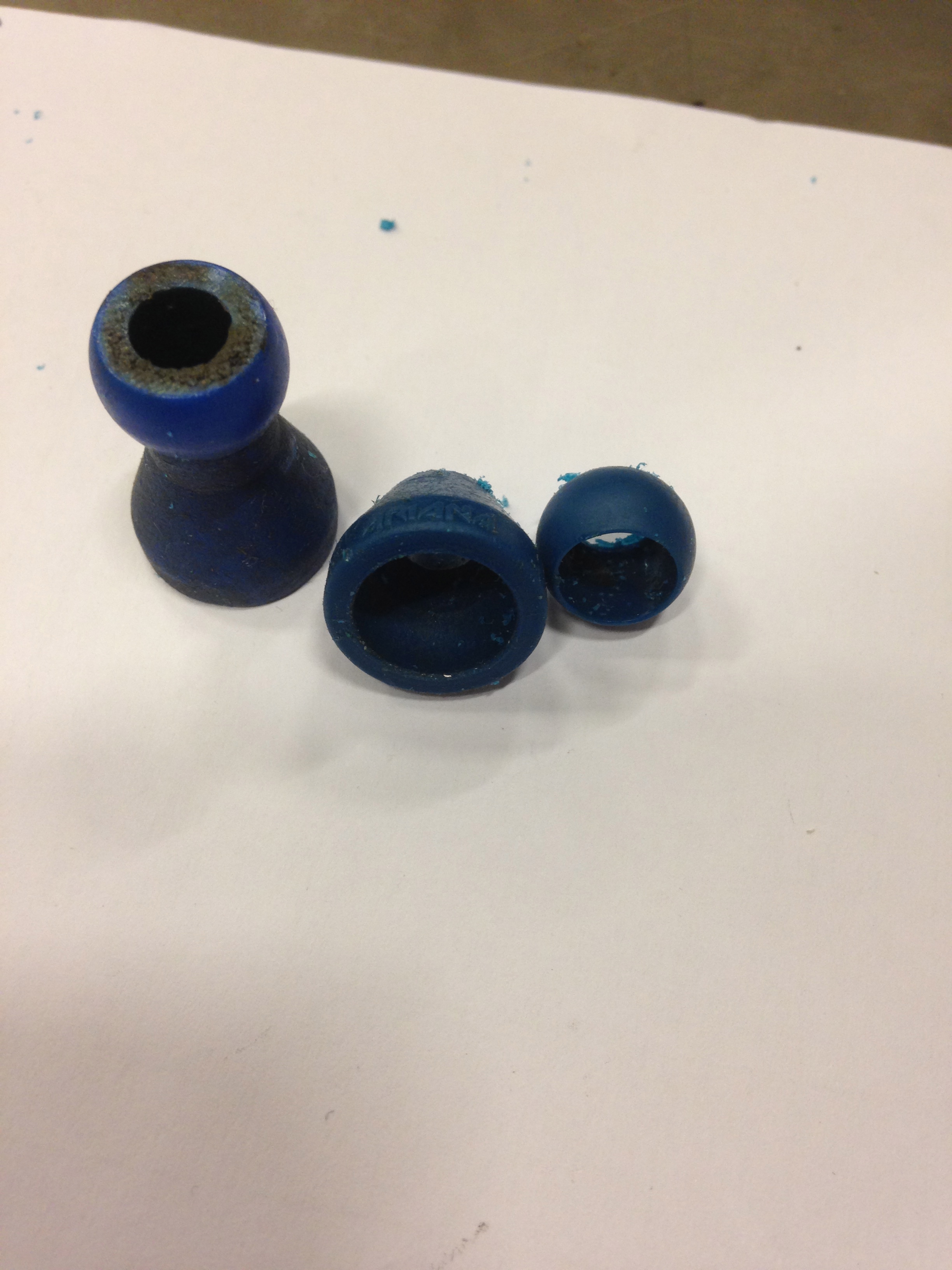
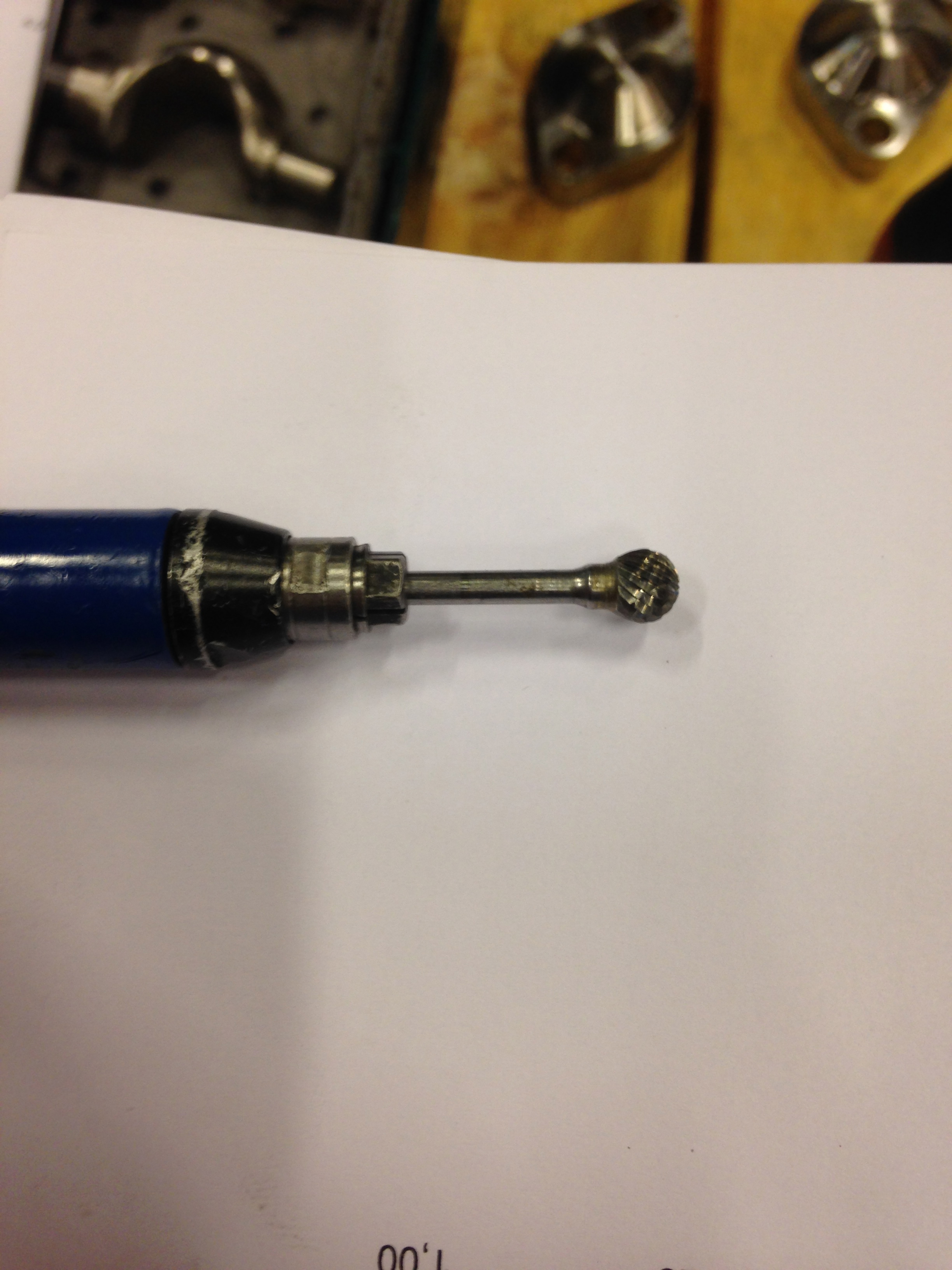

I don't wanted an eye that only moves from one side to another. I saw many instructables but wasn't able to understand how to make it possible. Finally I found a Video on You-Tube but I don't wanted to buy. I made a first attempt using wood and metal from clips. I secured the pins with the glue gun but I wasn't satisfied with the results. As a industrial worker I have access to many things. I observed the the Round Head Water Cooling Pipe looks just like what I needed but it was to tight to rotate free. I milled inside the section and then my part was ready to rotate free.
The Base
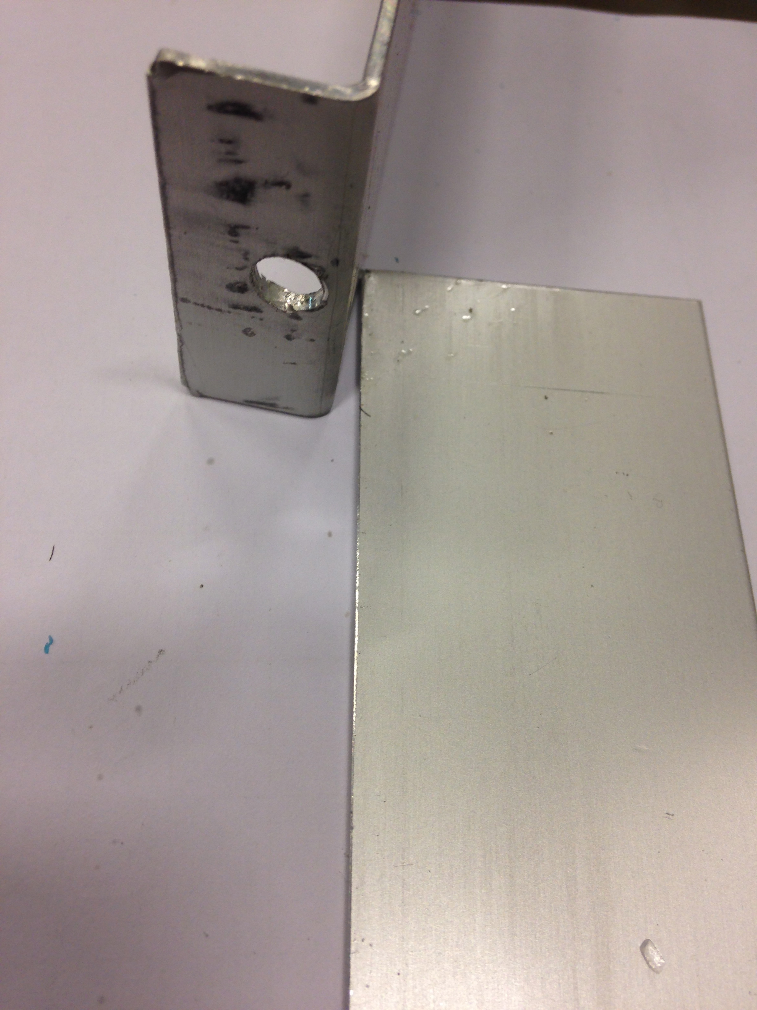
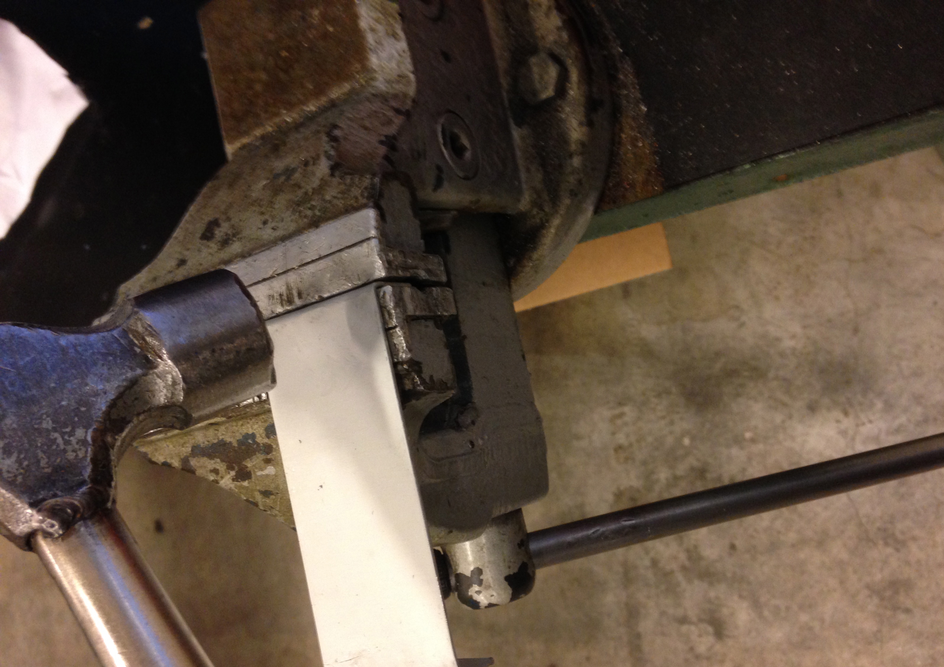
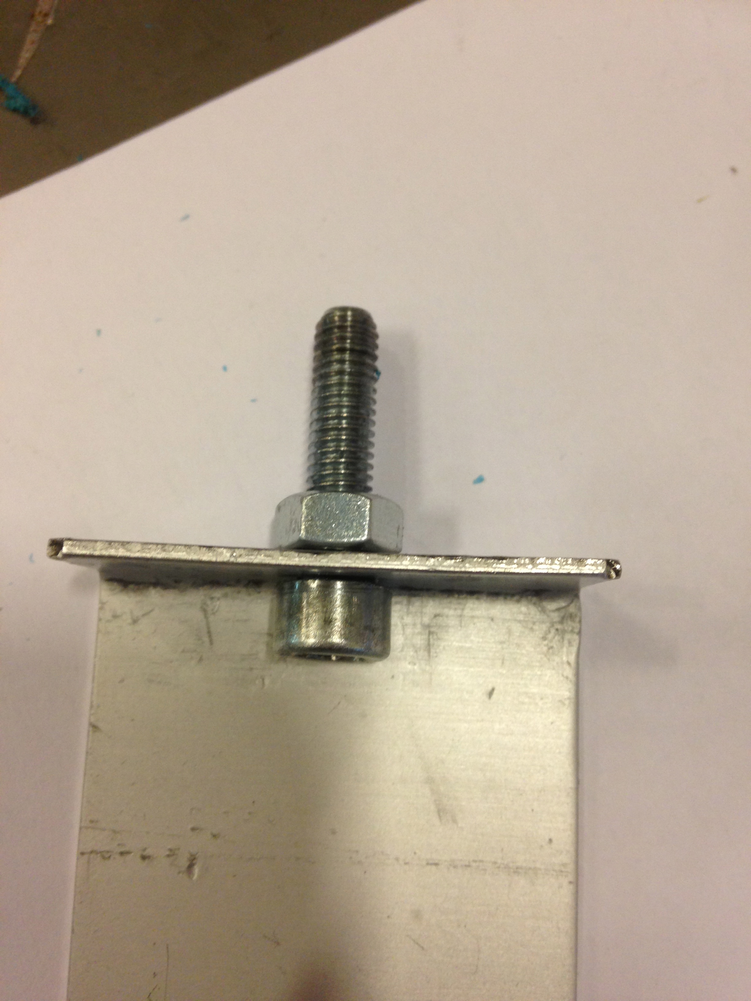
You can use a hammer to bend the base, a bench vise helps to get the perfect 90°. Make sure to drill the hole before bending, it is much easier.
Controlling the Eyes
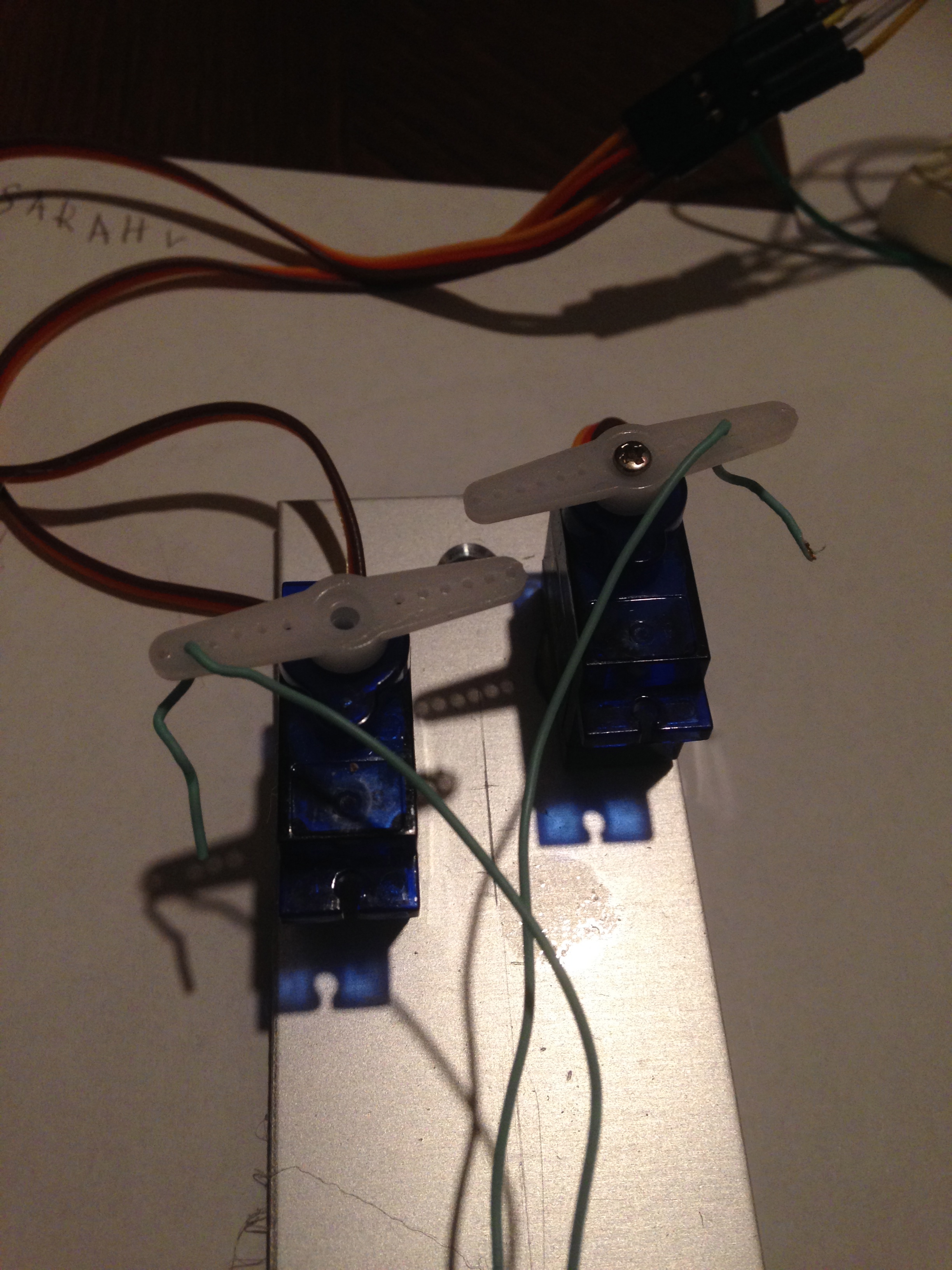
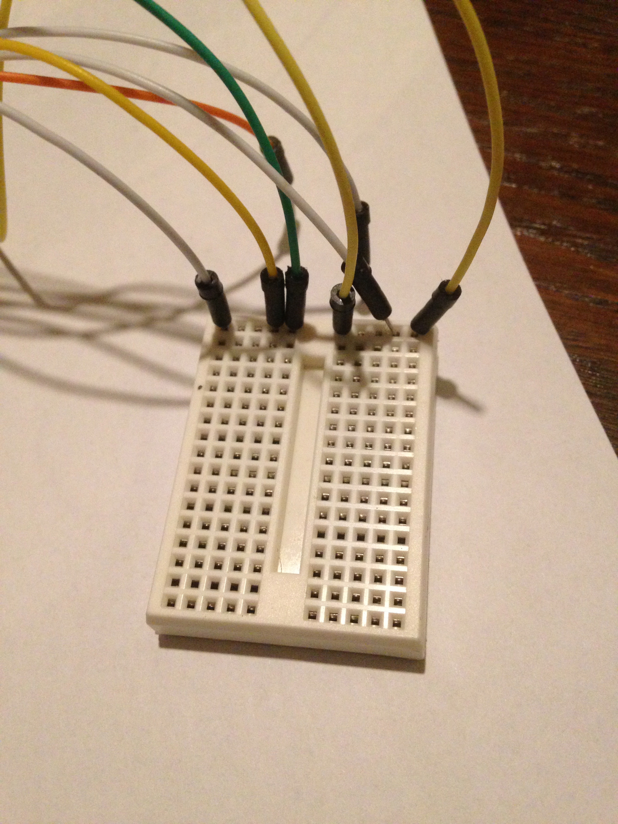
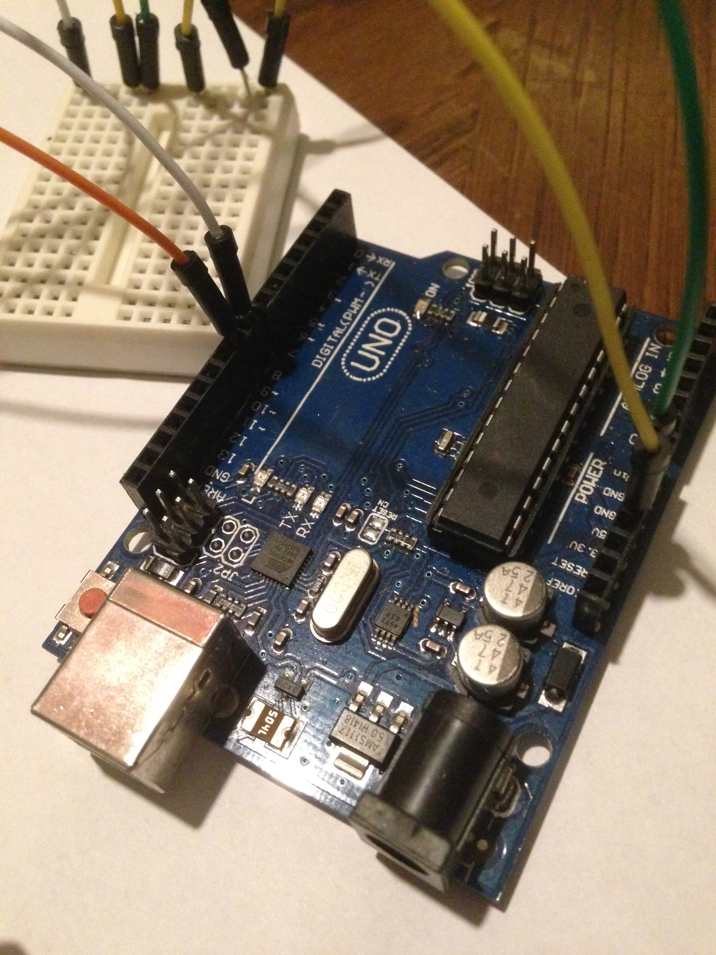
The Program
I'm very new so I needed some help with the program, you can see the project here. My source
Copy and paste the program in your Arduino environment.
#include
#define pi 3.14159265358979323846 #define twopi (2*pi) float circleradius = 50; //50 each side - make no more any of your max limit values float stepnumber = 360; float stepangle;
#include //include servo library for servo control
Servo horServo; //servo for left/right movement Servo vertServo; //servo for up/down movement
byte randomhor; //define random horizontal position variable byte randomvert; //define random vertical position variable int randomdelay; //define random delay variable
#define HLEFTLIMIT 40 //define left limit on horizontal (left/right) servo #define HRIGHTLIMIT 80 //define right limit on horizontal (left/right) servo
#define VTOPLIMIT 70//define top limit on vertical (up/down) servo #define VBOTLIMIT 110 //define bottom limit on horizontal (up/down) servo
void setup() { horServo.attach(8); //horizontal servo on pin 8 vertServo.attach(9); //vertical servo on pin 9 randomSeed(analogRead(0)); //Create some random values using an unconnected analog pin
stepangle = twopi/stepnumber; for(int i = 0; i
x = map(x, 1-circleradius, circleradius, 0, 2*circleradius); y = map(y, 1-circleradius, circleradius, 0, 2*circleradius);
horServo.write(x); //write to the horizontal servo vertServo.write(y); //write to the horizontal servo
delay(10); } }
void loop() { randomhor = random(HLEFTLIMIT, HRIGHTLIMIT); //set limits randomvert = random(VTOPLIMIT, VBOTLIMIT); //set limits randomdelay = random(1000, 4000); //moves every 1 to 4 seconds
horServo.write(randomhor); //write to the horizontal servo vertServo.write(randomvert); //write to the vertical servo delay(randomdelay); //delay a random amount of time (within values set above) }
And Now You Have It!
