Animatronic Orca
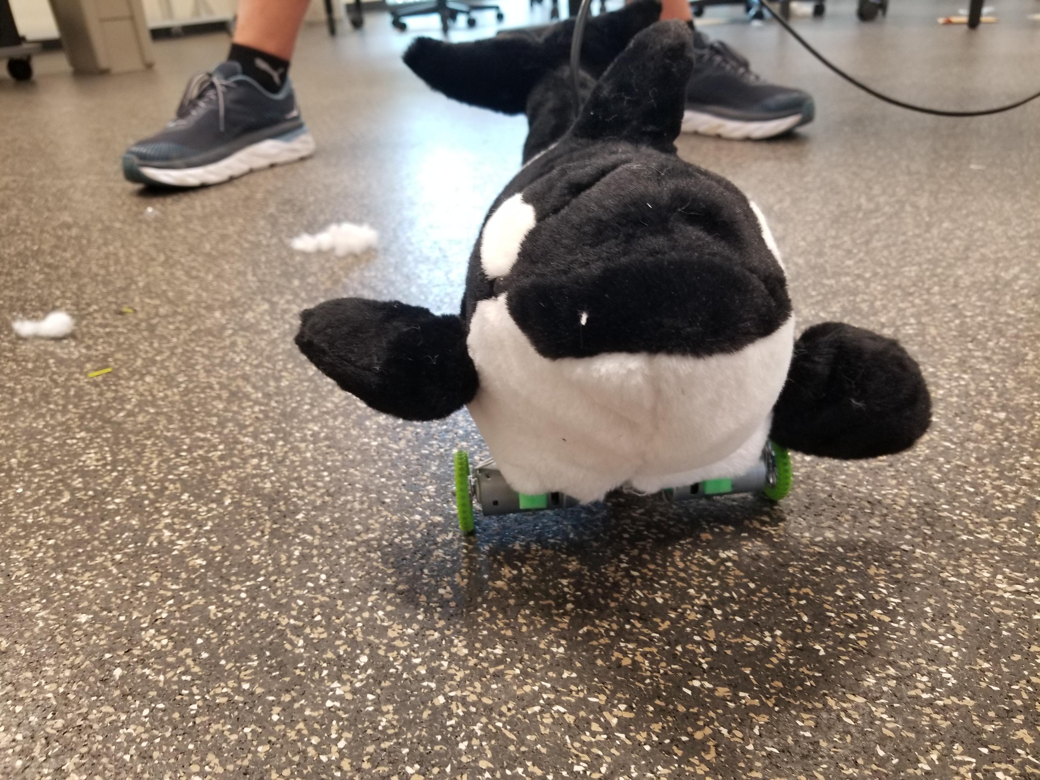
We decided to build a robot that would fit into the plushie of an orca. This animatronic will be able to move its fins, tail, and move around on wheels. The robot is powered by a microcontroller. We decided on the Arduino Nano because of the plentiful pulse width modulated (PWM) output pins and its small size. All of the five motors are controlled using PWM signaling. PWM is a type of signal that changes the duty cycle, or the pulse width of a square wave that comes from the microcontroller. The different duty cycles correspond to different positions that the servo will point to. For the DC motors, the PWM changes the voltage across the motor, which in turn changes how fast the motor turns. The orca is controlled off of a program on a computer to which it is tethered with a USB cable. We used a program called processing to create a user interface and send signals to the microcontroller.
Contributors:
Will LaFreniere
Kenny Bartkiewicz
Alex Wilkinson
Adam Heck
Supplies
These are the basic parts. The cost of all the materials is $100.
1) Orca Plush
https://www.amazon.com/Wild-Republic-Stuffed-Anima...
2) Arduino Nano
https://www.amazon.com/Arduino-A000005-ARDUINO-Nan...
3) 3x Servo Motors
https://www.amazon.com/REC-Micro-Servo-Motor-Proje...
4) DC Motor / Drive Train
https://www.amazon.com/perseids-Chassis-Encoder-Wh...
5) Jumper Wire Set
https://www.amazon.com/gp/product/B00M5WLZDW/ref=p...
6) Armature Wire
https://www.amazon.com/OOK-50143-Gauge-Galvanized-...
7) Mini-B USB Cable
https://www.amazon.com/Hanprmee-Charging-Compatibl...
8) 2x MOSFET IRF3710Z
https://www.mouser.com/ProductDetail/Infineon-IR/I...
9) 2x 220 Ohm Resistor
https://www.mouser.com/ProductDetail/Yageo/KNP500J...
10) 2x 1N4004 Diode
https://www.mouser.com/ProductDetail/ON-Semiconduc...
11) Small Breadboard
Programming the Microcontroller
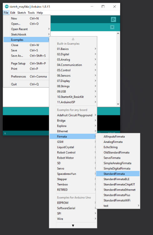
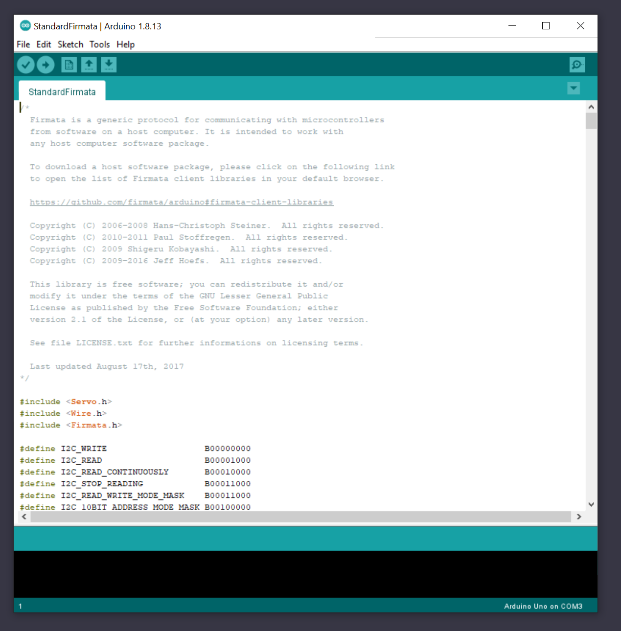


- Open the Arduino IDE and upload the StandardFirmata code from the examples. This will allow the processing code and our GUI to interact with the microcontroller
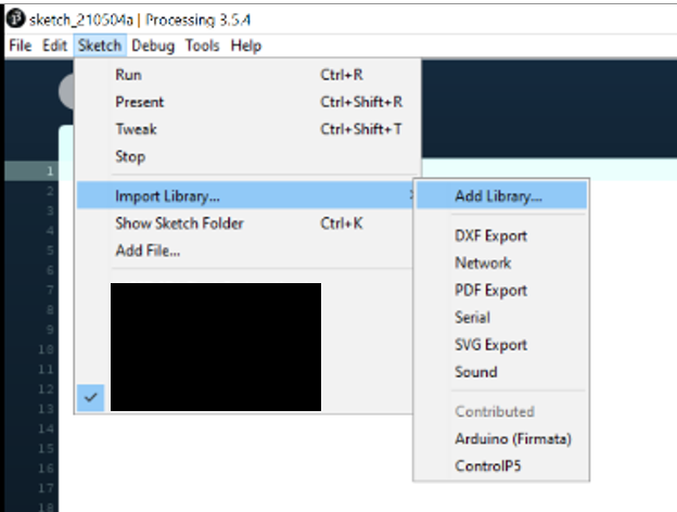
- Inside the Processing, IDE add the libraries "Arduino (Firmata)" and "ControlP5"
- Once you have added the libraries to the IDE, copy and paste the code in the next section to Processing.
- Pressing the play button will run the program - the GUI will not properly load if the Arduino with the Standard Firmata code is not plugged into the computer
If you are having trouble with the software, here are some guides that may help:
https://www.arduino.cc/en/guide/windows
https://learn.sparkfun.com/tutorials/connecting-ar...
The Code
import processing.serial.*;
import cc.arduino.*;
import controlP5.*;
ControlP5 cp5;

Arduino arduino;

//INITIALIZE THE VARIABLES
float squarePos;
int potVal;

int Speed = 0;
int Key_On_U = 0;
int Key_On_L = 0;
int Key_On_R = 0;
int Flipper_Angle_R = 0;
int Flipper_Angle_L = 0;
int Tail_Angle = 0;

void setup() {
  size(400, 400);
  printArray(Arduino.list());
  arduino = new Arduino(this, Arduino.list()[0], 57600); //CONNECT TO THE ARDUINO

  //SETUP THE PINS ON THE ARDUINO
  arduino.pinMode(3, Arduino.OUTPUT); //Left Drive
  arduino.pinMode(11, Arduino.OUTPUT); //Right Drive
  arduino.pinMode(5, Arduino.SERVO); //Right Fin
  arduino.pinMode(6, Arduino.SERVO); //Left Fin
  arduino.pinMode(9, Arduino.SERVO); //Tail

  //CREATE THE SPEED SLIDER
  cp5 = new ControlP5(this);
  cp5.addSlider("Speed")
  .setPosition(10,50)
  .setRange(100, 255)
  .setSize(300,20);

  //CREATE THE RIGHT FLIPPER SLIDER
   cp5.addSlider("Flipper_Angle_R")
  .setPosition(10,90)
  .setRange(0,100)
  .setSize(300,20);

  //CREATE THE LEFT FLIPPER SLIDER
   cp5.addSlider("Flipper_Angle_L")
  .setPosition(10,130)
  .setRange(0, 100)
  .setSize(300,20);

  //CREATE THE TAIL ANGLE SLIDER
  cp5.addSlider("Tail_Angle")
  .setPosition(10,170)
  .setRange(0, 50)
  .setSize(300,20);

}

void draw() {
  background(255);
  fill(0);

  textSize(14); //LABEL FOR SPEED SLIDER
  text("Speed", 20, 45);
  fill(0);

  textSize(14); //LABEL FOR RIGHT FLIPPER SLIDER
  text("Right Flipper Angle", 20, 85);
  fill(0);

  textSize(14); //LABEL FOR LEFT FLIPPER SLIDER
  text("Left Flipper Angle", 20, 125);
  fill(0);

  textSize(14); //LABEL FOR TAIL ANGLE SLIDER
  text("Tail Angle", 20, 165);
  fill(0);

  textSize(14); //TELLING YOU HOW TO MOVE THE ORCA
  text("Use Directional Keys For Movement", 85, 330);
  fill(0);

  beginShape(); //CREATE TRIANGLE 1
  stroke(3);
  fill(0,0,Key_On_U);
  triangle(200, 230, 220, 270, 180, 270);
  endShape();

  beginShape(); //CREATE TRIANGLE 2
  stroke(3);
  fill(0,0,Key_On_R);
  triangle(260, 290, 220, 270, 220, 310);
  endShape();

  beginShape(); //CREATE TRIANGLE 3
  stroke(3);
  fill(0,0,Key_On_L);
  triangle(140, 290, 180, 270, 180, 310);
  endShape();

  //Change the duty cycle of the output to the servos
  arduino.servoWrite(5, Flipper_Angle_R);
  arduino.servoWrite(6, Flipper_Angle_L);
  arduino.servoWrite(9, Tail_Angle);


}

//READS THE KEY PRESSES FROM THE KEBOARD
void keyPressed() {
  if (key == CODED) {
    if (keyCode == UP) {			//IF UP KEY PRESSED
      arduino.analogWrite(3, Speed); 		//SET RIGHT MOTOR TO SPEED
      arduino.analogWrite(11, Speed); 		//SET RIGHT MOTOR TO SPEED
      Key_On_U = 255; 				//SET UP TRIANGLE COLOR TO WHITE
    }
    else if (keyCode == RIGHT) { 		//IF LEFT KEY PRESSED
      arduino.analogWrite(3, Speed);		//SET RIGHT MOTOR TO SPEED
      arduino.analogWrite(11, Arduino.LOW);	//TURN LEFT MOTOR OFF
      Key_On_L = 255;				//SET LEFT TRIANLGE COLOR TO WHITE
    }
    else if (keyCode == LEFT) {  		//IF RIGHT KEY PRESSED
      arduino.analogWrite(3, Arduino.LOW);	//TURN RIGHT MOTOR OFF
      arduino.analogWrite(11, Speed);		//SET LEFT MOTOR TO SPEED
      Key_On_R = 255;				//SET RIGHT TRIANGLE COLOR TO WHITE
    }
  }
}

//READS THE KEY RELEASES FROM THE KEYBOARD
void keyReleased() {
  if (key == CODED) {
    if (keyCode == UP) {			//IF UP KEY RELEASED
      arduino.analogWrite(3, Arduino.LOW);	//TURN OFF BOTH MOTORS
      arduino.analogWrite(11, Arduino.LOW);
      Key_On_U = 0;				//SET UP TRIANGLE COLOR TO BLACK
    }
    else if (keyCode == LEFT) {			//IF LEFT KEY RELEASED
      arduino.analogWrite(3, Arduino.LOW);	//TURN BOTH MOTORS OFF
      arduino.analogWrite(11, Arduino.LOW);
      Key_On_L = 0;				//SET LEFT TRIANGLE COLOR TO BLACK
    }
    else if (keyCode == RIGHT) {		//IF RIGHT KEY RELEASED
      arduino.analogWrite(3, Arduino.LOW);	//TURN BOTH MOTORS OFF
      arduino.analogWrite(11, Arduino.LOW);
      Key_On_R = 0;				//TURN RIGHT TRIANGLE COLOR TO BLACK
    }
  }
}
Downloads
Circuit Construction
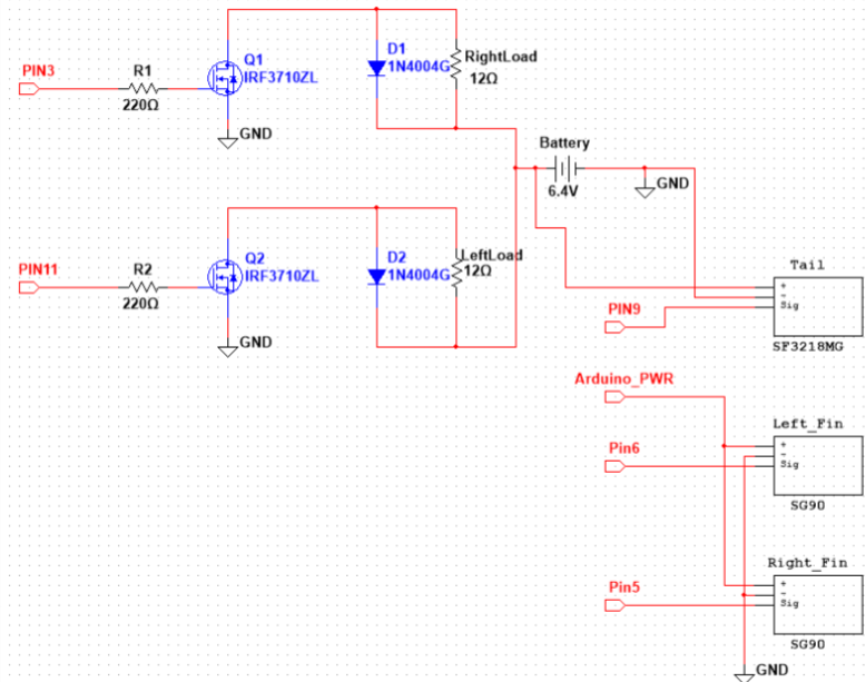
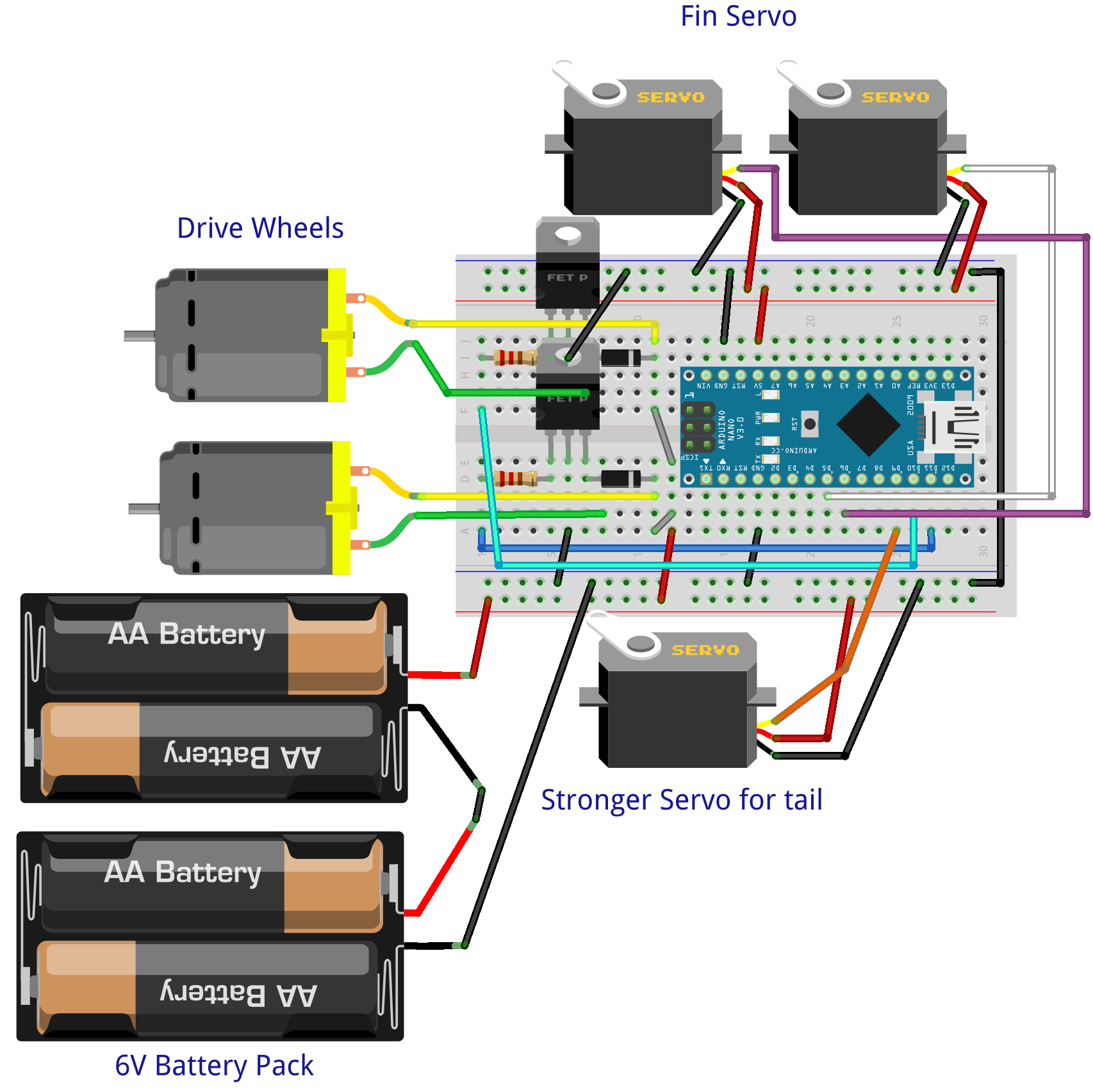
- Connect both ground busses on the breadboard together with a jumper
- Plug the Arduino nano into the breadboard, bridging the gap in the middle
- Connect the GND pin from the Arduino to the upper ground rail on the breadboard
- Connect the 5V pin to the upper power rail on the breadboard
- Connect the ground lead from each of the servos to the upper ground bus
- Connect the power lead from each of the servos to the upper power bus
- Connect the signal lead from the servos to pins to pins 5, 6, and 9
- Pin 5 is for the right fin servo
- Pin 6 is for the left fin servo
- Pin 9 is for the tail servo
- Place both MOSFETS on the breadboard
- Connect the gate of one MOSFET to pin 3 on the microcontroller and connect the gate of the other microcontroller to pin 11 on the microcontroller. Make sure that the 220 Ohm resistor is between the gate and the microcontroller
- Connect the source pin on both microcontrollers to the ground bus
- Plug both diodes into the breadboard
- Using jumpers, connect the positive end of the diodes to the lower power bus of the breadboard and the negative end of the diode to the drain of one of the most
If you are unfamiliar with how a breadboard works, here is a link that explains how all the holes connect.
https://learn.sparkfun.com/tutorials/how-to-use-a-...
When we connect to put the breadboard into the frame, we will connect the motor and battery leads. Instructions on doing so will be in that step.
If you plug in the microcontroller to your computer and run the program, you should be able to test if the servos are working properly.
Orca Skeleton Construction
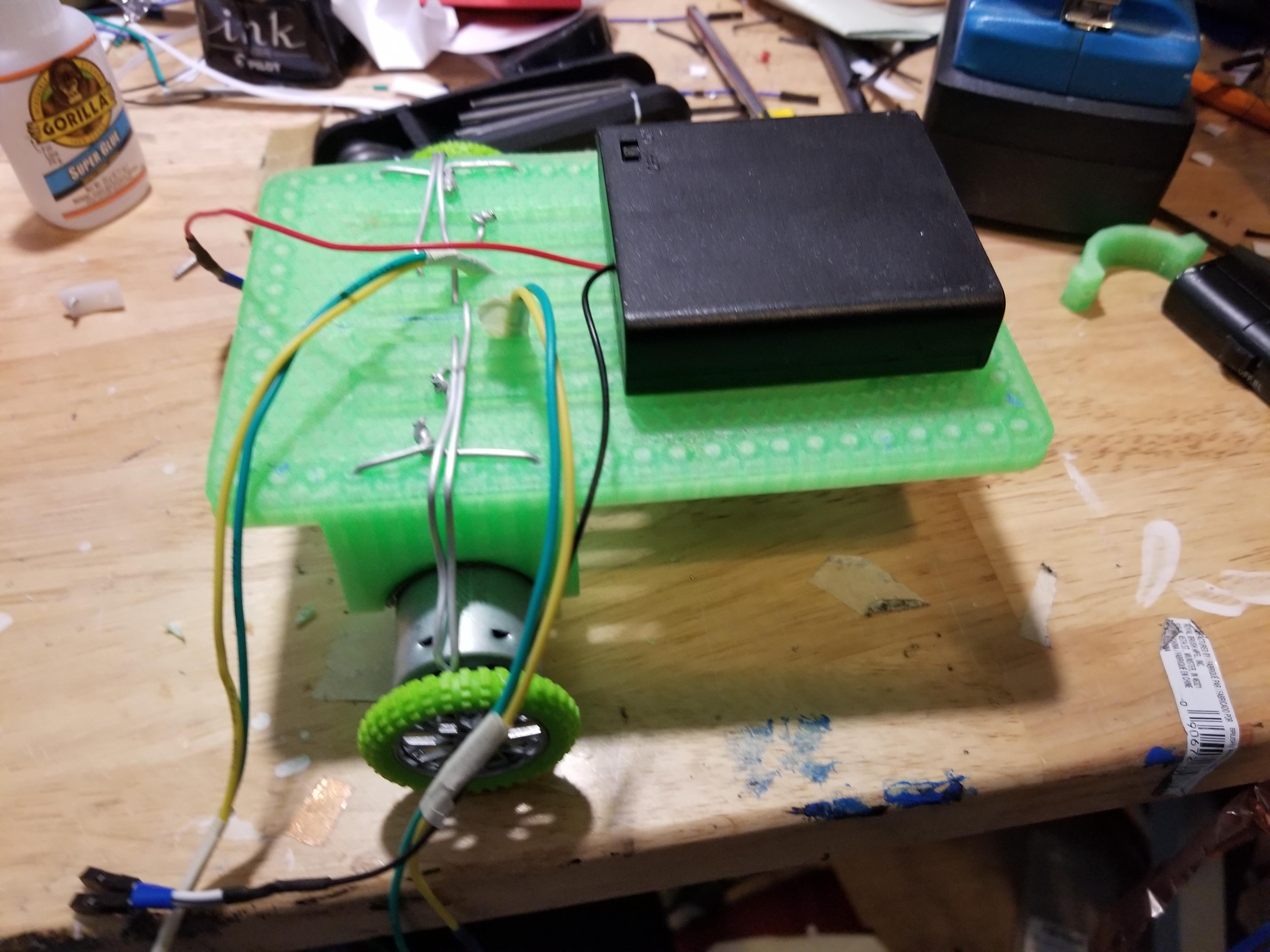
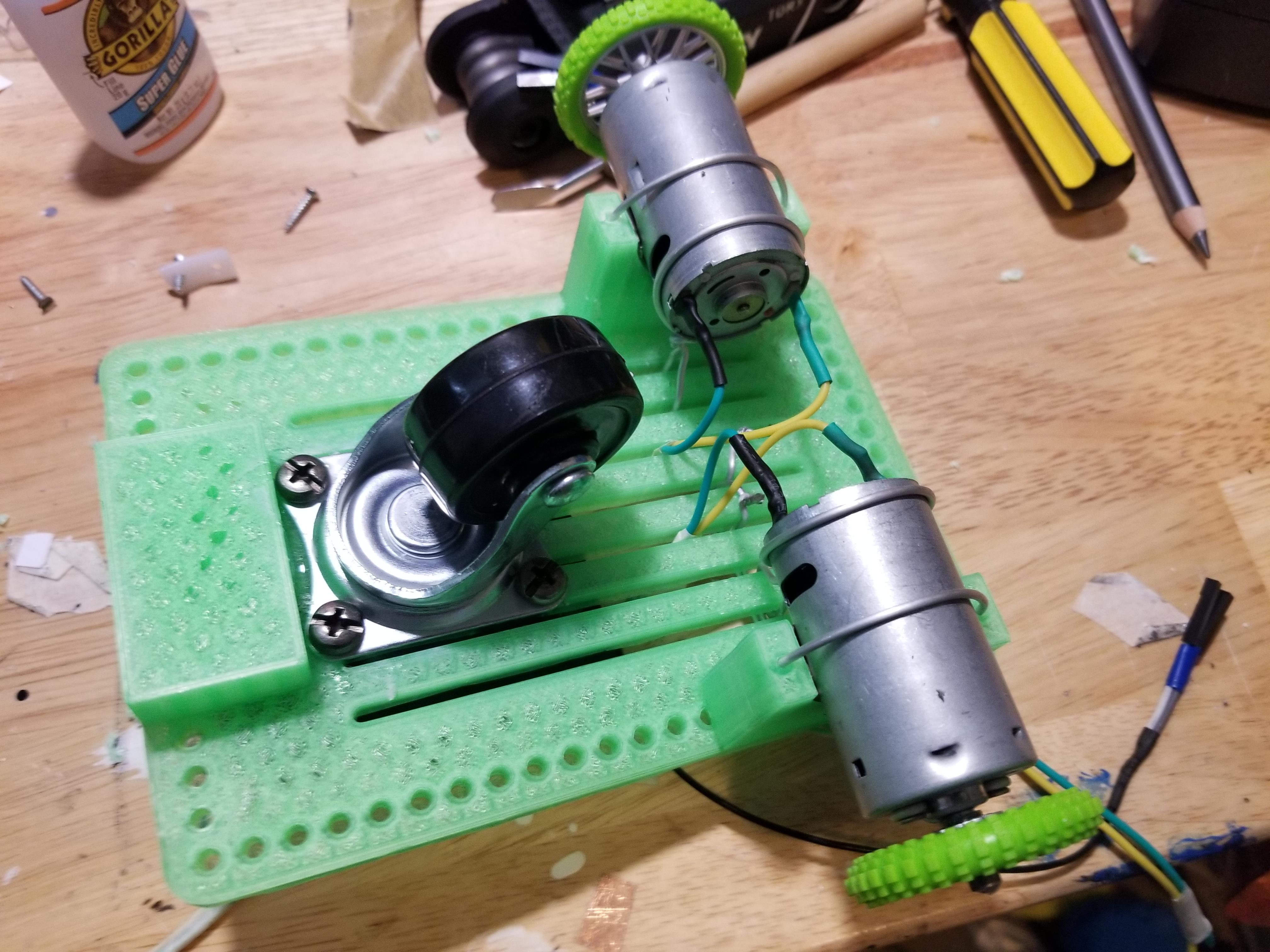
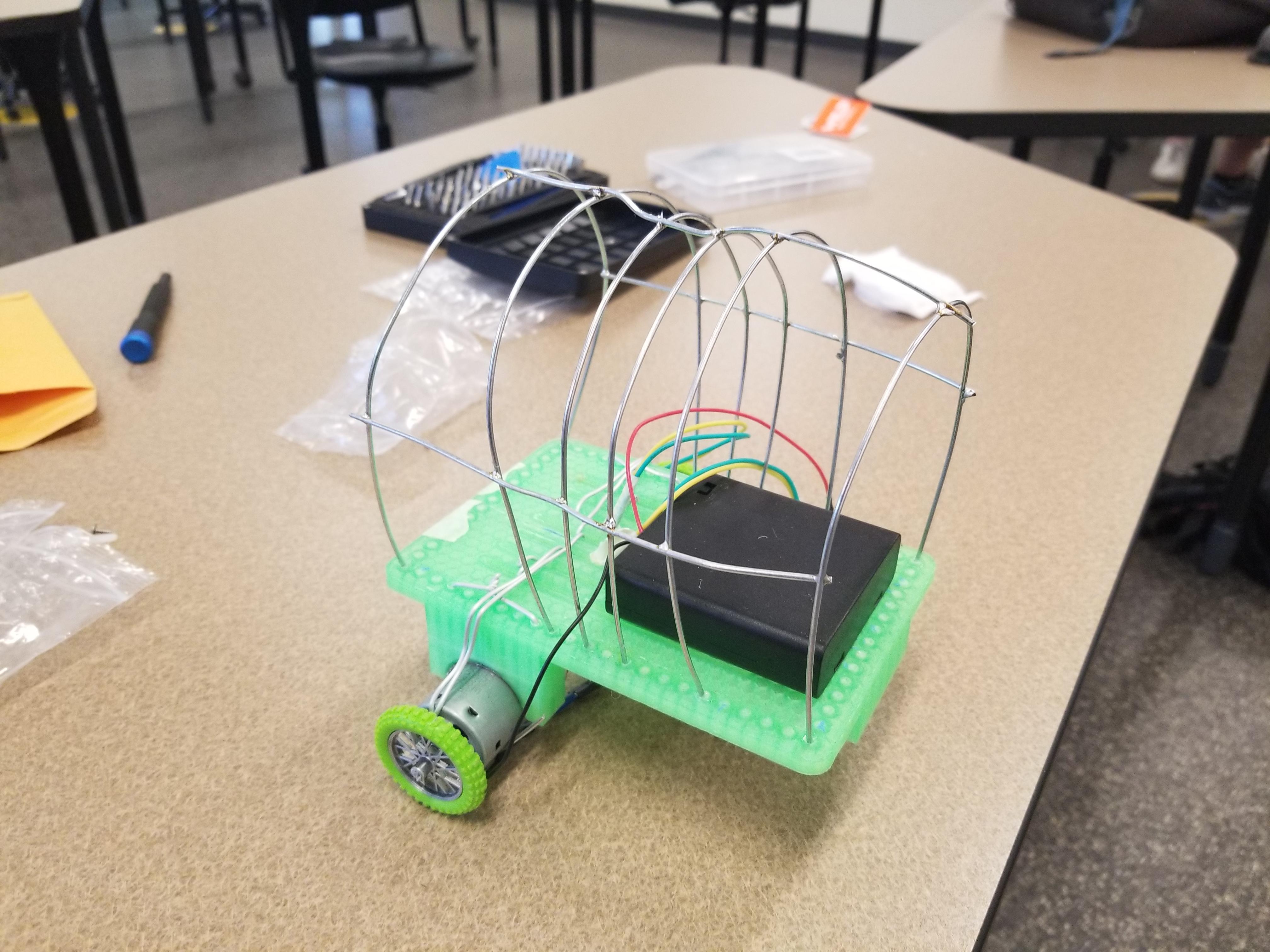
- The first part of the construction is to assemble the drive train. Follow the instructions that are included to build it. Our photos use different parts because of complications with shipping, but the drive train in the parts list will operate the same way.
- The basic frame is easy to construct and the exact measurements are unimportant. The main goal is to hold the plushie up in the basic shape that it had before the stuffing was removed.
- Create arches that follow the shape of the orca - around six that are evenly spaced across the drive train surface
- Bed the armature wire to follow the rough shape of the body
- Cut the wire to the appropriate size
- Superglue the arches to the drive train
- Once all the vertical arches are standing upright, connect them with horizontal strips of armature wire
- We used solder to join the lengths of wire, but you could twist them with pliers as well.
- One length on each side and one across the top should be sufficient to keep it sturdy
- Create "U"'s of armature wire that will hold the fin servos
Orca Body Tailoring
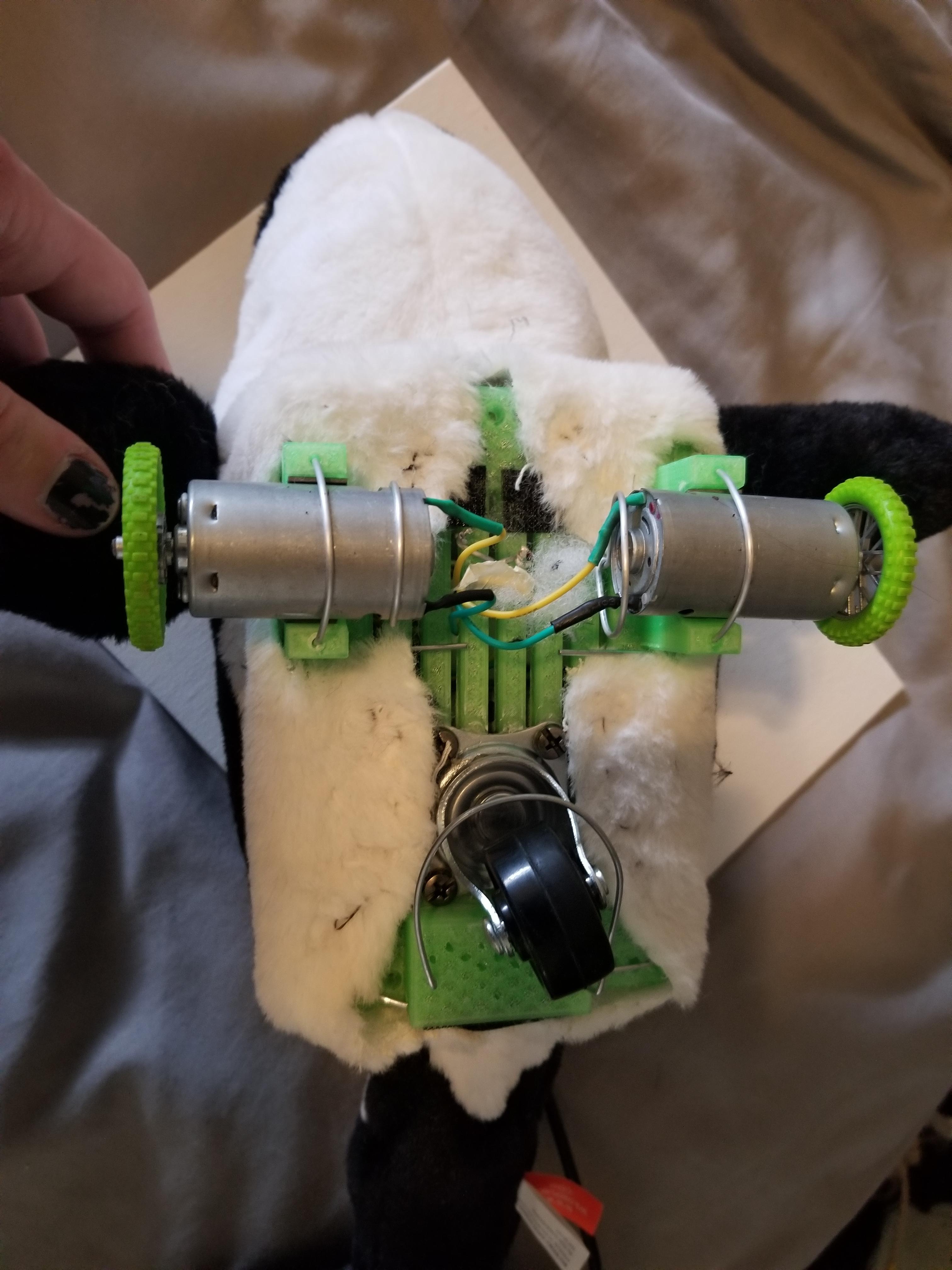
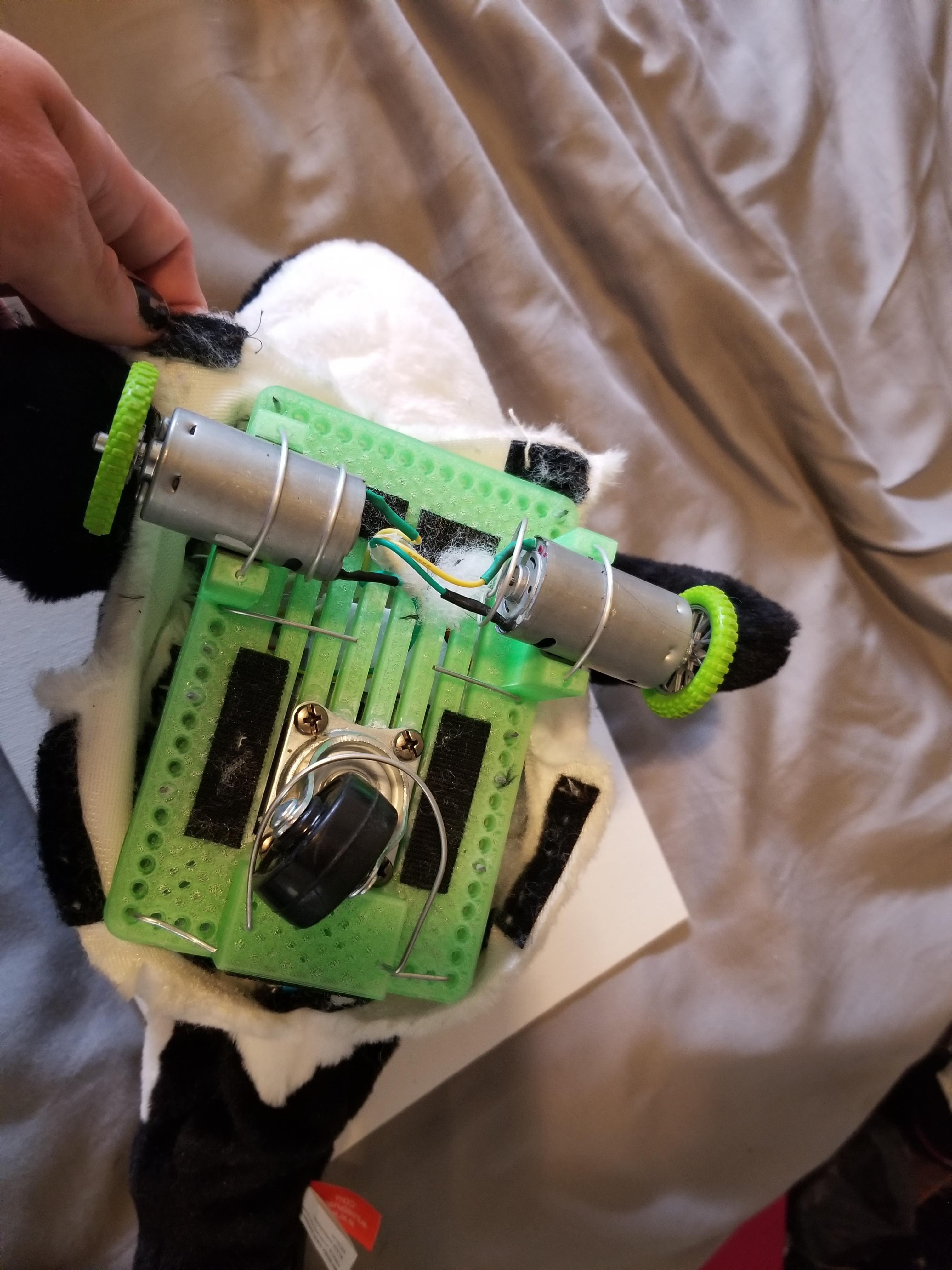
- Cut open whale along the middle bottom seam in the large part of the body
- Cut to about an inch or two further than the length of the chassis
- Cut about a 1"x.75" strip out of either side of the cut belly to allow for wheel clearance, measure against the frame to find a position
- Attach rough side of Velcro to the underside of chassis in positions as shown/to allow proper seating of skin
- Sew soft side of Velcro to the skin in positions corresponding to a rough side on the bottom of the chassis
- Cut a hole in the back of the orca to feed the USB cable through
Circuit and Skeleton Integration
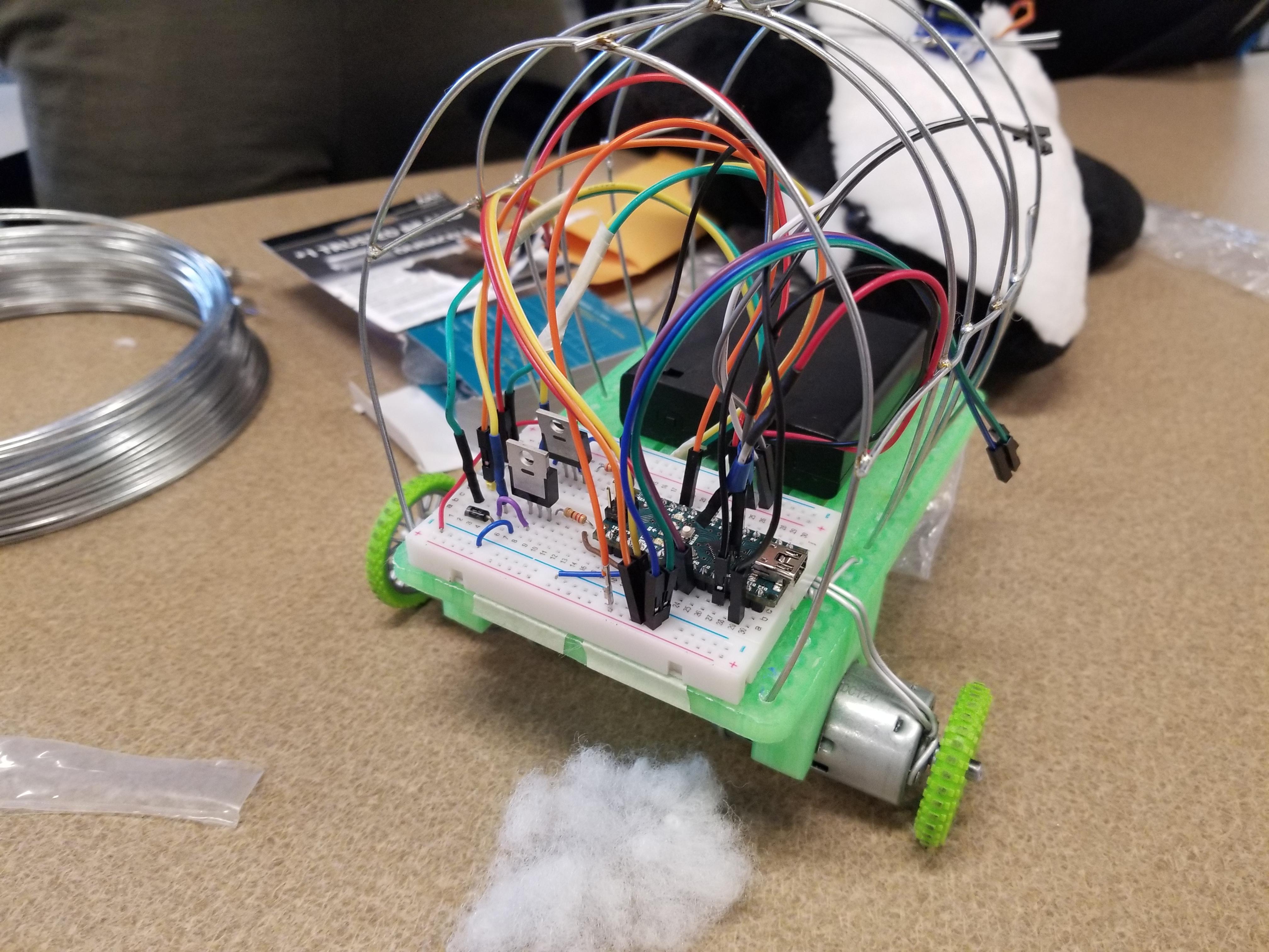
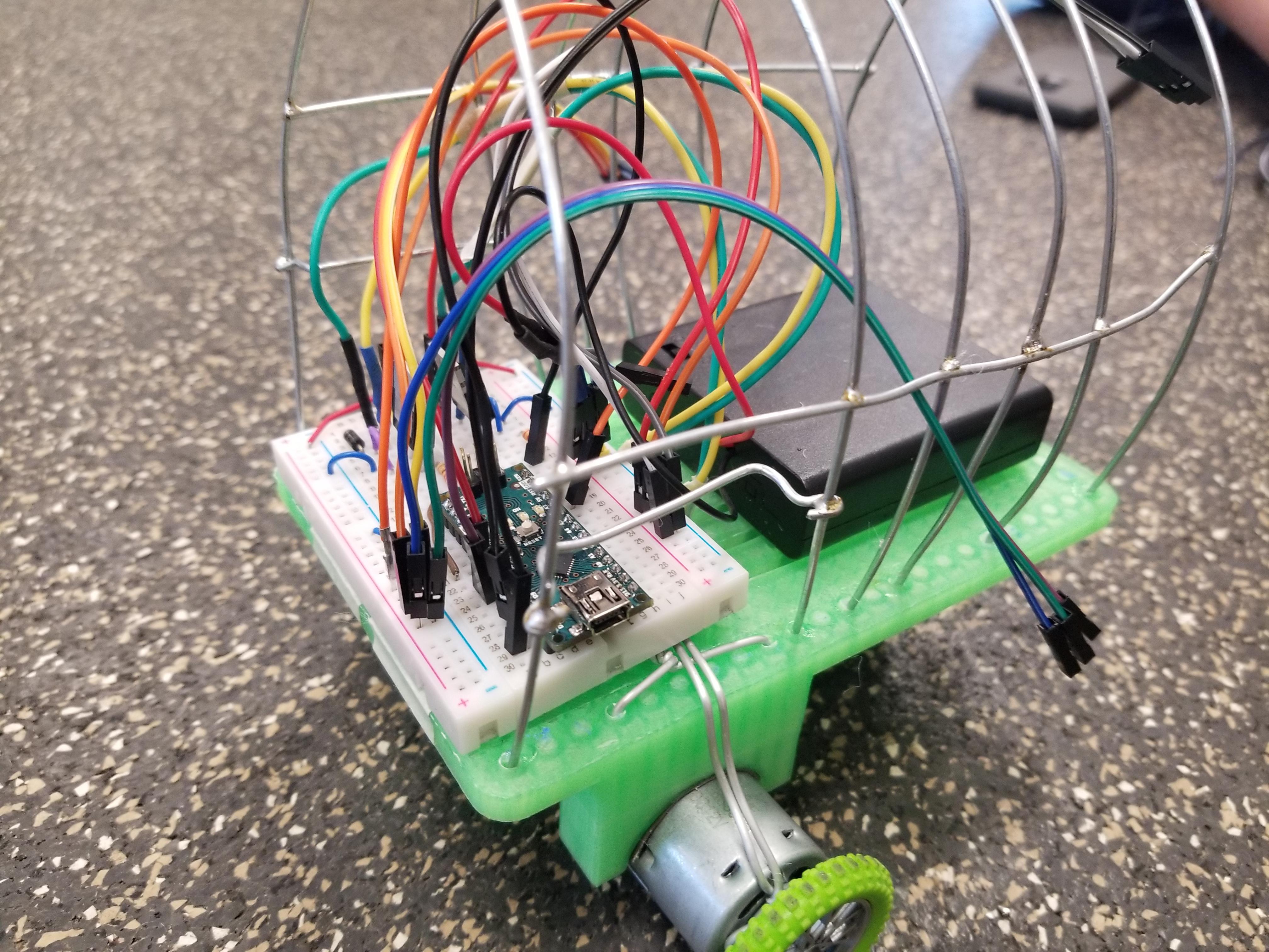
- Put the batteries into the battery holder on the drive train
- Remove the adhesive cover from the bottom of the breadboard and attach it to the top of the drive train. Be careful to check where the USB cable will be coming off of the microcontroller.
- Attach the ground lead from the battery to the lower ground bus on the breadboard
- Attach the power lead from the battery to the lower power bus on the breadboard. Make sure that it is not the same bus that the Arduino power is plugged into.
- Attach the lead from the left motor to the diode that is associated with the MOSFET plugged into pin 3 on the Arduino. One lead should be on each side of the diode. The motors can be plugged in either way. If the motor spins the wrong way when testing, switch the leads across the diode.
- Plug the other motor into either side of the other diode.
- Before putting the plushie over the circuit, make sure that everything works.
- Wrap the plushie over top the frame, making sure the pull the cord through the precut hole
- You may want to put some stuffing back into the fins and the tail