Angry Egg Timer
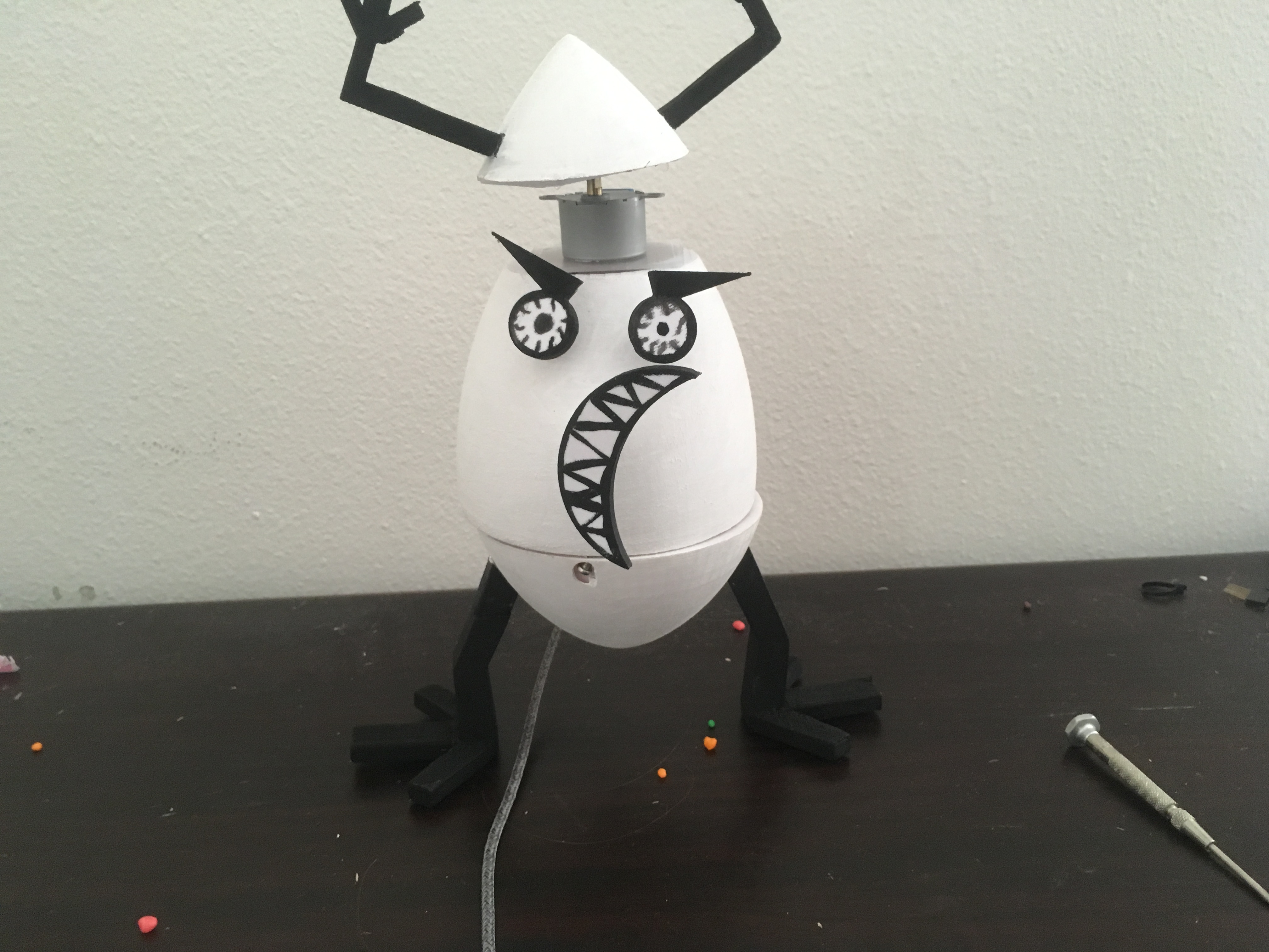
This Instructable was created in fulfillment of the project requirement of the Makecourse at the University of South Florida (www.makecourse.com).
This project is a timer that rotates from a frown to a smile until the chosen time is up, then spins it arms around in victory and "poops" candy as a reward. I've always been fond of using timers and rewards to keep myself focused on studying, and I'm more motivated by silly things than actual motivational content, and thus I decided to make a fairly simple but amusing device to help reward myself for staying focused.
Step 1: Required Tools and Supplies
Required tools and supplies
-3D printer access- can be personally owned or ordered from a lab
-sandpaper and acrylic paint (optional)
-Super glue, hot glue, E6000, or other strong adhesive of choice
-Drill
-3 Small screws- exact size is not important, see what fits firmly in the 3D-printed upper shell
-1 Arduino Microcontroller
-Cable to connect Arduino to computer-An Android charger works well if your board has a microUSB port
-1 Button
-2 SG90 9G servo motors
-Mini breadboard (The smaller the better)
-Jumper wires
-Stepper Motor
-ULN2003 Motor driver module
-Small candy to dispense (Nerds or Pop Rocks would be ideal, mini M&Ms could work, anything much larger could jam the servo)
-Thin plastic or cardboard sheet
-Two LEDs (any color) and 220 ohm resistors (optional, for testing your circuit)
Step 2: 3D-Printed Files
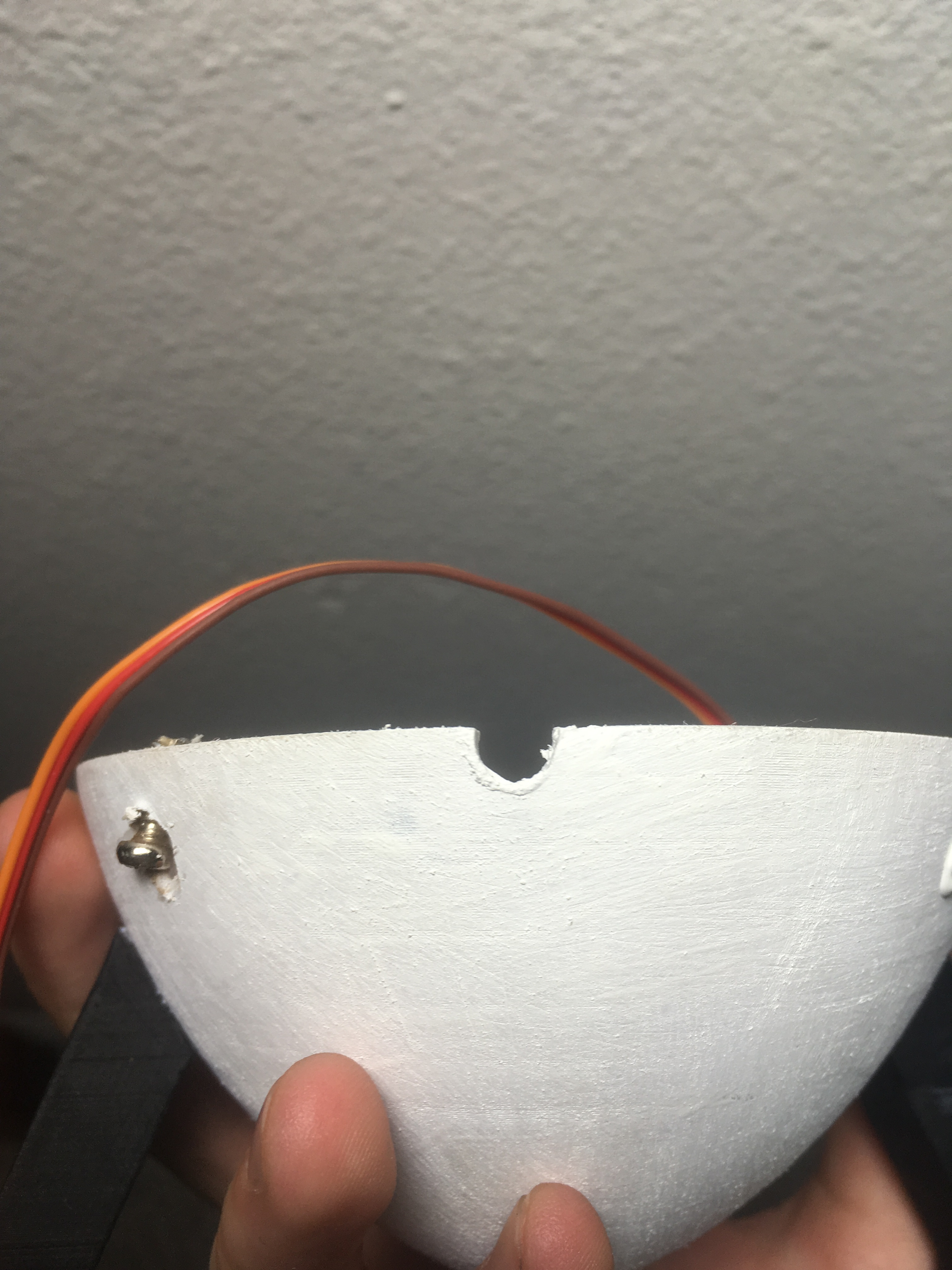
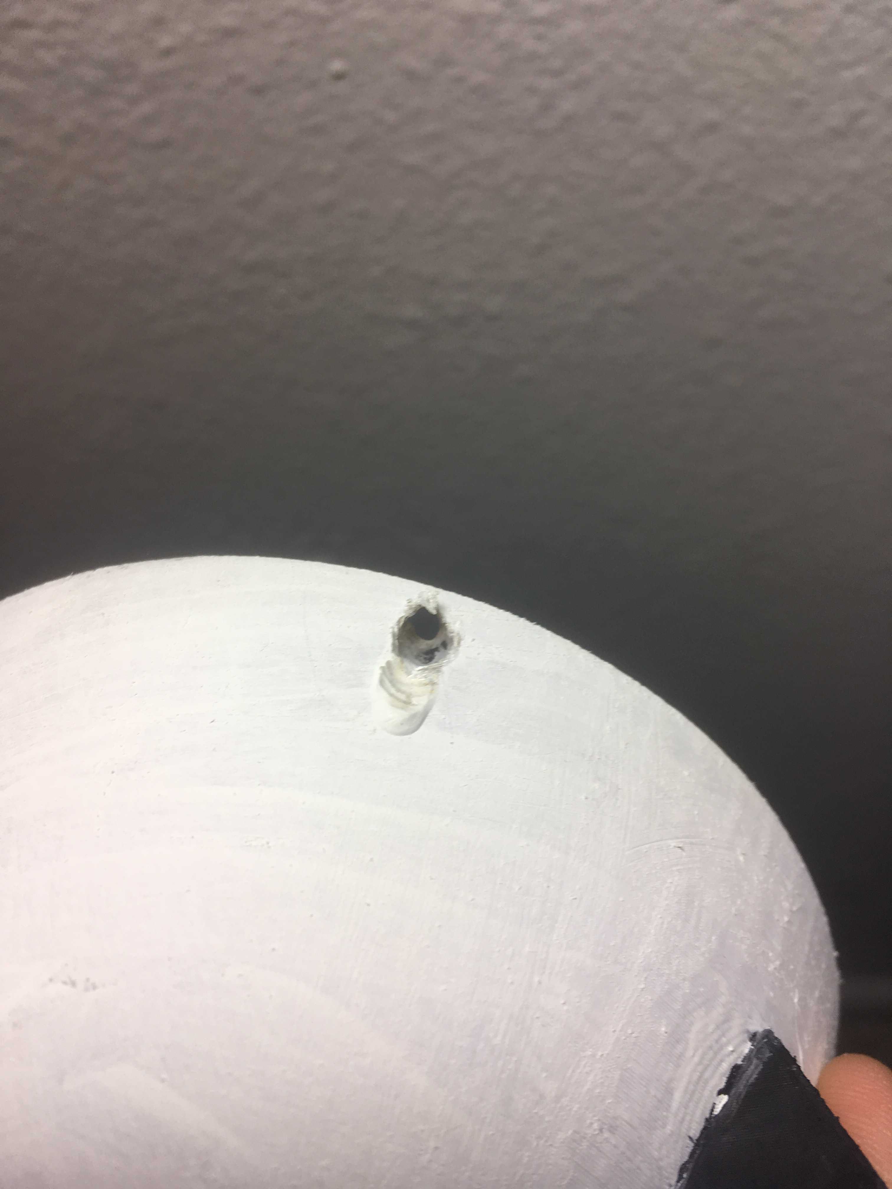
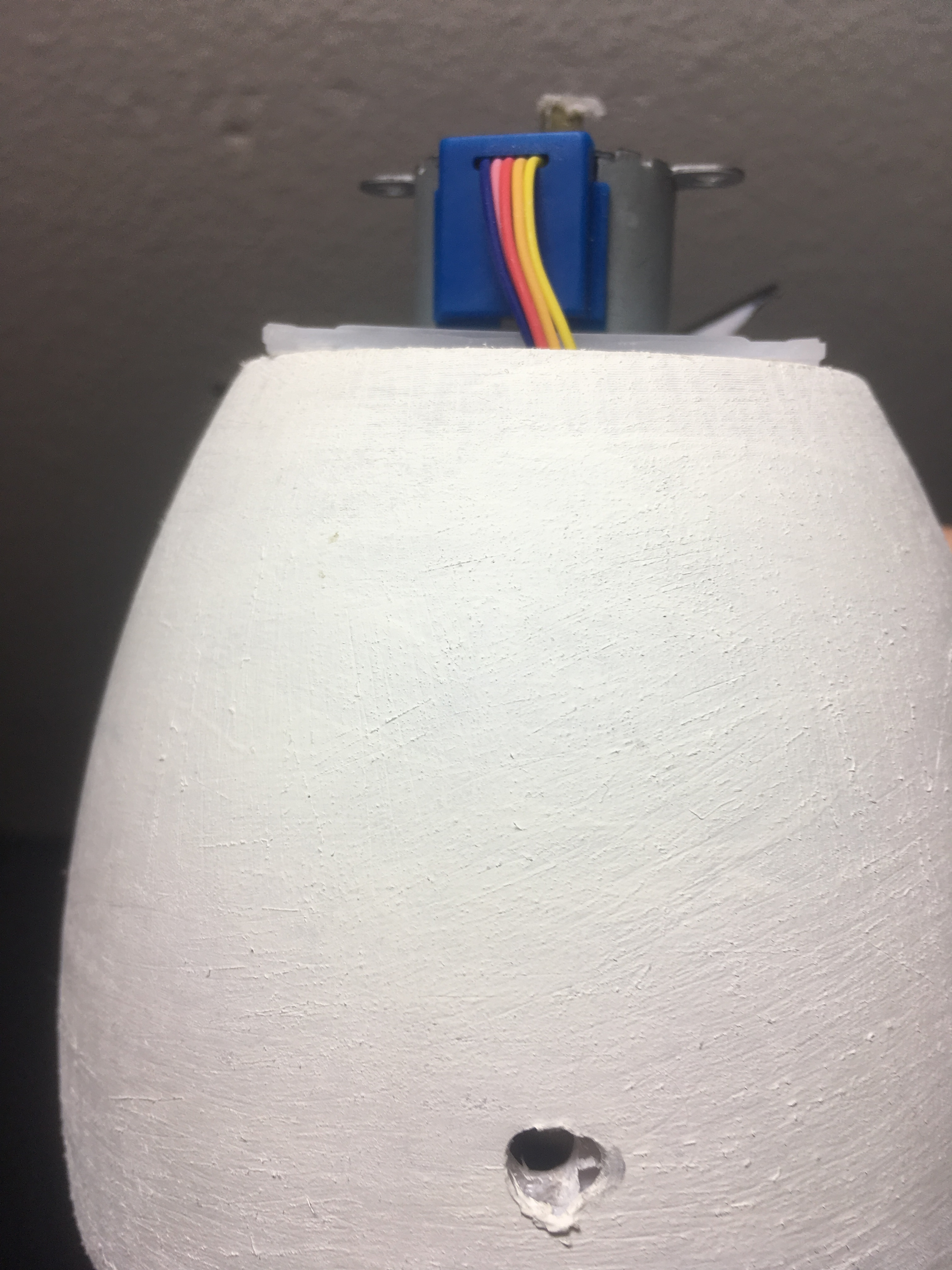
Print one copy of each of these files.
Be careful in removing the supports on the parts as it's easy to snap the arms off the top section. These can be glued back together if it occurs, though. You may need to drill out the three holes if the supports don't come out neatly enough.
Several holes need to be added to the middle and bottom shell portions either by drilling or modifying the files-three screw holes to connect the base and upper portion, a hole for the button, and a groove in the lip of the base for the cable. The screw holes' diameters should be roughly the thickness of the walls of the upper portion and vertical or slightly angled up into the upper half. The size and exact location of the button hole is not too important-it just needs to be large enough to poke a bamboo skewer or other long narrow object in to press the button and somewhere around the middle of the back of the egg. The groove in the bottom section should be the same diameter or larger than your cable. For a matte, more egg-like texture you may wish to sand your parts. Eye and mouth details may also be painted on
Step 3: Circuit Assembly and Testing
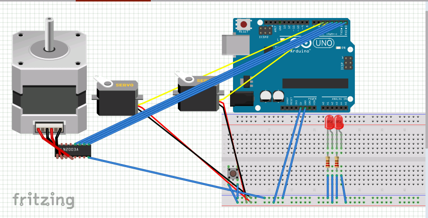
IMPORTANT NOTE- There is a major error in the diagram, power wires for LEDs should attach to pin A4 and A5, NOT the power rail.
The Fritzing diagram above shows the layout of the breadboard. If you know how to properly solder this circuit you certainly may, but as a low-stress application this isn't necessary, though it could save space. The LEDs and resistors and wires connecting them to pins and ground are there for testing your circuit only and may be removed to conserve space.
Pin 5- Smile rotation servo
Pin 4- Dispenser flap servo
Pins 10 11 12 13- Stepper Motor connections
Pin 6- Positive wire for the button
Pin A4 an A5- Positive wire for LED
The locations of power and ground connections on the breadboard can be moved as needed, as long as there is a wire connecting the 5V pin to the positive (red) rail and a GRN pin to the negative (blue) rail and each component has a connection to ground and power. .
Due to problems with the program, the wires are all the same color in the diagram, while color doesn't really matter function-wise, using red wires for positive and blue or black for ground is typical to avoid confusion.
Upload the included code to your Arduino
The servo.h library is a default Arduino library. The stepperAK.h library is included for download above, put these files into the 'libraries' folder for Arduino
The default time interval is 18 seconds for testing purposes. You can easily change this in the code by swapping out that number for your desired time, in seconds. Once your circuit is assembled, testing it is advised. Press the button to start and reset the timer a few times and let it reach its end to ensure the stepper motor and smile and dispenser servos are working properly. The recommended servo model can sometimes be defective and behave erratically is set to a full 180 or 0 degrees, if you have a servo like this, use it for the mouth where this motion isn't a problem and can add the the crazed look of the timer as it spins around before resetting, as it did on mine. If you use a servo like this for the dispenser, it may jam against the inside of the base and damage it or the servo.
When the timer is started, the smile servo should tick 180 degrees until time runs out, after which the stepper motor will rotate twice and the dispenser servo will flip up and down once. If the timer is reset, the smile servo should turn back to its initial position. Take note of how the servos are oriented at the end of the cycle to find the full smile position and closed dispenser position, this is important for assembly. If you have added the test LEDS, one will turn on if the timer is started, the other will turn on when it is reset.
Step 4: Assembly
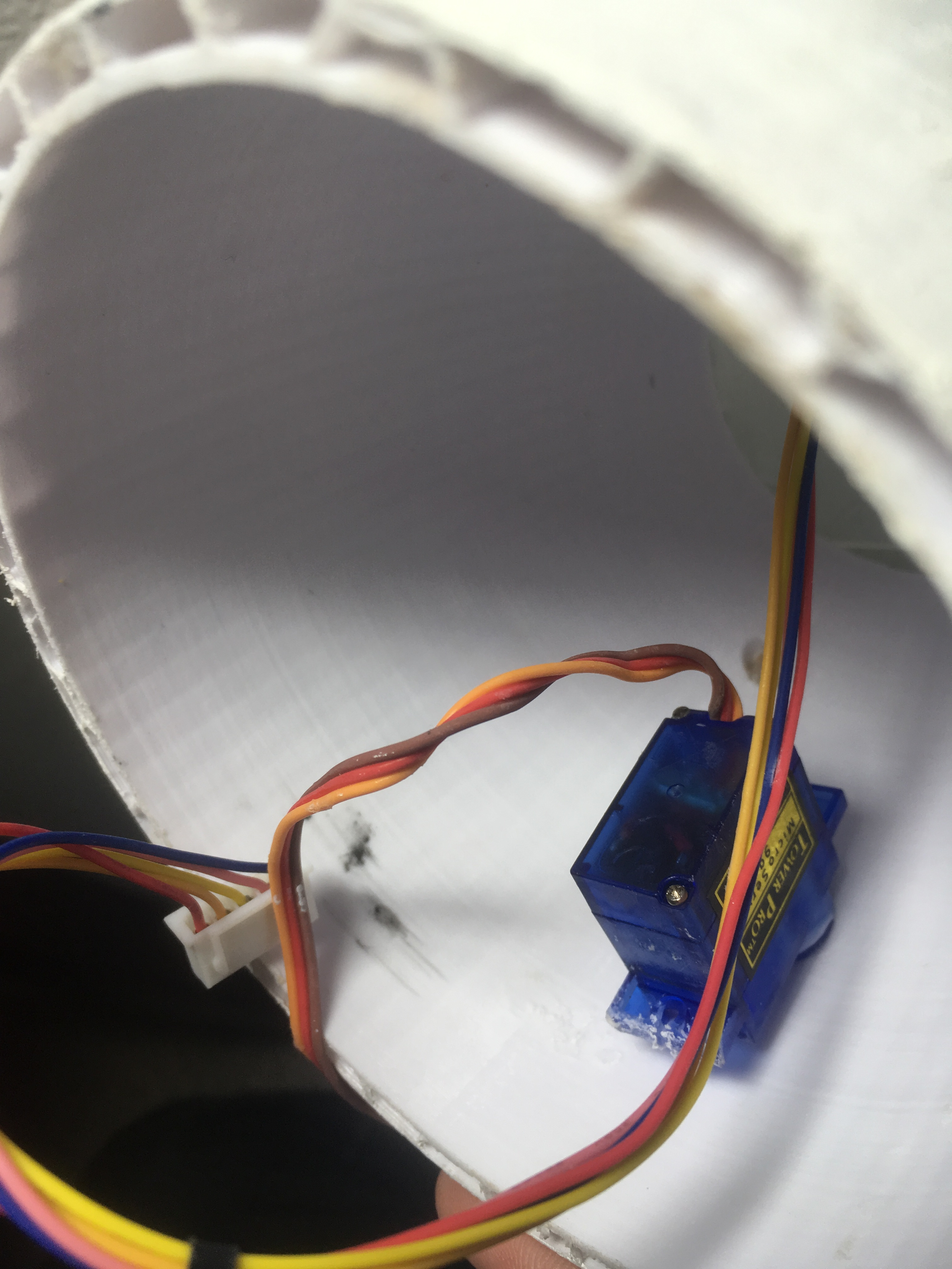
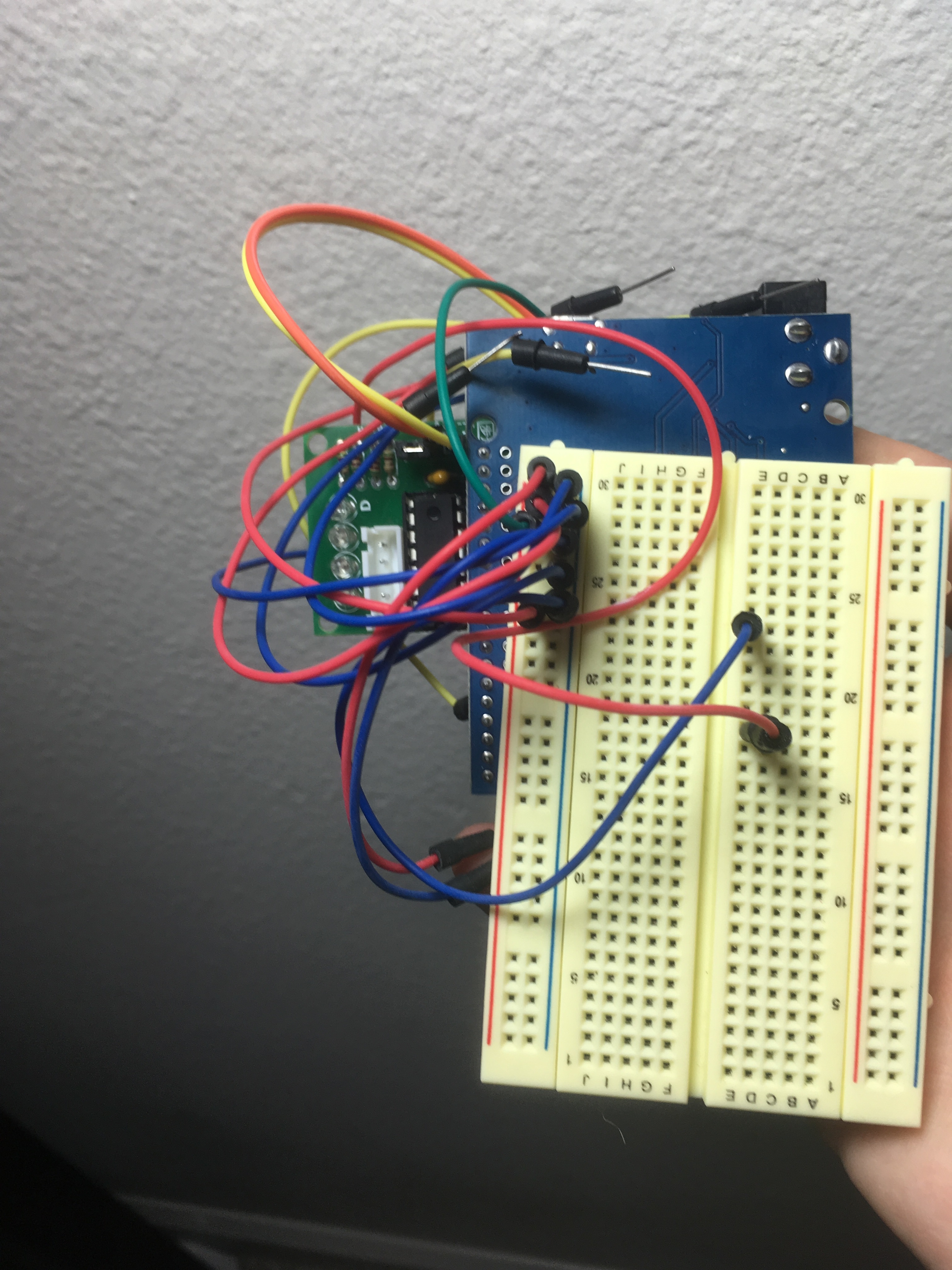
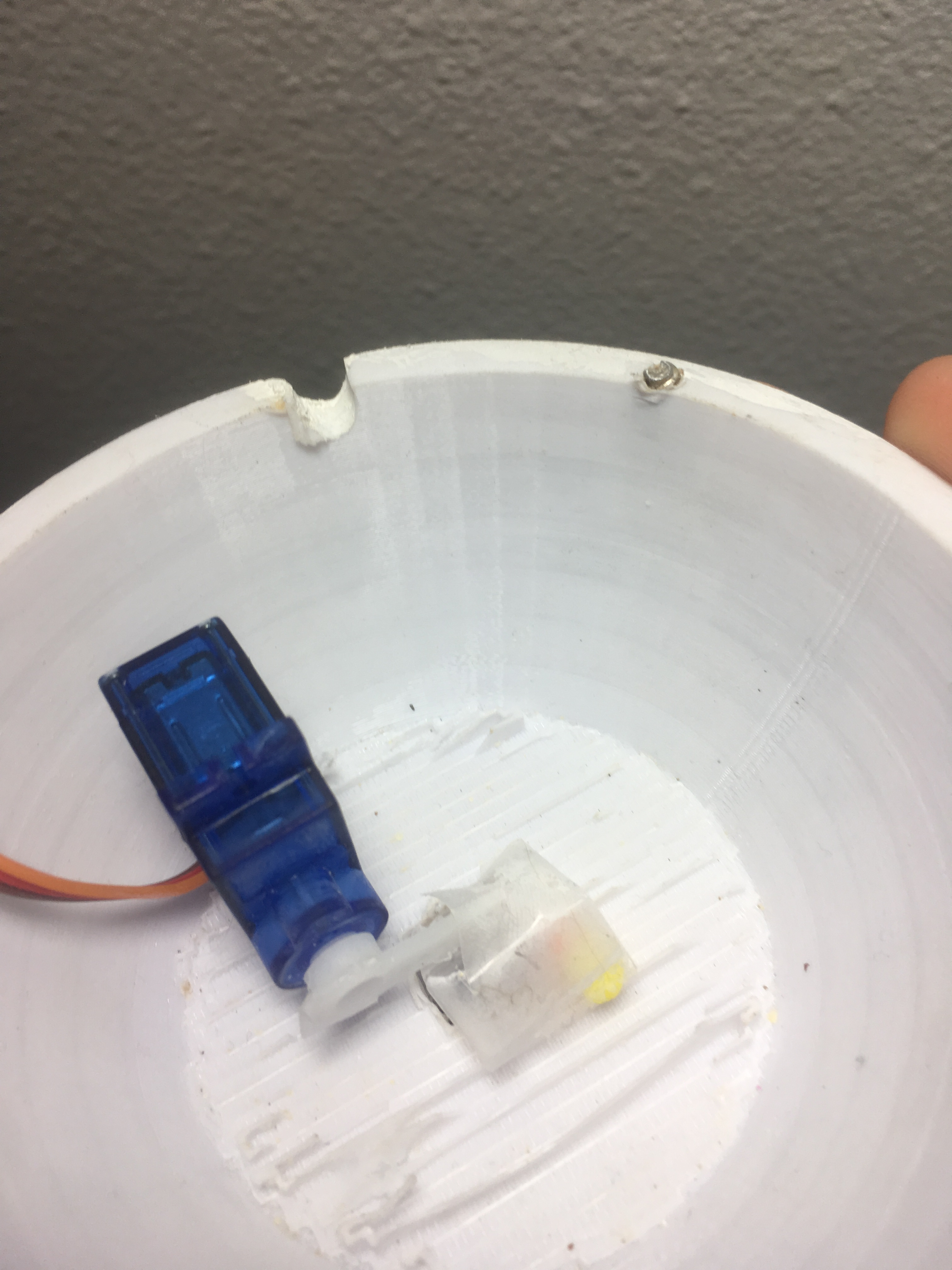
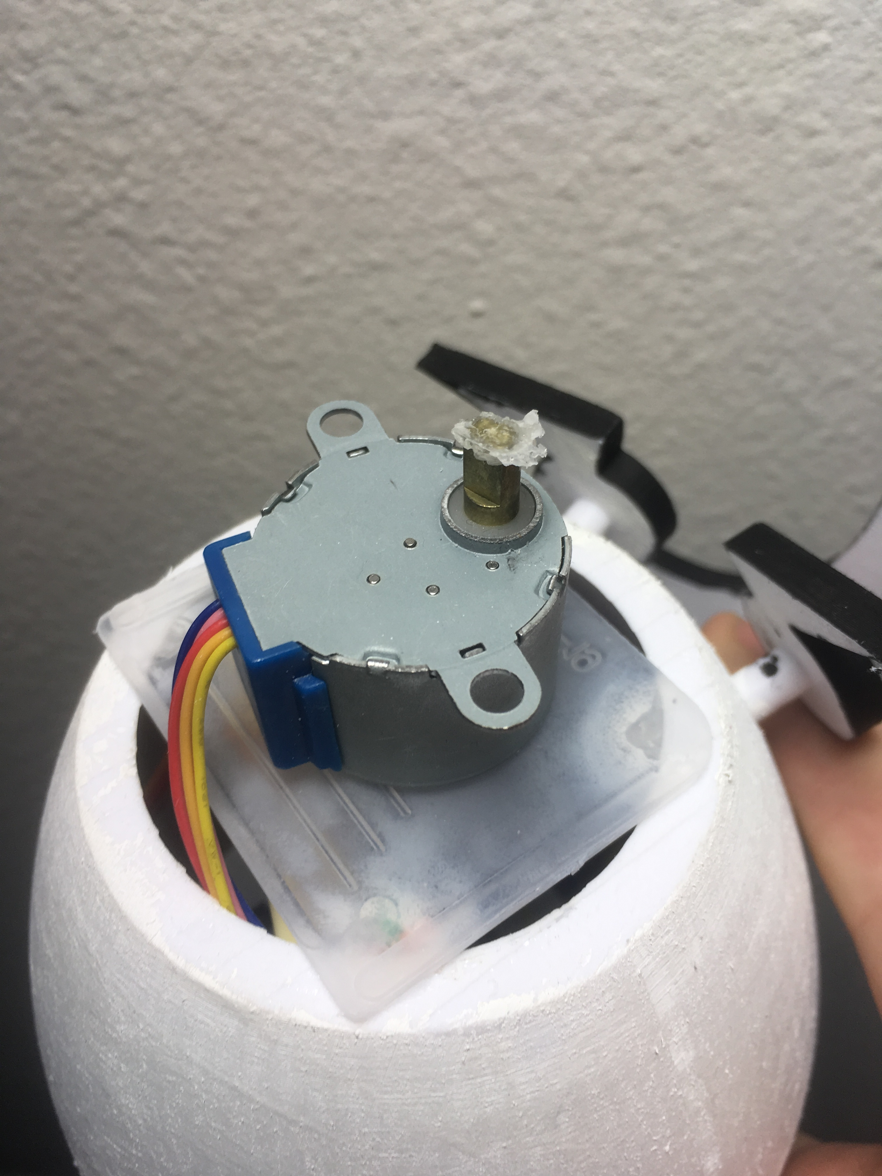
You may need to detach the motors to glue them in place, reference the diagram to put them back correctly.
Glue a small square of plastic over the upper open end of the upper housing component, this is where your stepper motor will sit. Be sure to leave a hole or gap large enough to pass the wires through. If you have enough space to fit your stepper motor inside the body, you may glue this in there instead, as long at the rotating portion of the motor protrudes out the top. Glue another small square of plastic or cardboard to the bottom of the arms portion and then glue this to the rotating part of the stepper motor, trying to attach it as centered as possible. Then glue the stepper motor to the plastic at or near the top of the housing, making sure that the arms are aligned properly.
Remove any tips on the smile servo and glue it to the inside of the upper body with its rotating bit aligned through the hole. Cut off the pointer of one of the heads so it's just a ring and test that it rotates freely. If you use the code provided, at the end of the cycle it will be in the full smile (180 degree) position. Glue the smile piece to the tip of the servo motor so it's oriented properly.
Attach a one-ended pointer to the dispenser servo and then glue a tiny flap of plastic to it as pictured, making sure that it allows full rotation while mostly covering the bottom hole. Test your code with the dispenser servo to find its initial position to ensure it won't jam, then glue down the servo so it covers the hole in its initial position.
Fitting the components into the small housing is more an art than a science, you can experiment with different layouts to see what fits. Positioning the Arduino and breadboard flat against each other and oriented vertically with the connector cable pointed down worked best in my experiments. Removing the testing LEDs will save space. Putting the electronics in with the body flipped upside-down makes fitting them in a bit easier with gravity assisting you. Be sure that your button is close enough the the hole that you can reach it with a long, narrow implement like a bamboo skewer or small screwdriver tip. Once you have everything packed in, test the circuit again to ensure nothing fell out and that the dispenser servo is able to move freely.
At this point, you'll want to put your candy in the bottom of the body. Now screw the small screws into their holes to secure the middle and bottom body sections. You can unscrew these for repairs and candy refills later if needed.
Finally, the eye pegs should fairly neatly fit into their appropriate holes, you may need to drill them out a bit if they don't. Glue these in place, placing them as symmetrically or asymmetrically as desired.