Andy - the Robot Arm
Hello everyone!
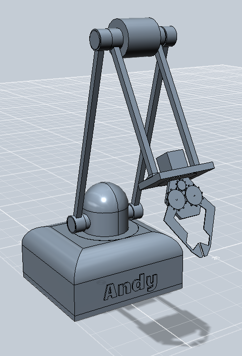
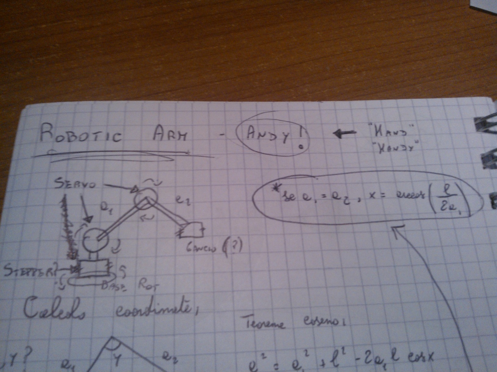
I am here to introduce you to Andy. It is a robotic arm, and its name is a reference to the words "hand" and "handy" - that well fit with a robotic arm.
The idea was born during my holiday: a robotic arm that can rotate, stretch and shrink, able to do quite everything you want it to do, inspired by industrial machines.
Andy has a rotating base, two joins that can be rotated independently (think at them as human's shoulder and elbow), and a claw that can be rotated, opened and closed more or less strongly as you need.
The system is completely based on Arduino. Stepper and servo motors will be used.
The introduction is finished: let's design!
The Base
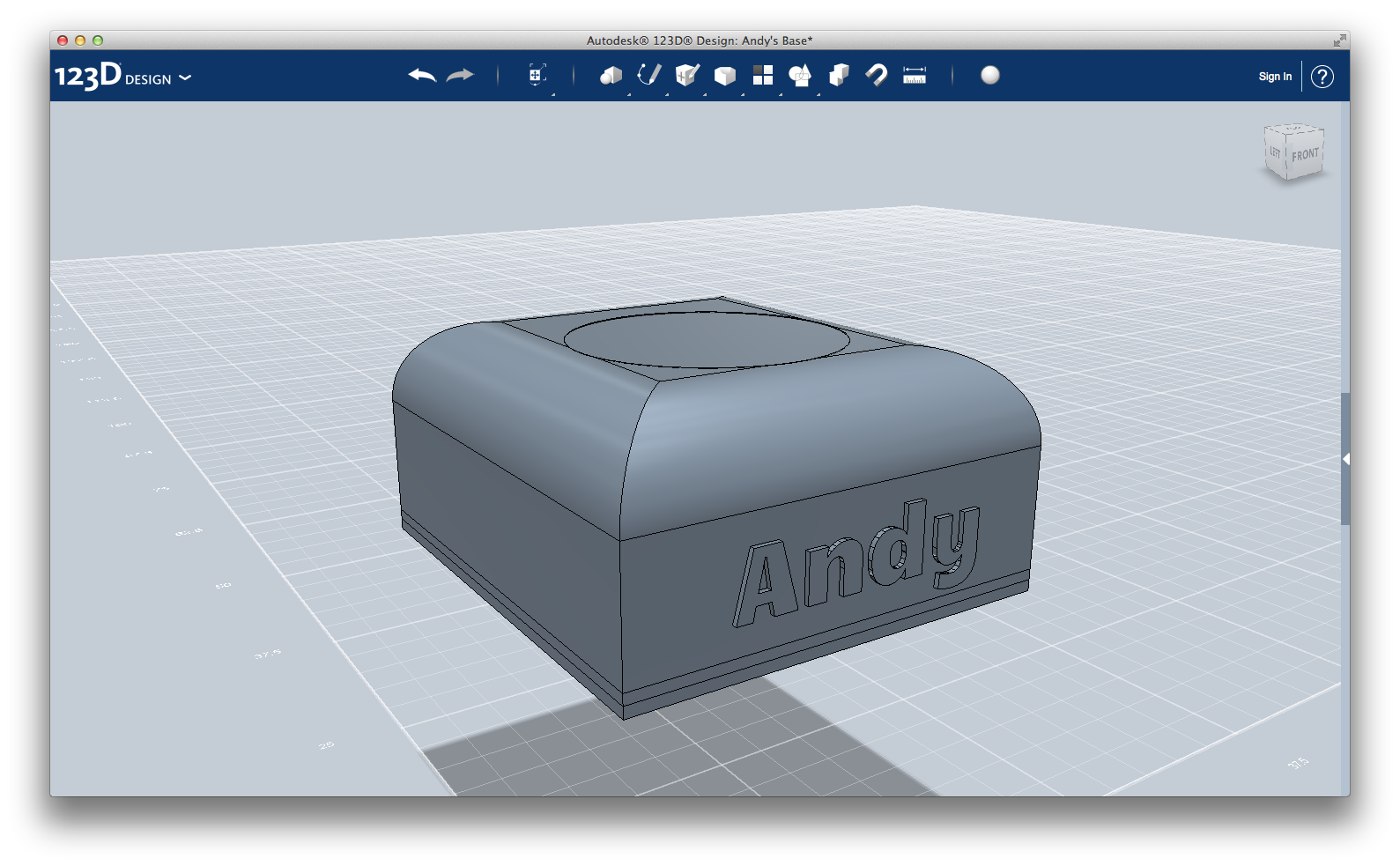
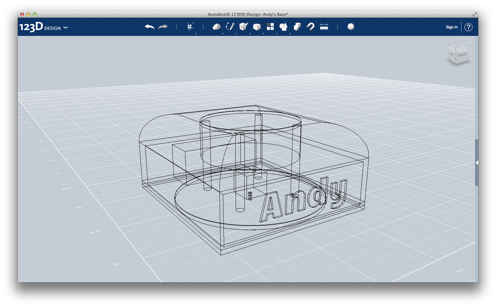
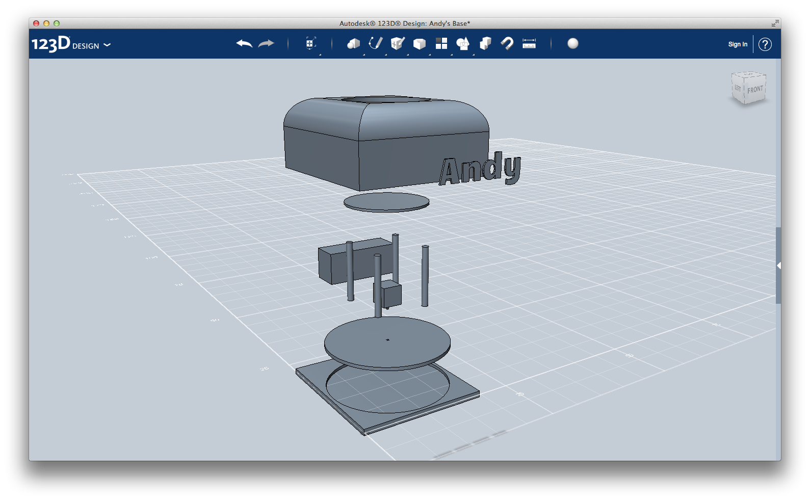
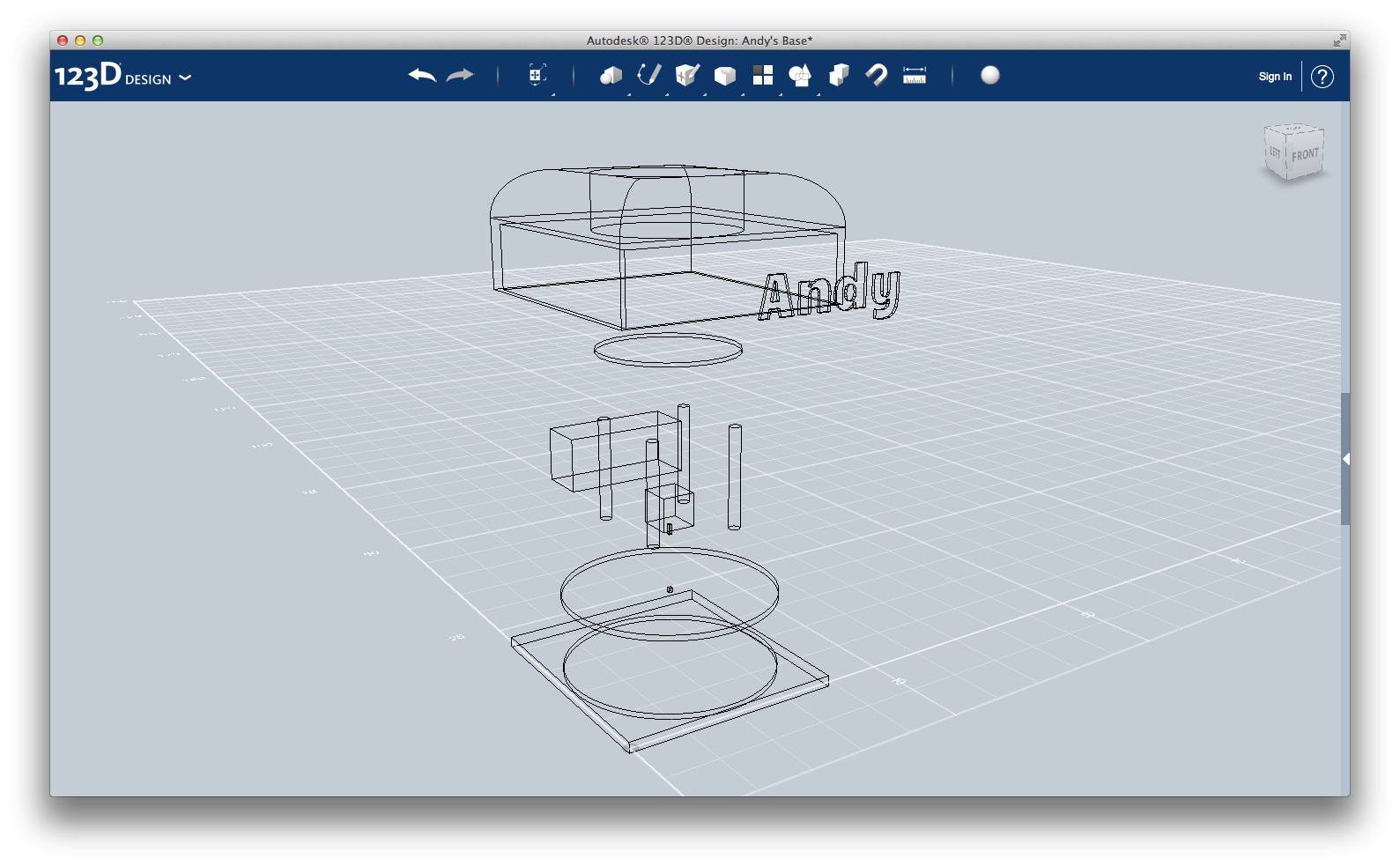
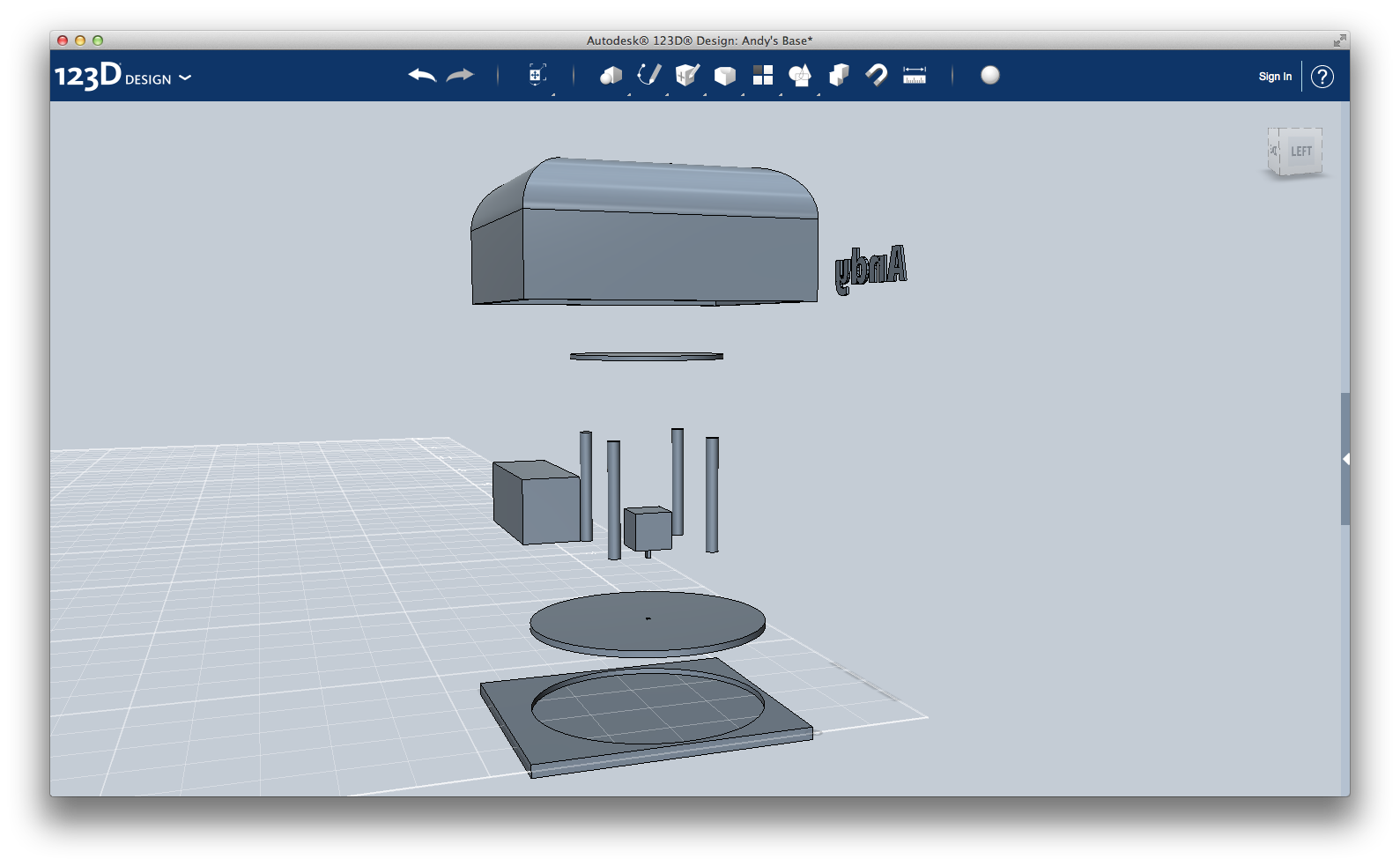
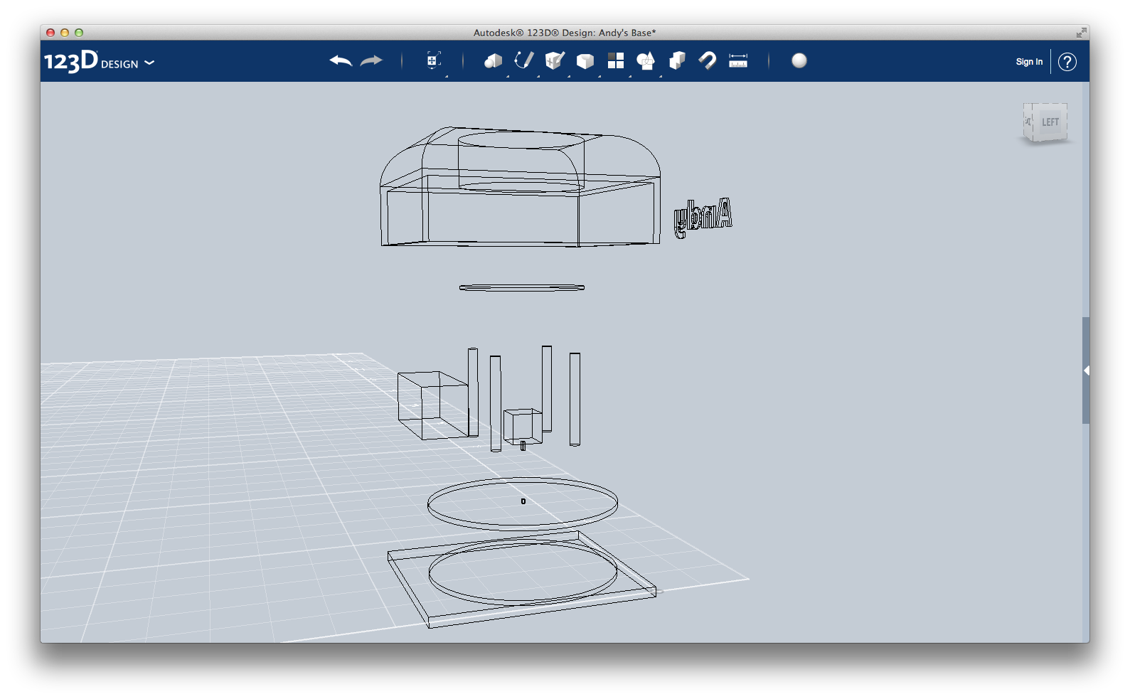
First of all: the base.
It has to be solid enough to hold up the whole arm, but also able to rotate.
Furthermore, it's in the base that the electronic system (Arduino) will take place.
Let's analyze the design.
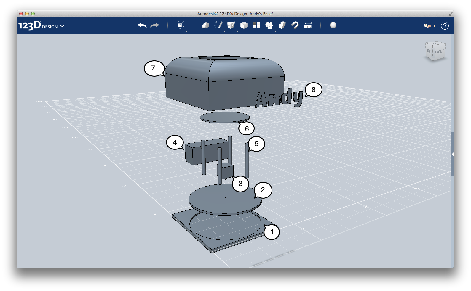
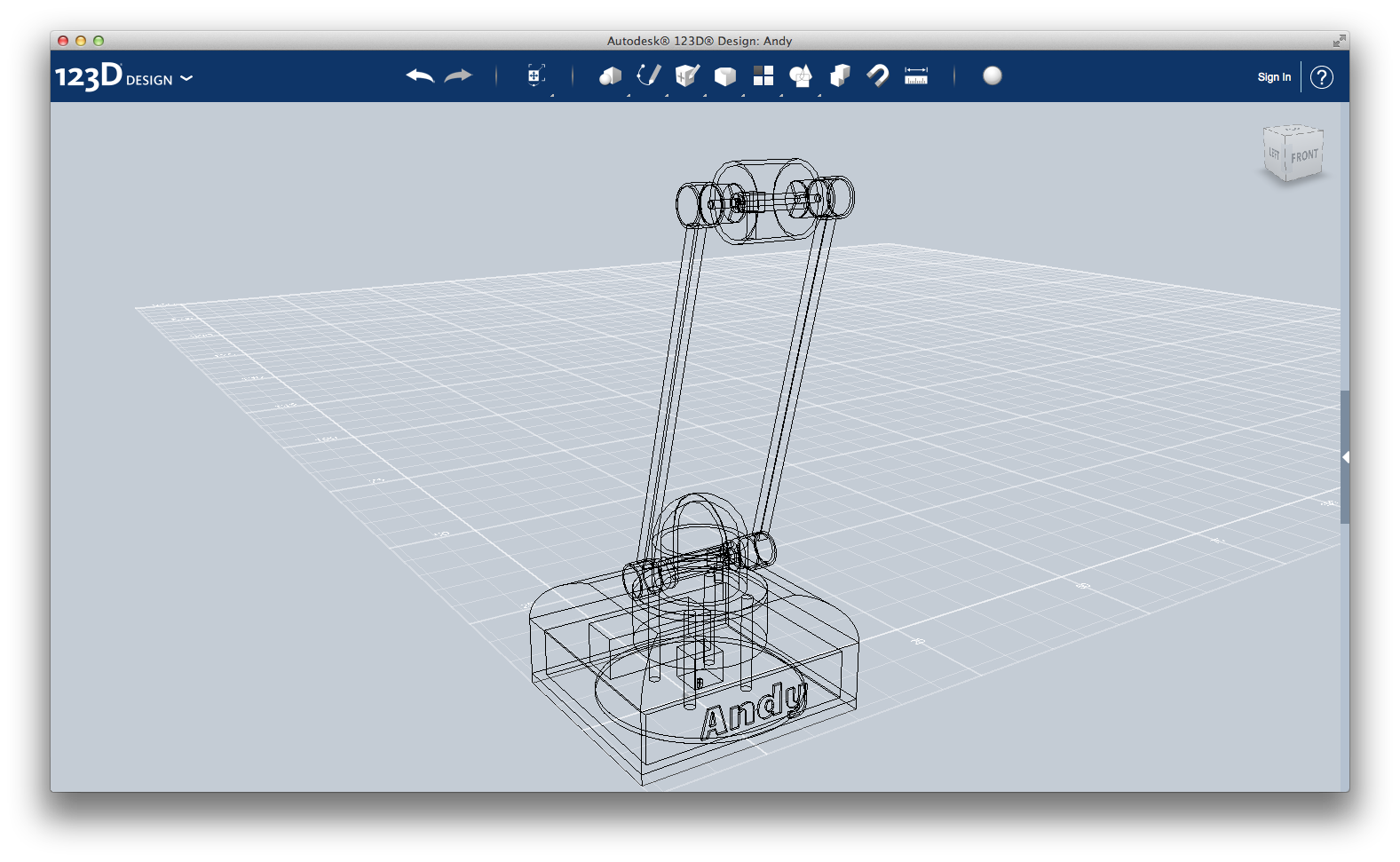
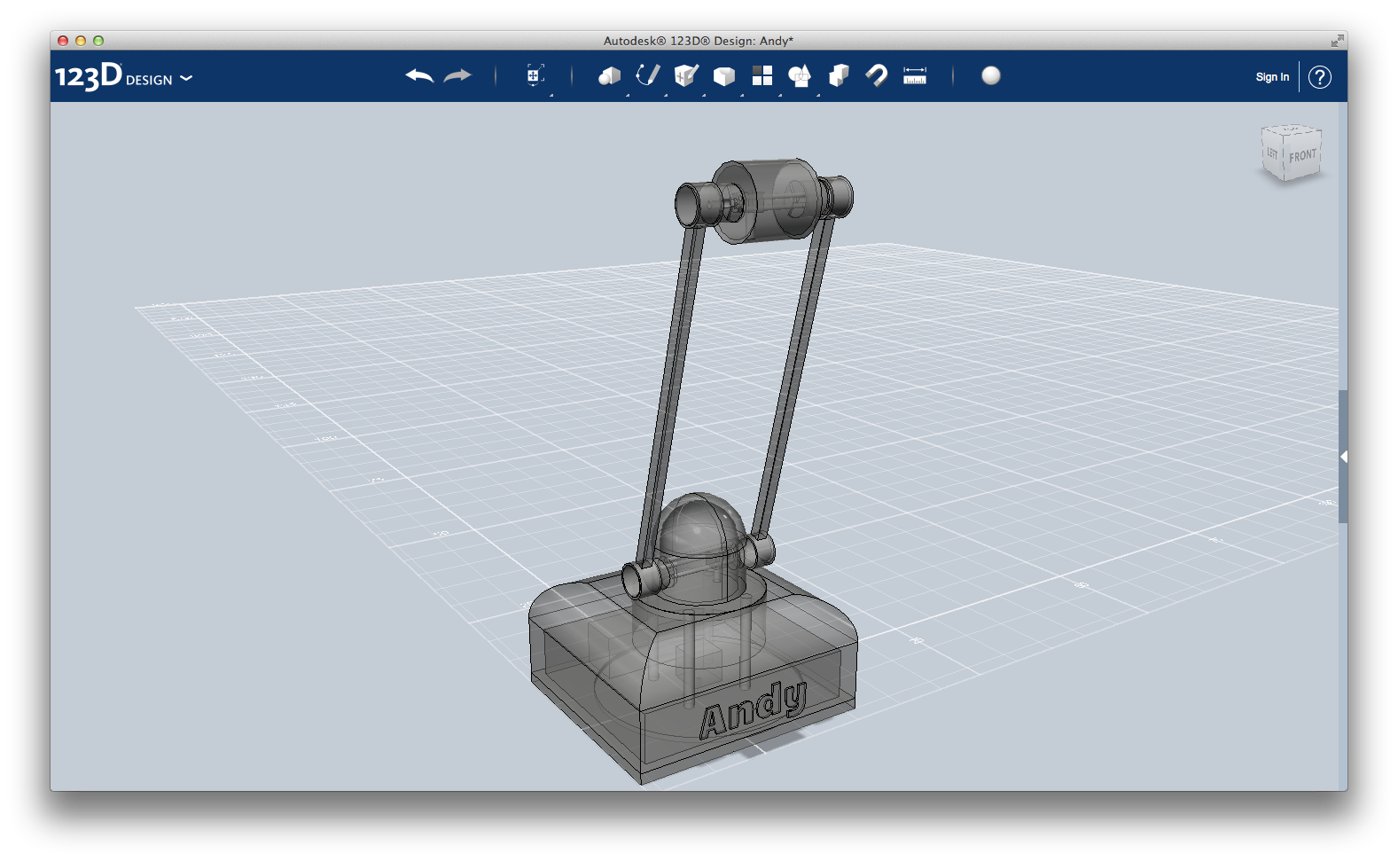
On the base (1) is placed a disk (2), that rotates thanks to a motor (3). It is wired with the Arduino board, placed in the apposite box (4). This rotation is transmitted with four pins (5) to a second disk (6), that is where the rest of the arm will lie. Finally, an enclosure (7) complete the base.
Here is the procedure to recreate the design: don't worry about measuring units (mm, cm, ...), you can resize the whole thing when you have finished.
1) The base: create a box of size 20x22x1 units. Create a cylinder of radius 9.5 units, align it on one side of the box, and subtract from the box creating a circular hole 0.5 units deep.
2) The bottom disk: use the same radius (9.5) to create the disk, height 0.5. Using a 0.3x0.3 units based box create a hole at the center of the disk. The motor gear will fit in there and make the disk moving.
3) The motor: create a 3x3x3 box. Attach at the center of one face another box that measures 0.3x0.3x0.9. It is the moving part of the motor, and it will be connected to the disk.
4) The electronics: we need a box containing Arduino and other electrical components: just create a box that measure about 4x11x4 units.
5) The transmission: the bottom disk rotation is transmitted to the top disk through four pins. Just create four identical cylinders of radius 0.5 and height 9 and place them symmetrically to the center of the disk.
6) The top disk: create a cylinder with radius 6 and height 0.6. Place it on top of the four pins.
7) The enclosure: create a 20x22x10 units box. Select the four top edges, and use the tool Fillet with radius 4.
Create a rectangle that overlap the box bottom face, using the Sketch > Rectangle tool. Using Sketch > Offset create a smaller rectangle, taking away 1 unit from each side. Now, use Modify > Extrude with the setting Subtract and drag the rectangle up for 5 units. Then click anywhere on the workspace: your enclosure is now empty inside.
Using the top disk as reference, make a hole on the box using the Combine > Subtract tool.
8) The name: as every respectable project do, my arm needs a name. Open the menu on the right and select Primitives > Smart Primitive > Text. When the primitive is load, change its text to "Andy". Then resize it and place it on the frontal face of the enclosure.
Please note: The motor is fixed in its position using a block connected to the electronic box or to one side of the external box. It is not included in the picture. Moreover, the electronic box needs at least one hole, in order to take out the wires that will connect the motors with Arduino.
Andy's base is ready!
In the next step, I will create the first joint and sub-arm.
First Joint
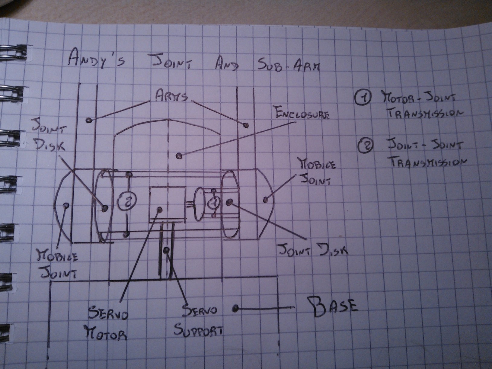
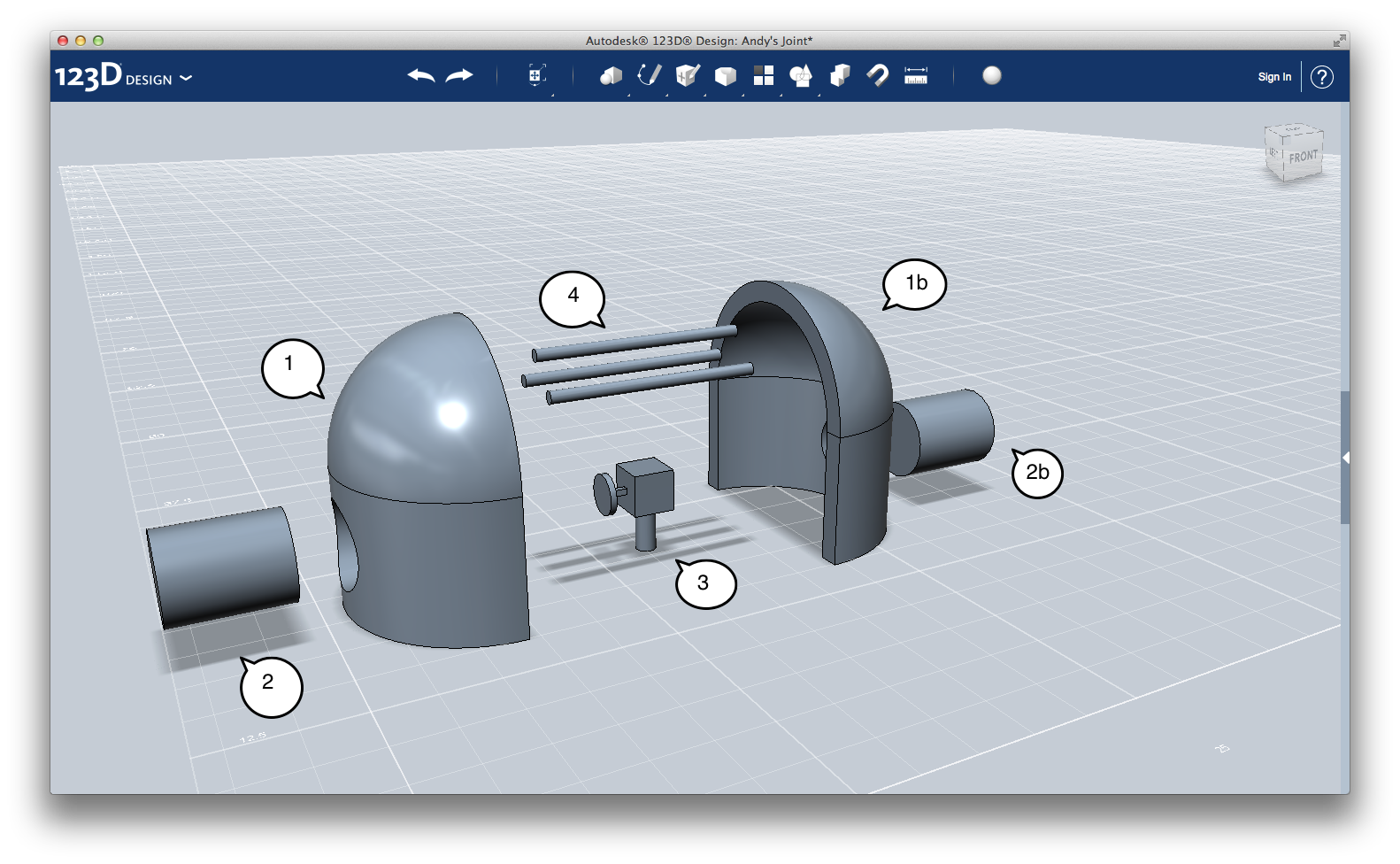
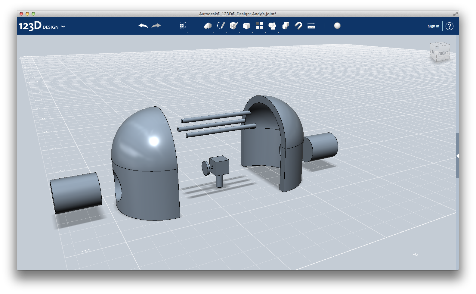
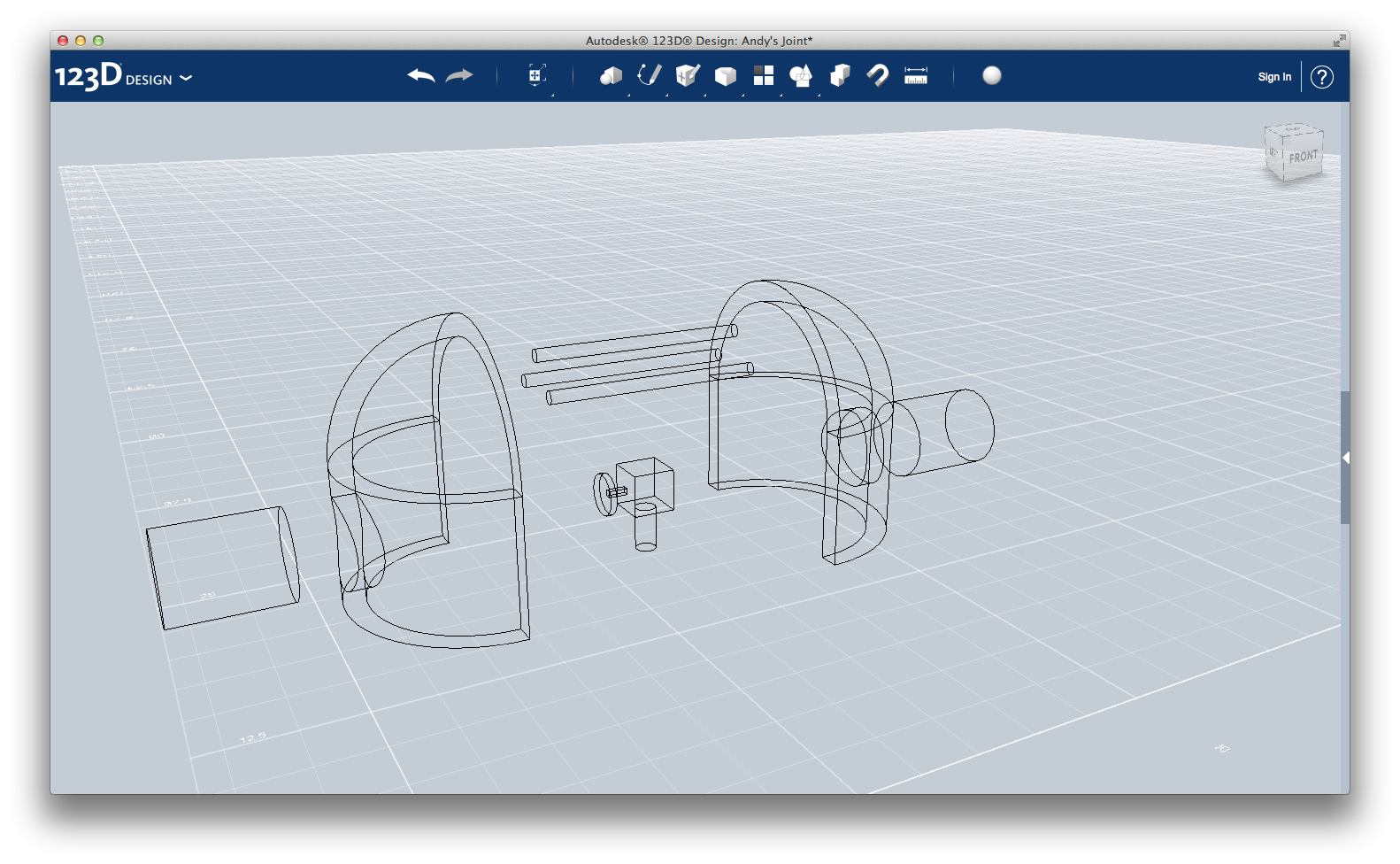
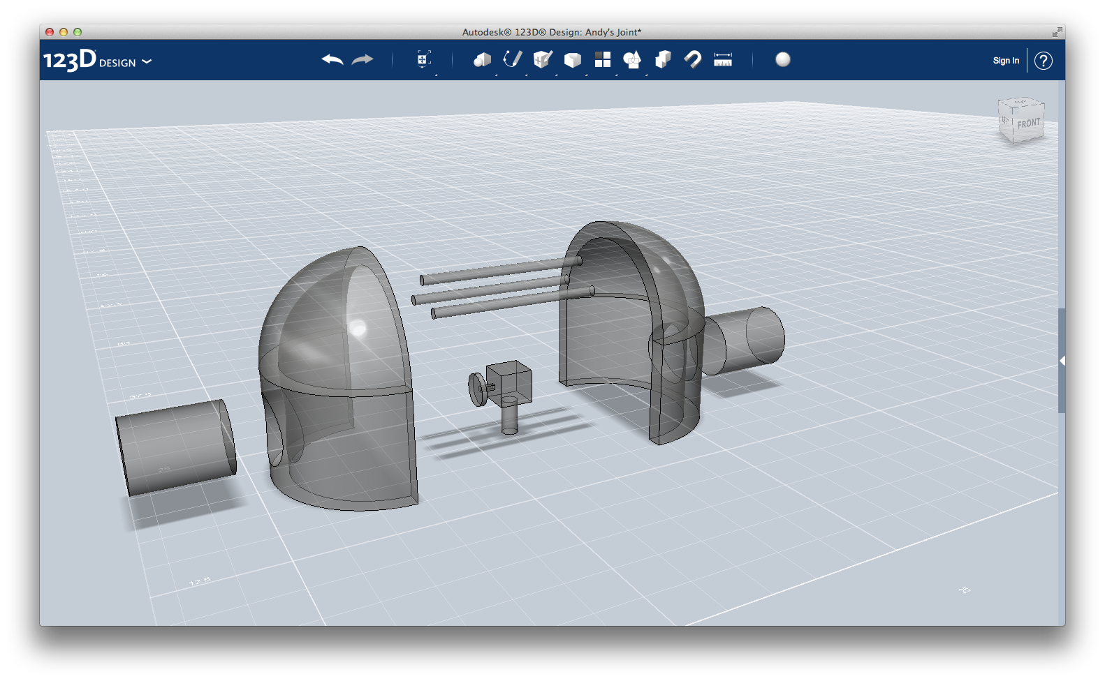
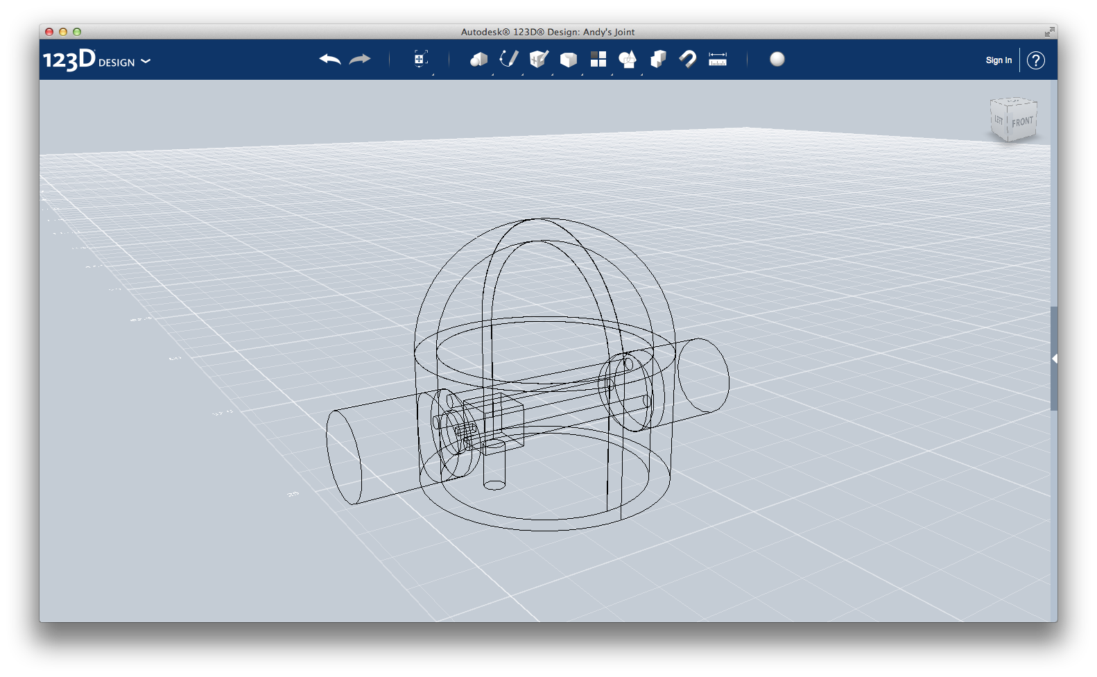
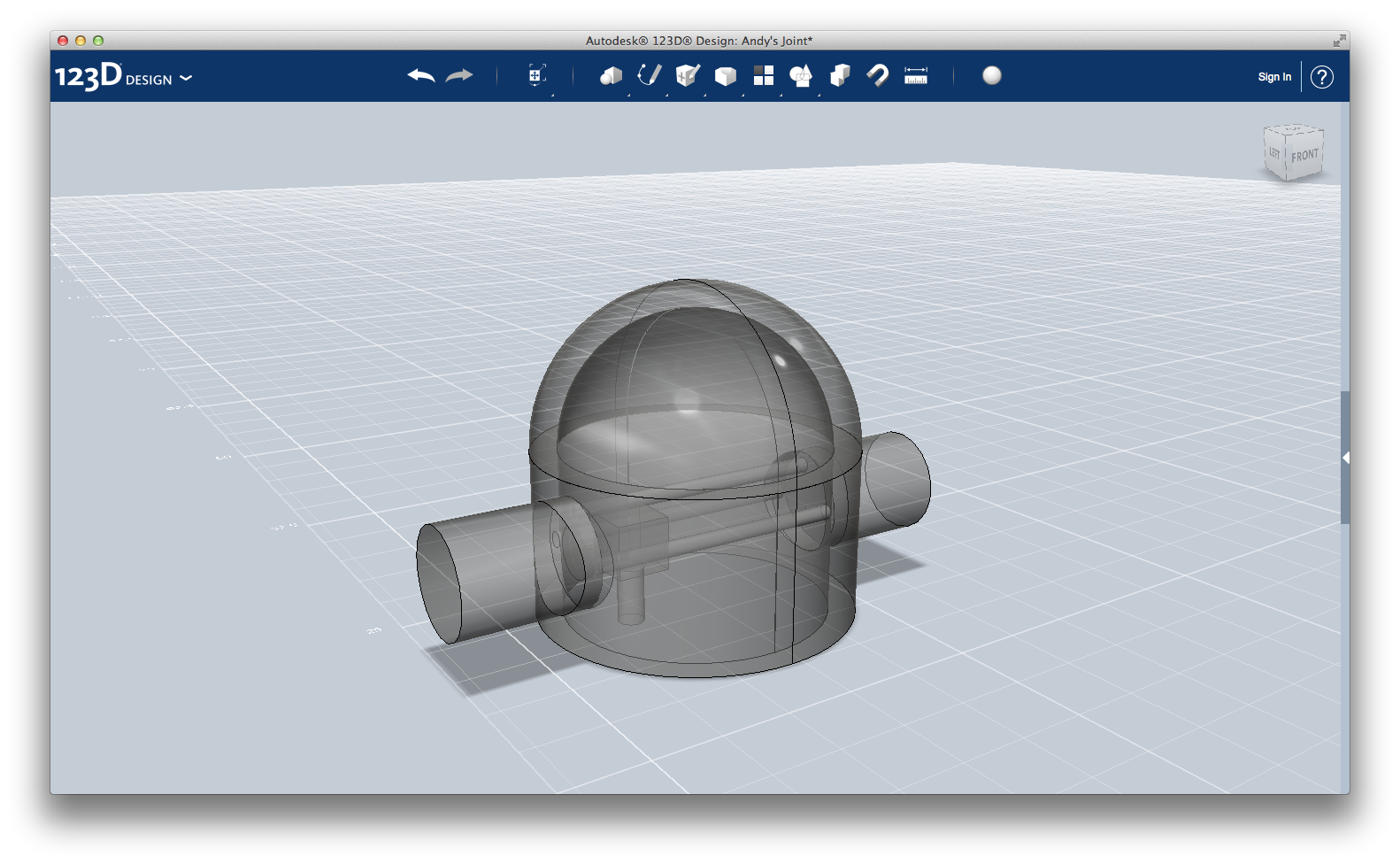
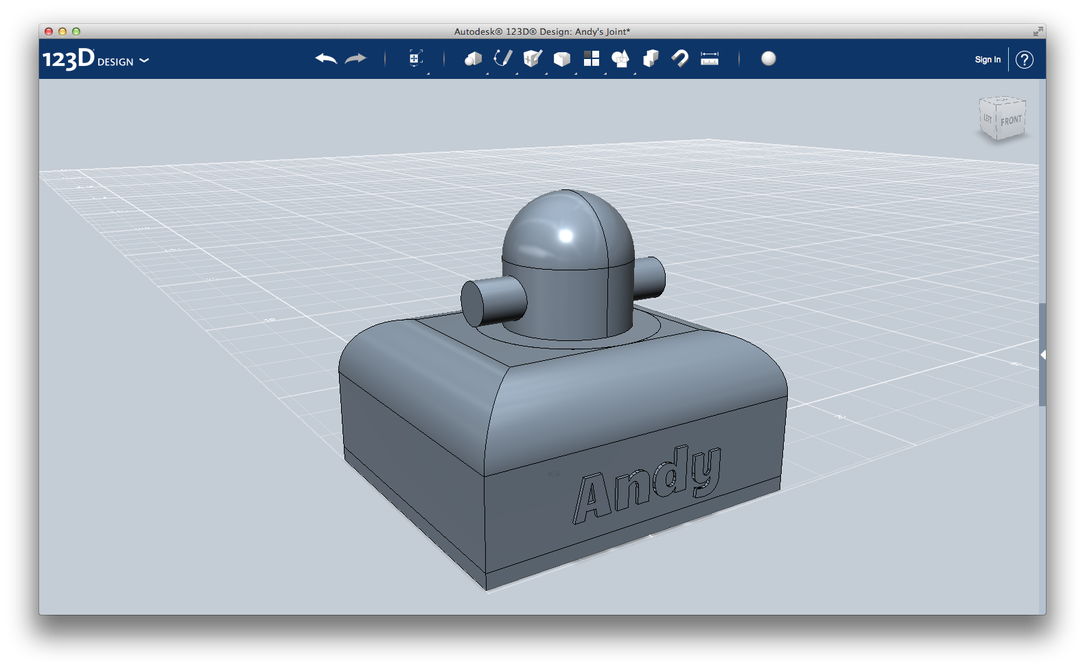
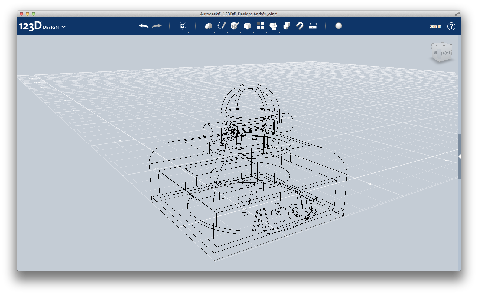
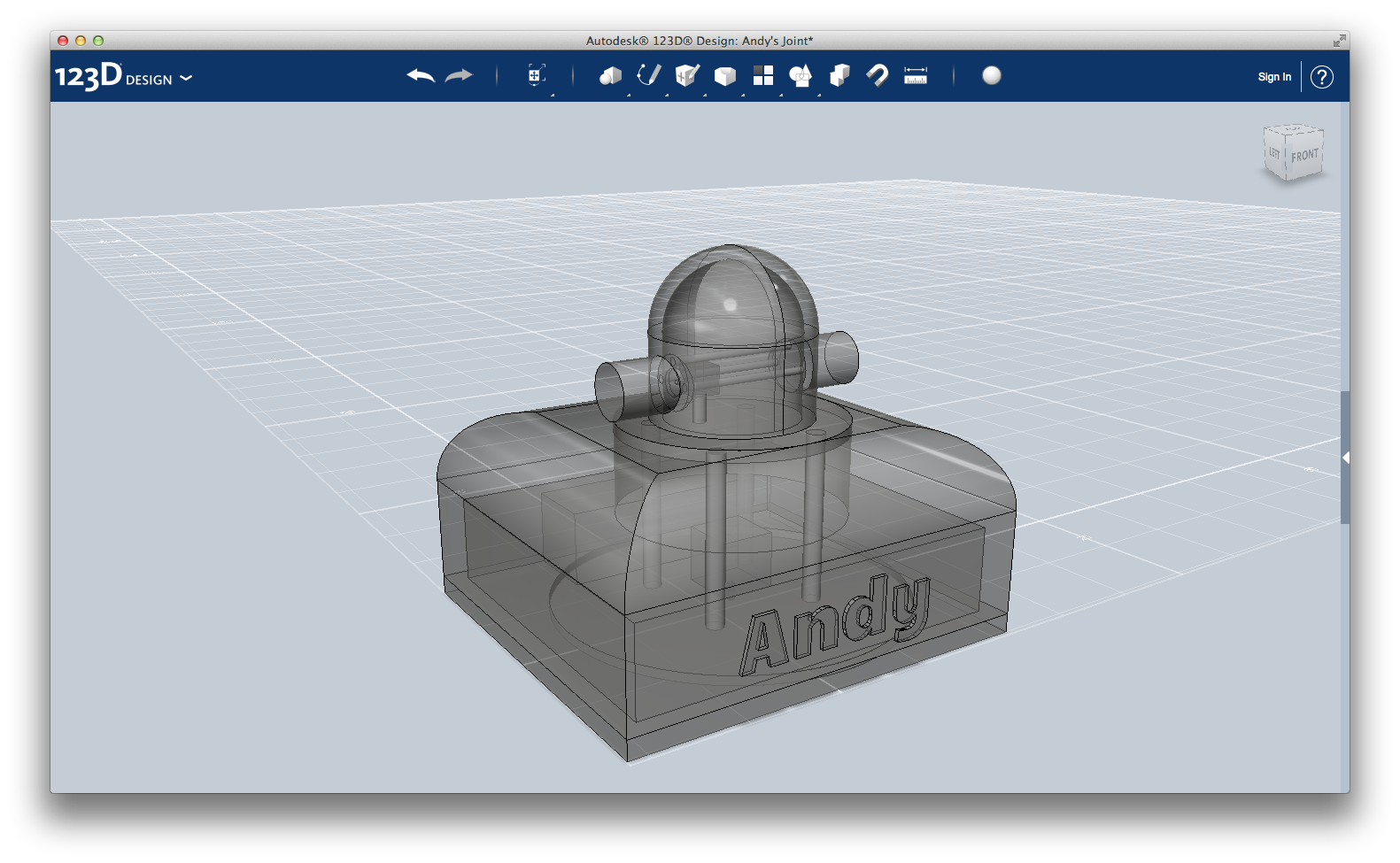
Now, let's focus on joints.
As I said before, Andy has two joints that act like human's shoulder and elbow. These joints are rotating parts that hold up the arm and make it able to reach any point around it.
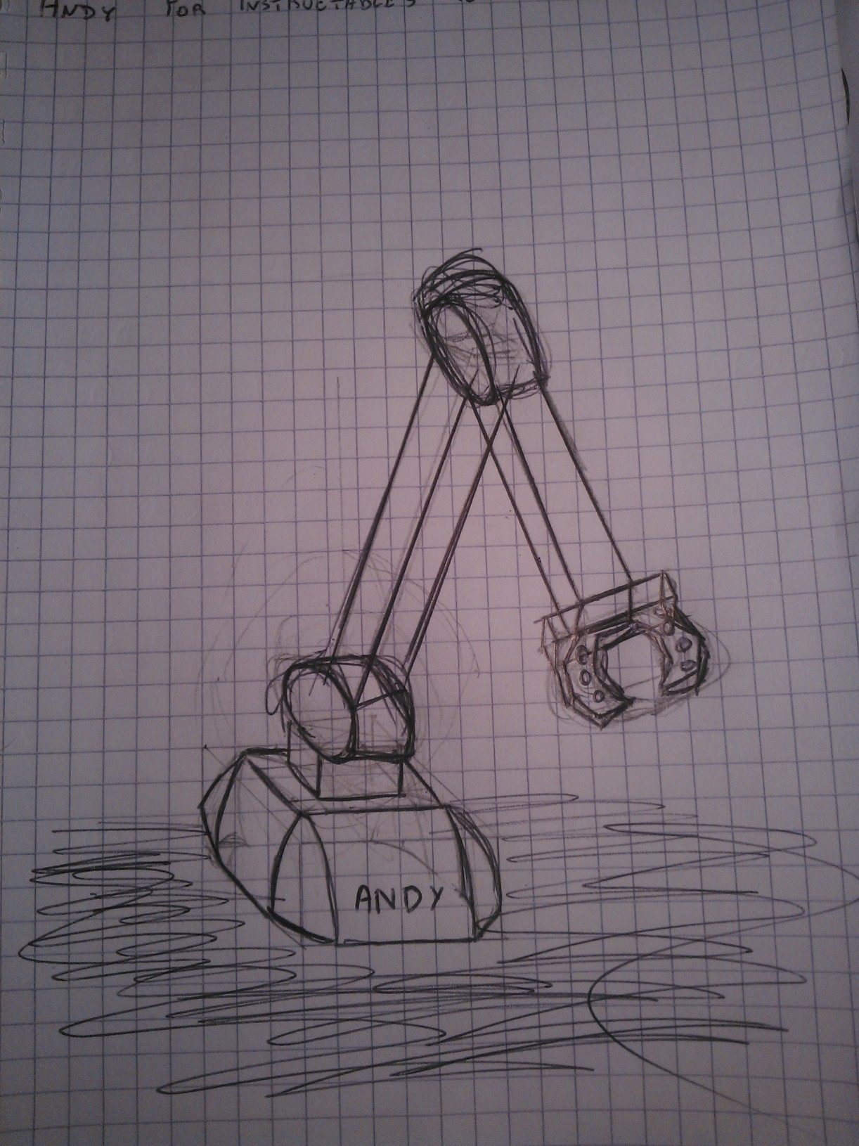
Before starting with any design software, it is useful figure out how your product will look alike, and sketch it on the paper. You can see my idea in the main picture above.
Comparing this arm sketch with the first drawing of this Instructable, you can see how the design has changed. Instead of a big, heavy block, now there are two slim rods connected to the next joint. In this way, thinness is obtained without losing stability.
Here the instructions to recreate the design of the first joint:
1) First half of enclosure: create a cylinder of radius 4.20 and height 4.30. Put on it a sphere of the same radius. Using the Sketch > Rectangle and Modify > Extrude > Subtract cut it in half. Then, with the Sketch > Offset tool, empty the body leaving a margin of 0.70.
Finally, create a cylinder with radius 1.40, and using the Combine > Subtract tool, use it to cut off a circle on the body of the main cylinder, as you can see on the pictures.
2) Rotating cylinder: just create a cylinder with radius 1.40 and height 3.50.
1b and 2b) Simply copy & paste part 1 and 2, and rotate it of 180 degrees.
3) This represents the servo motor: its body is a cube with side 1.40. On the bottom, a cylinder with radius 0.35 and height 1.50 support it. The movement is transmitted through a disk (radius 0.70 and height 0.20 cylinder) connected to the motor with a 0.2x0.2x0.6 box.
4) This three parts transmit the movement from one side of the joint to the other. Create three identical cylinder with radius 0.2 and height 7. When you are assembling the whole thing, place it simmetrically on the top, left, and right side of the servo disk.
Tip: use the Snap tool to assemble the parts together.
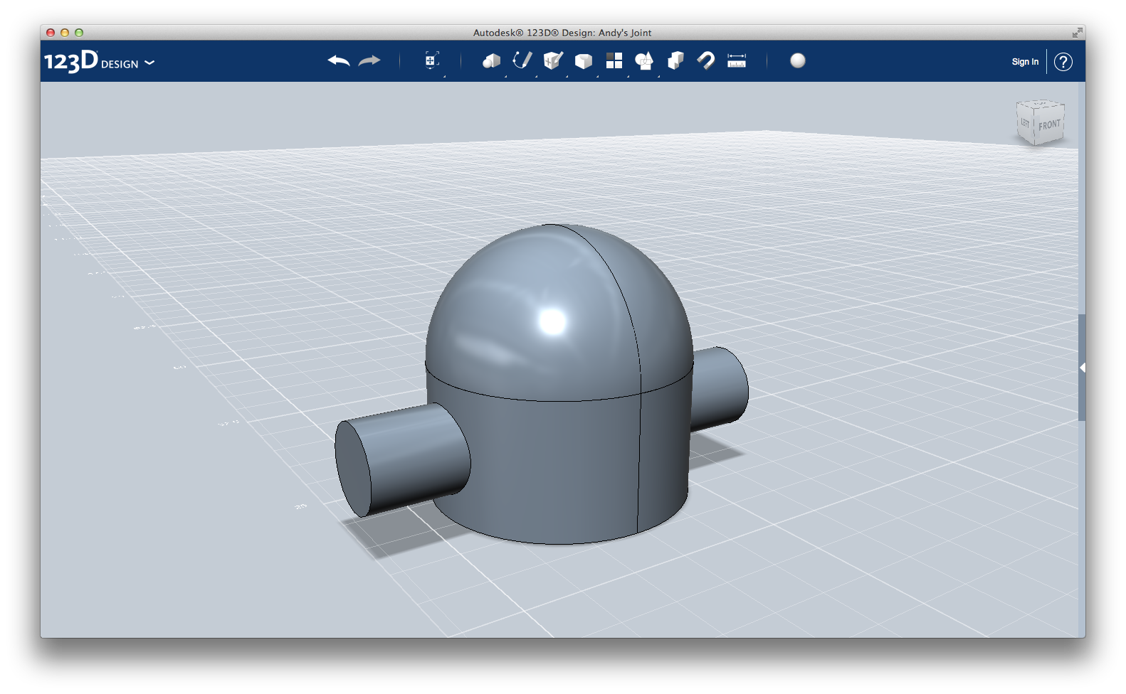
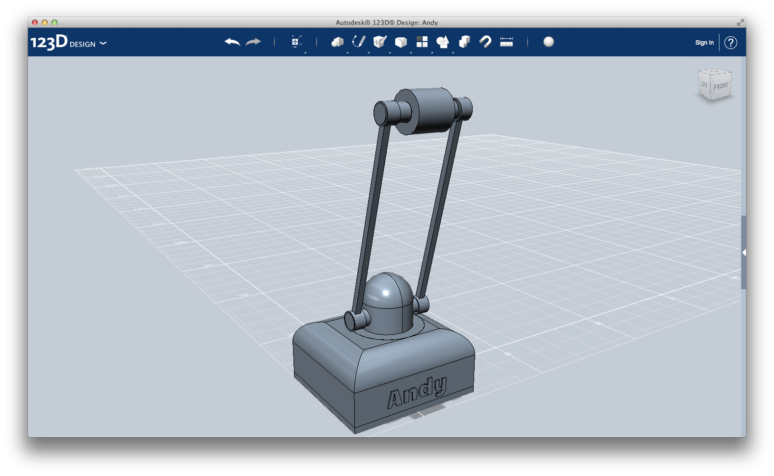
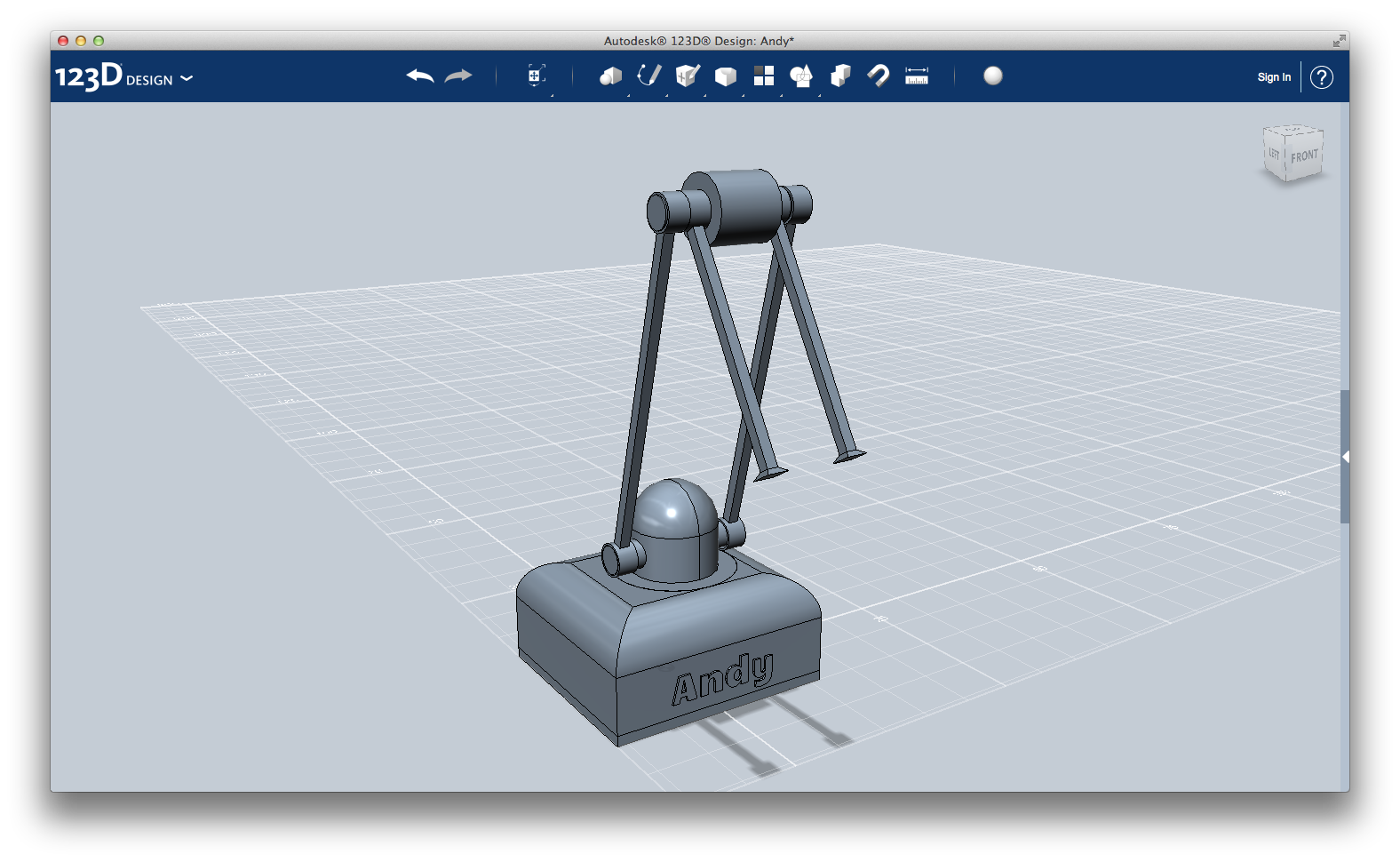
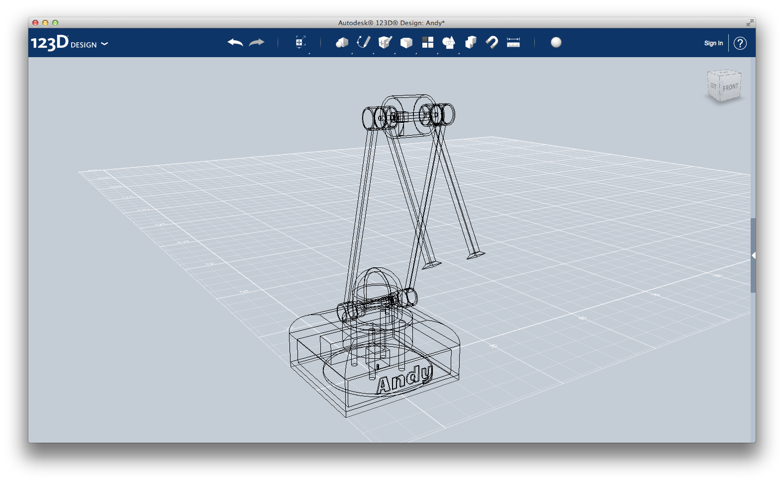
On the last three pictures, you can see Andy's base and joint together.
In next step I will show you the design of Andy's arm.
First Sub-arm
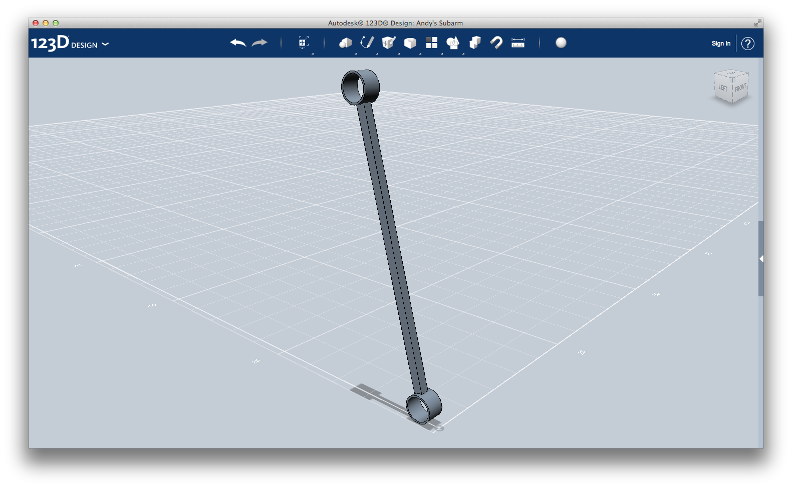
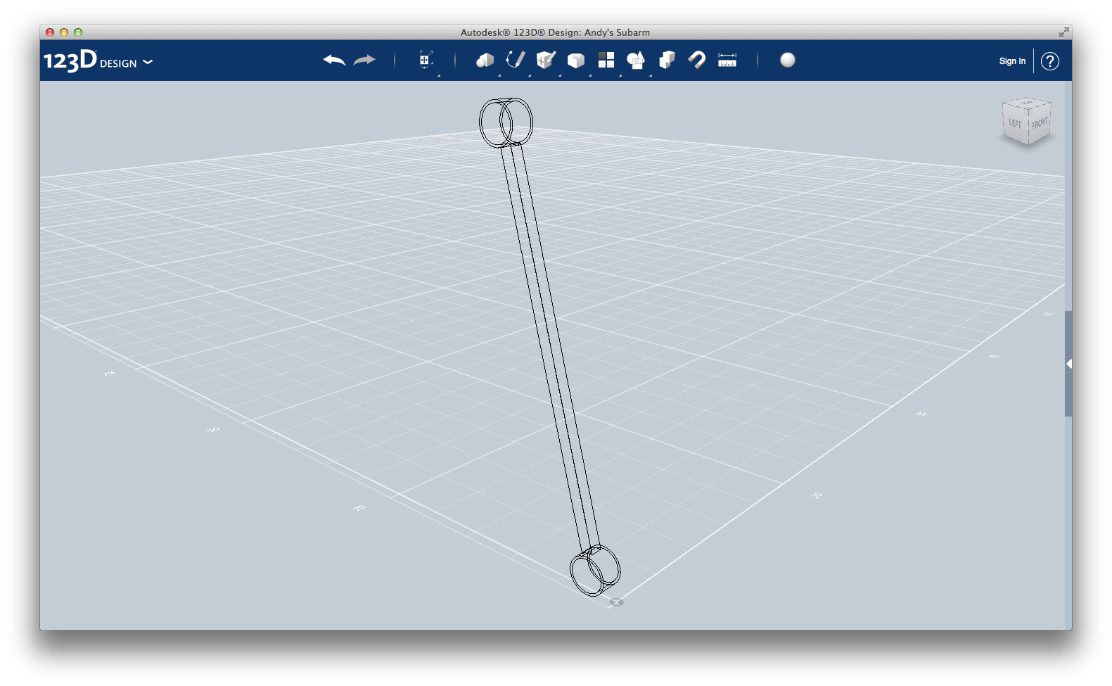
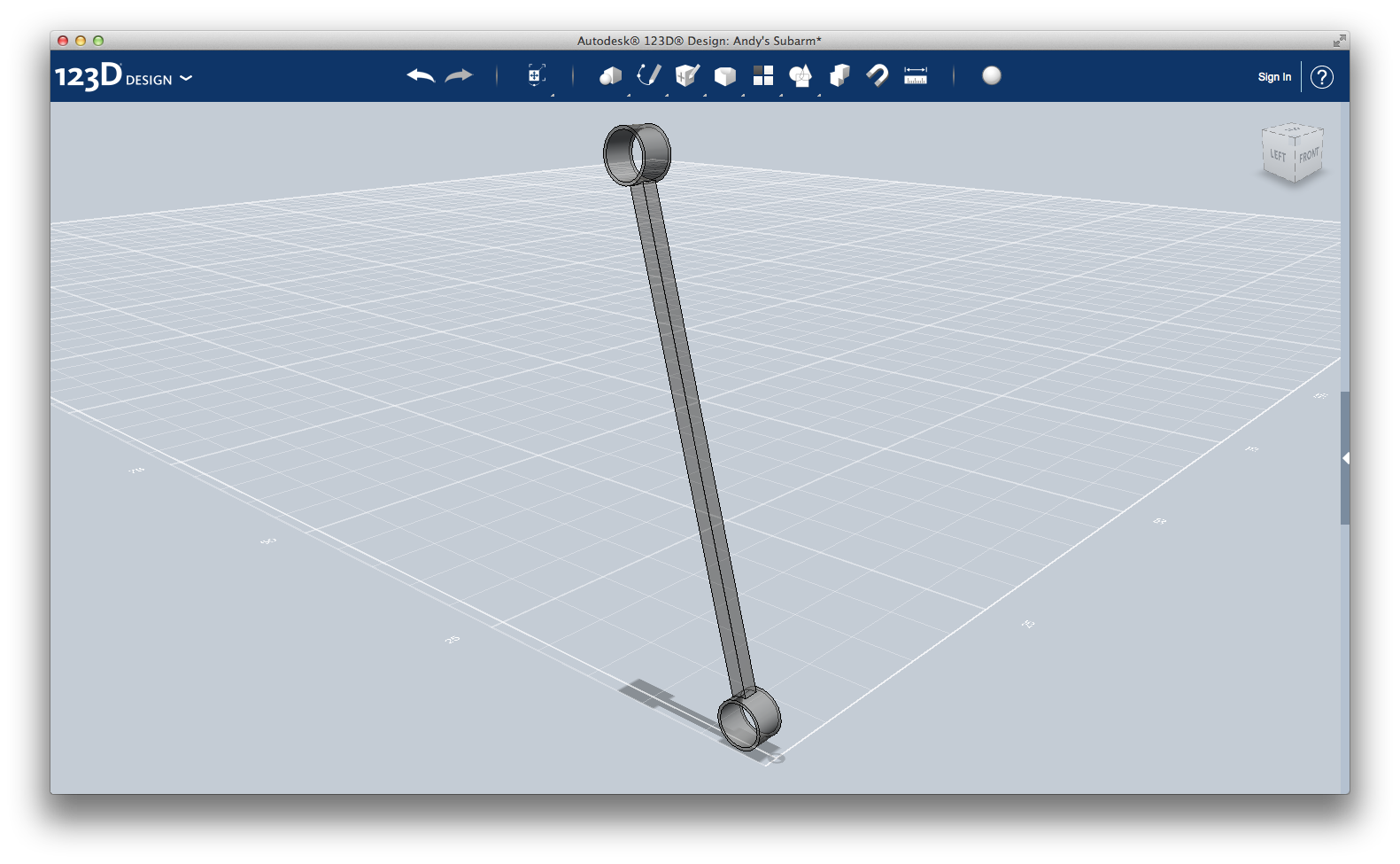
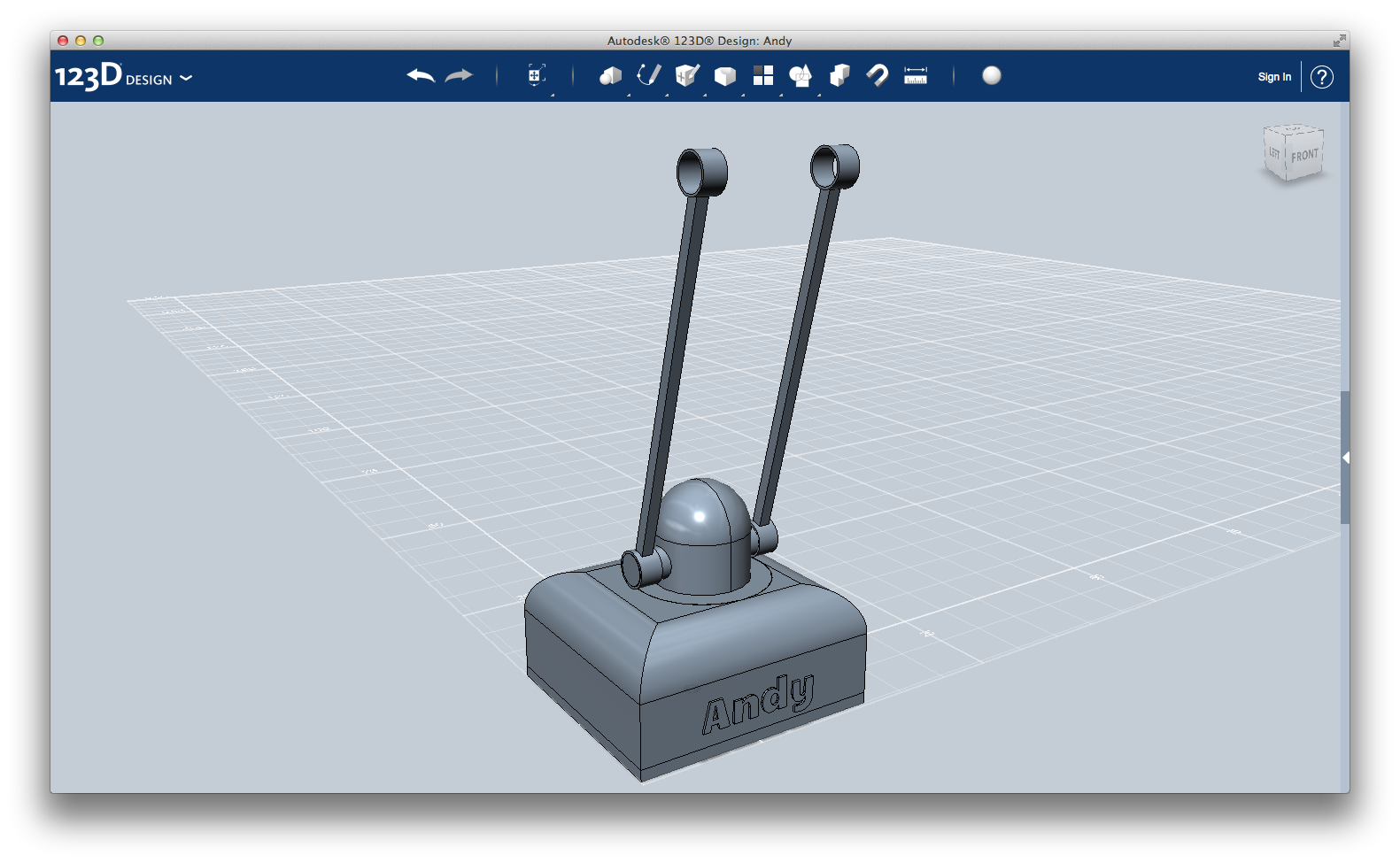
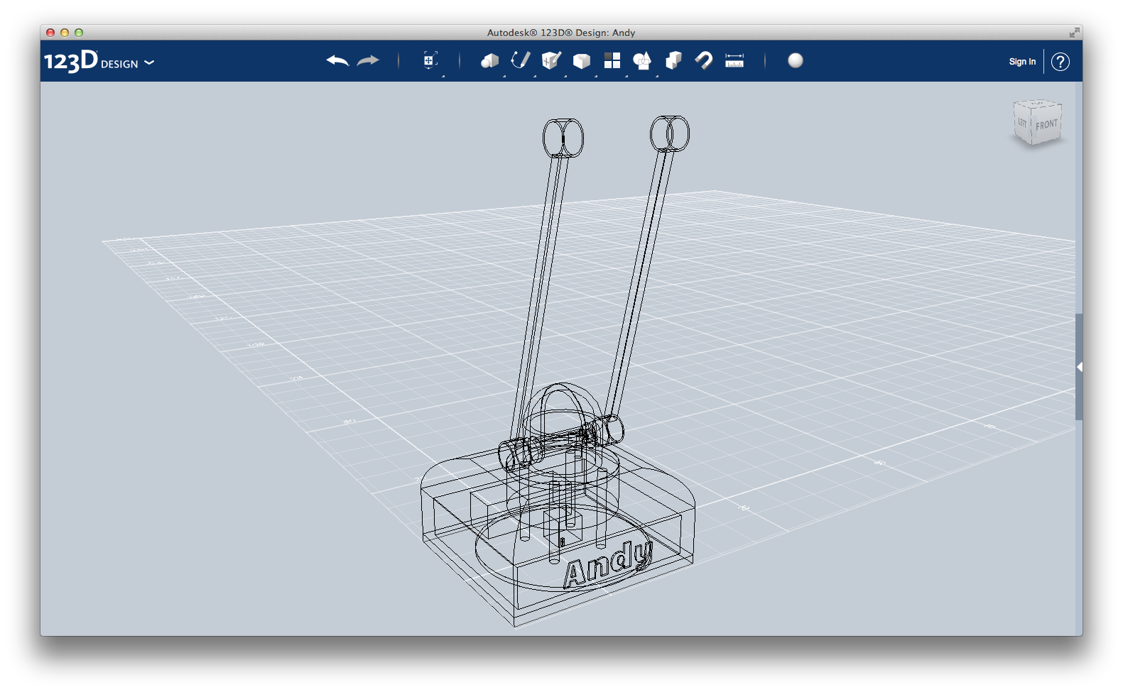
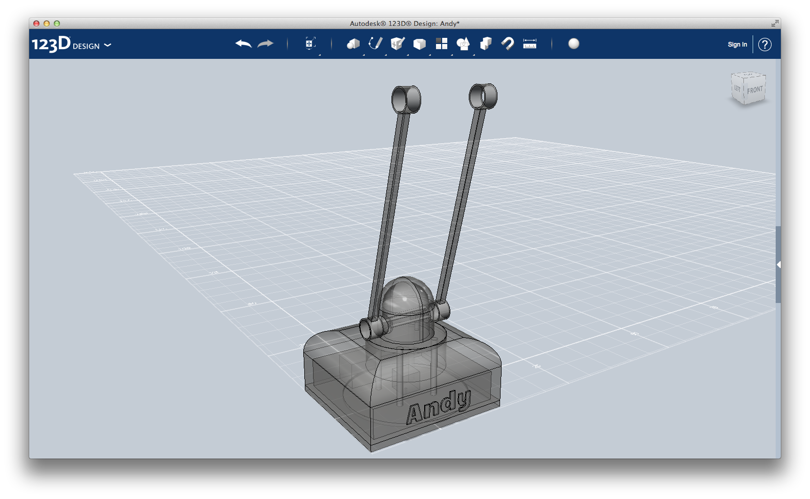
Andy's first sub-arm structure is really simple, as you can see on the picture.
Create a cylinder with radius 1.60 and height 2, and rotate if of 90 degrees as you see on the picture.
Using the Sketch > Circle and Modify > Extrude > Subtract tool, empty it. The internal circle has a radius of 1.4; so the margin left is of 0.2.
Create a 1x1x30 box and place it on the top of the cylinder using the Snap tool. Using the Move tool, move it 0.1 unit downward, joining the box with the cylinder.
Do the same with another cylinder on the top of the box.
Now, select the whole thing and rotate it of 15 degrees.
This sub-arm is ready!
You can now assemble the base and the first joint and arm all together.
In the next step I show the design of the second joint.
Second Joint
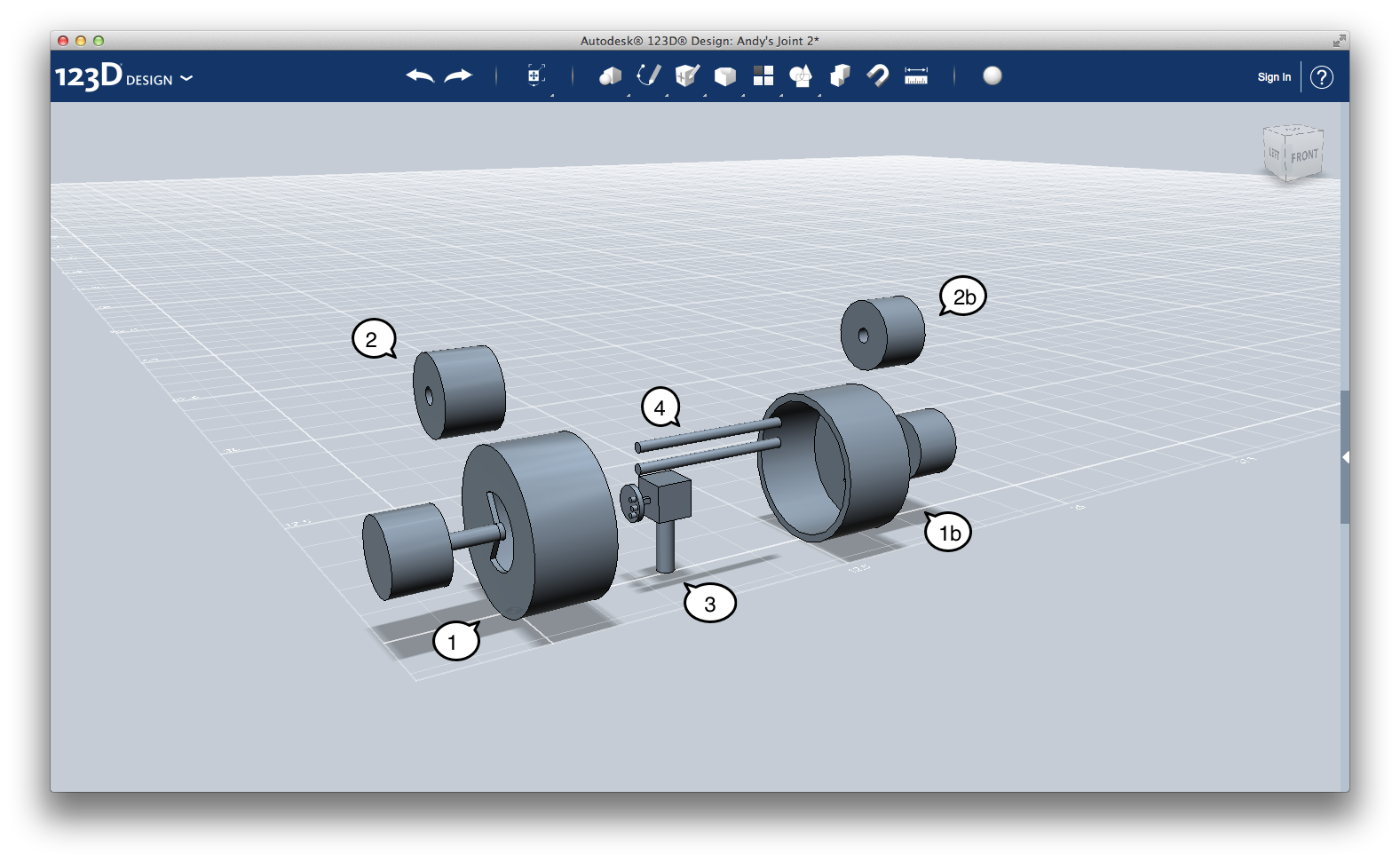
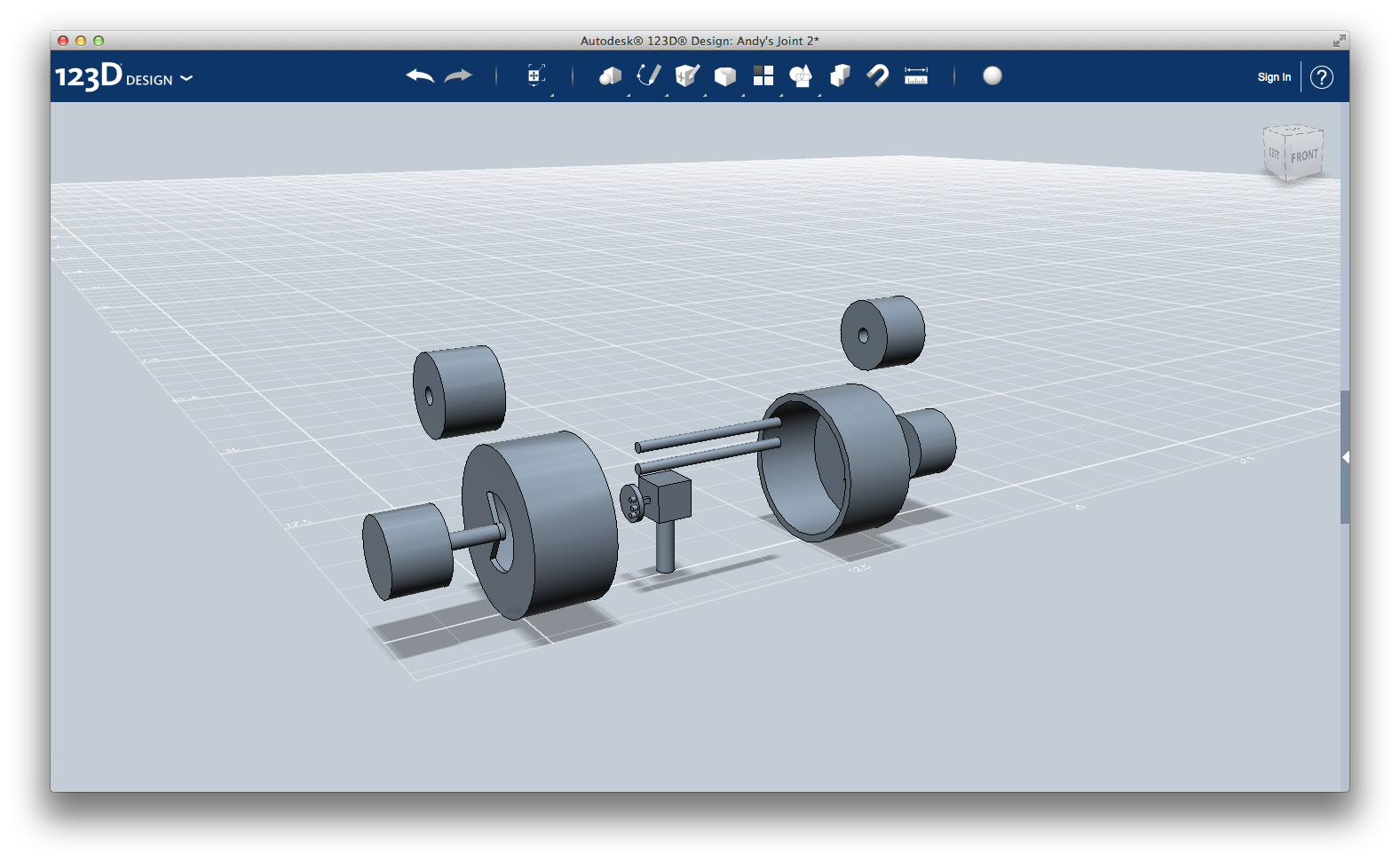
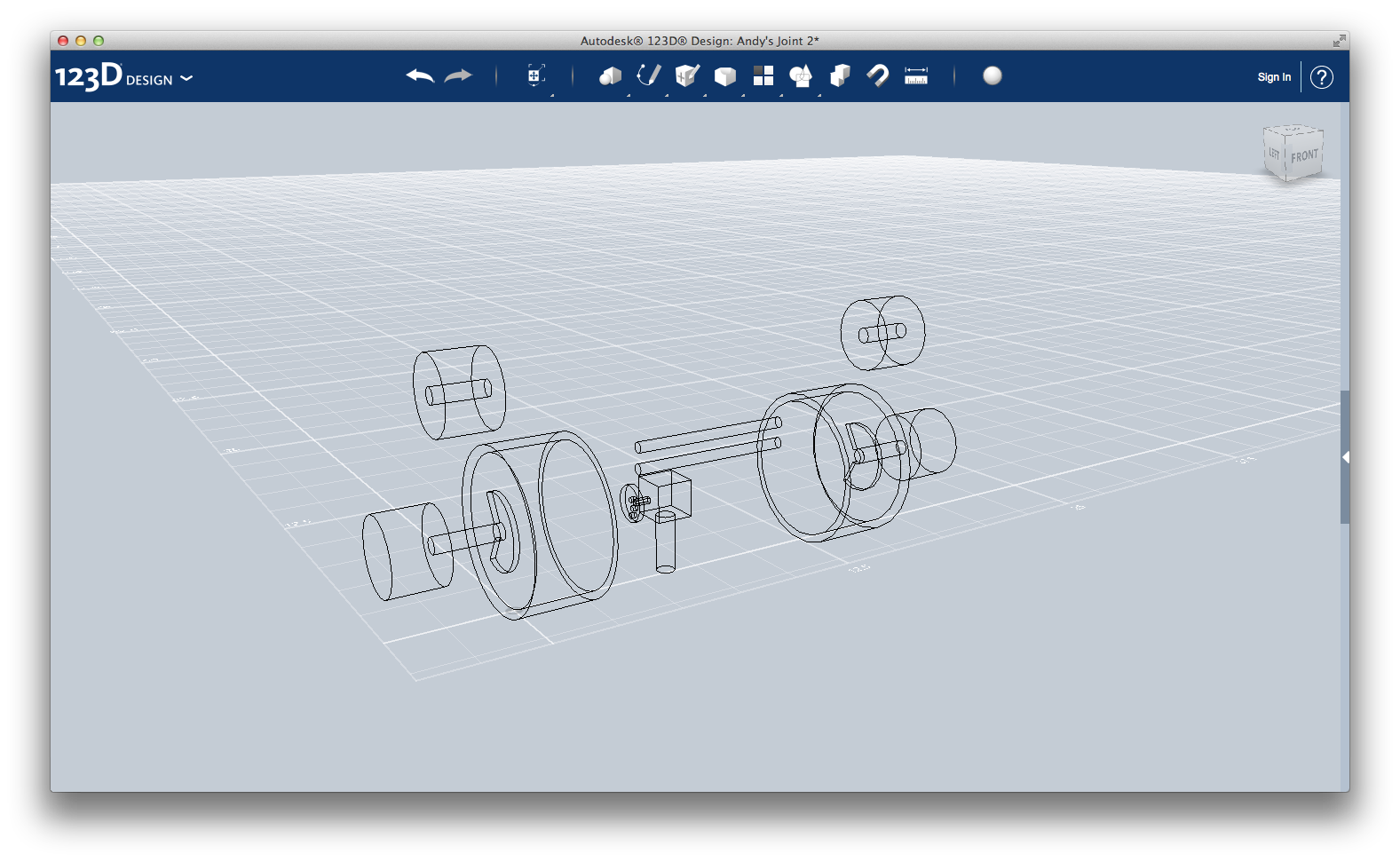
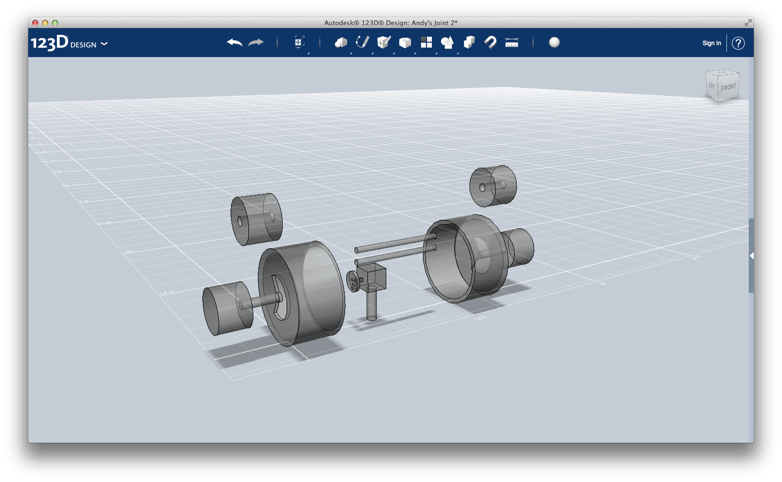
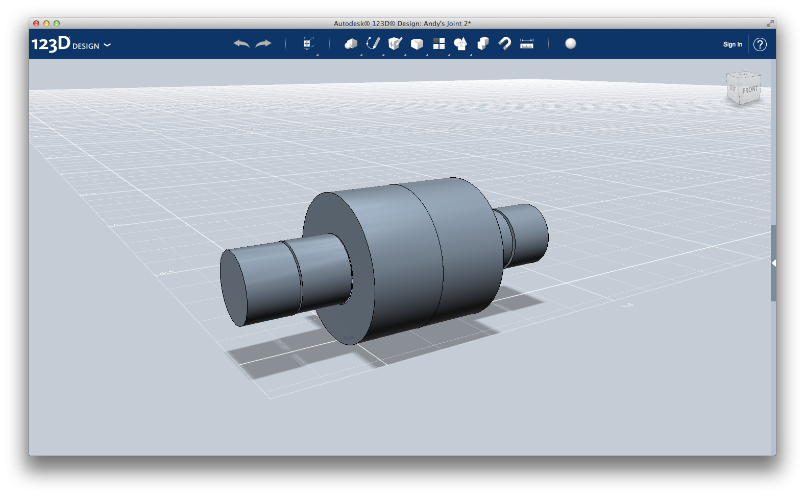
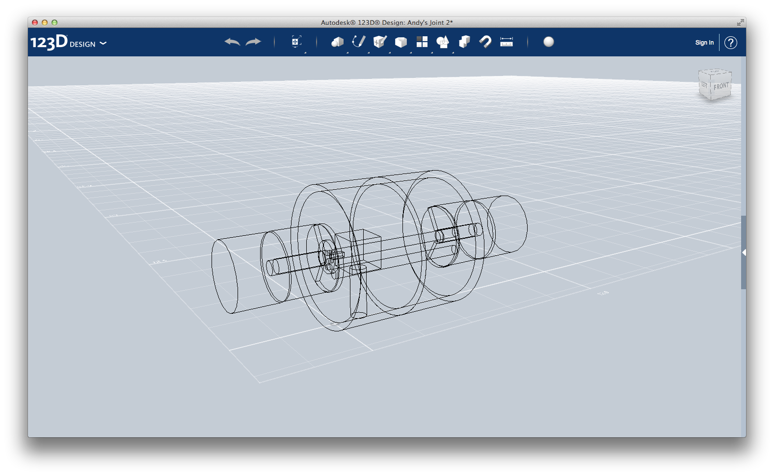
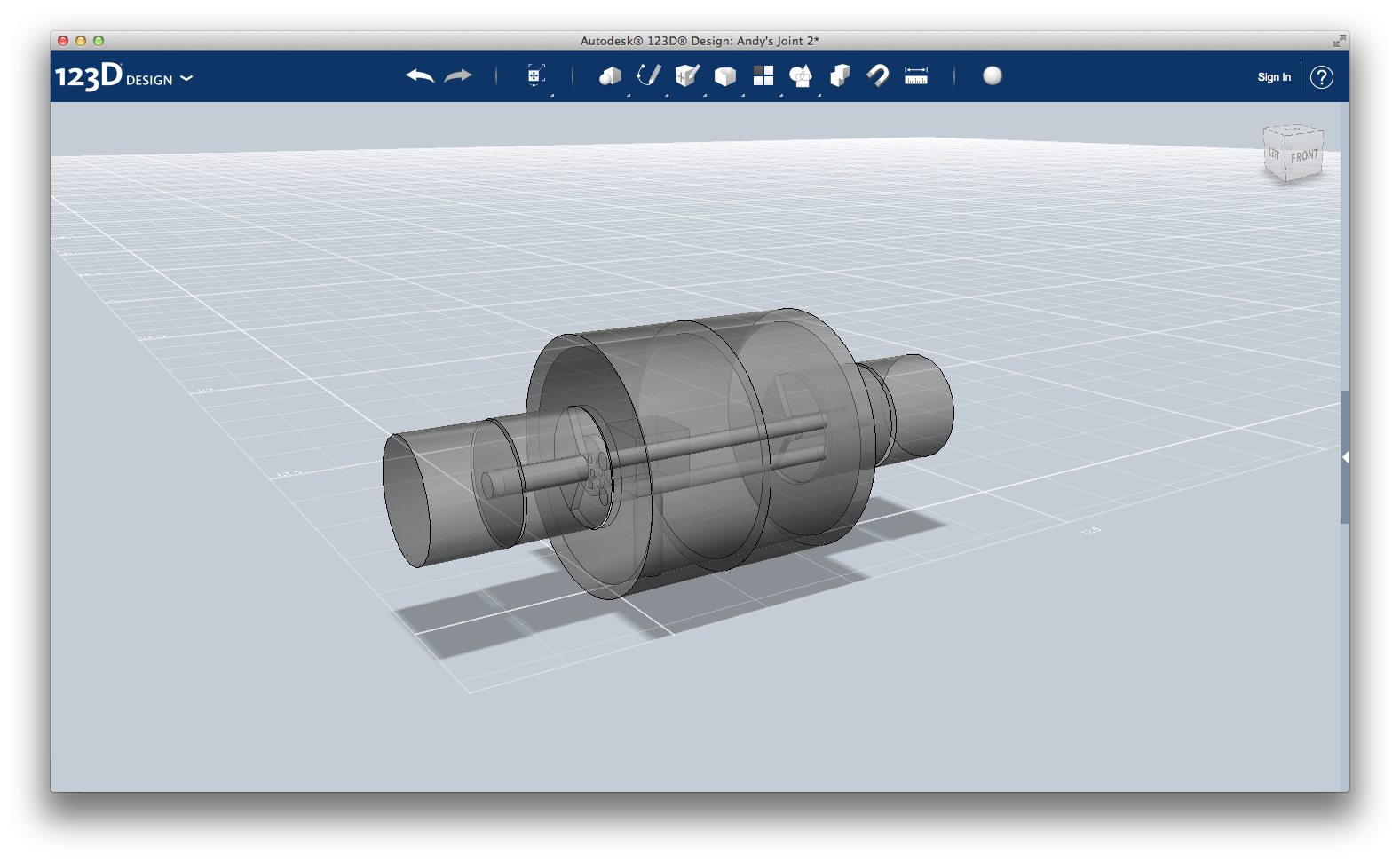
This is the second joint, the one that acts like human's elbow. It joins first and second sub-arm.
It is quite similar to the first joint, and has a servo motor that rotate the second sub-arm.
Here the steps to recreate the design:
1) This is the most difficult part, so pay attention. First, create a cylinder with radius 3 and height 3; then, starting from one base, empty it with Extrude > Subtract tool (you can use a sketch or another cylinder, as you want) leaving a margin of 0.3 on the other three faces.
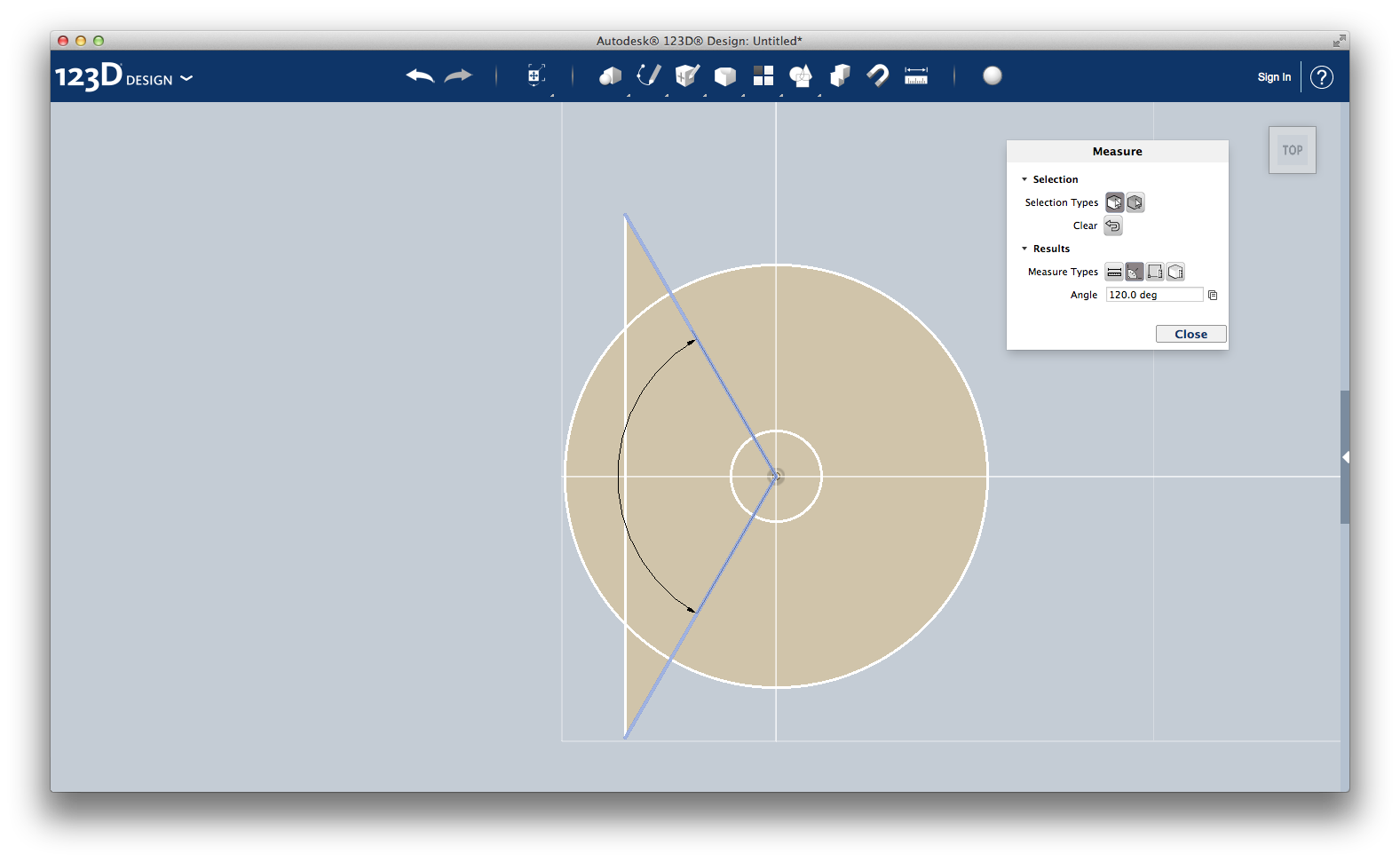
On the untouched base, using the Sketch tool, recreate the pattern as in the second picture. Draw a circle with radius 1.40. Using the Sketch > Polyline tool, draw two segments creating an angle of 120 degrees (the lines in blue). Now, select every surface on the right of the blue lines and make a hole on the cylinder face.
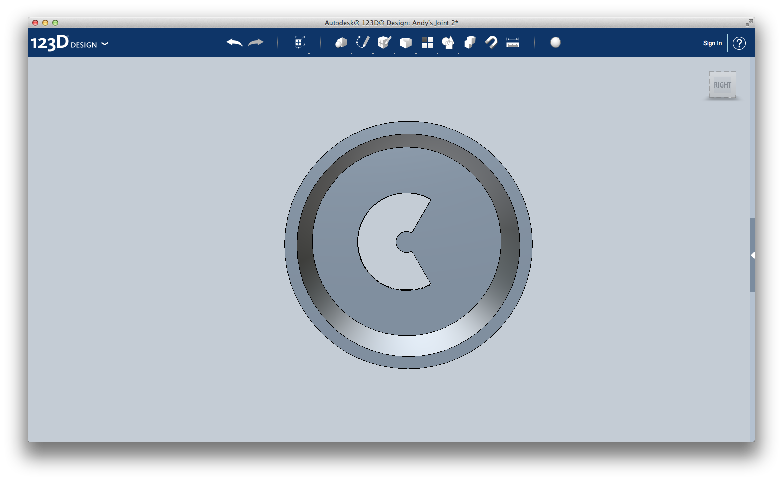
You should now have a hollow cylinder with a "C"-shaped hole on the base.
Just snap on the base a first cylinder with radius 0.3 and height 2.4 and another one with radius 1.4 and height 2.
2) Simply create a cylinder with radius 1.4 and height 2 ,and make a circular hole with radius 0.3 all over its height., and rotate it of 90 degrees as you see in the picture.
This will be placed between the two cylinders of body 1, and it is able to rotate around its axis (the middle, tight cylinder).
1 and 2 bis) Copy & paste body 1 and 2 and rotate it of 180 degrees.
3) It is the same servo motor from Step 2: "First joint". You can take it from there. However, you have to add three small cylinders (radius 0.1 and height 0.2) on the side corresponding to the body 1 cylinder's C-shaped hole. These cylinders transmit movement from servo motor to body 2 through the C-shaped hole.
4) Create two cylinders with radius 0.2 and height 6.10. They transmit the movement from body 2 to body 2bis, so connect them to bodies 1 and 2 through the C-shaped holes.
See you in next step for second sub-arm's design!
Second Sub-arm
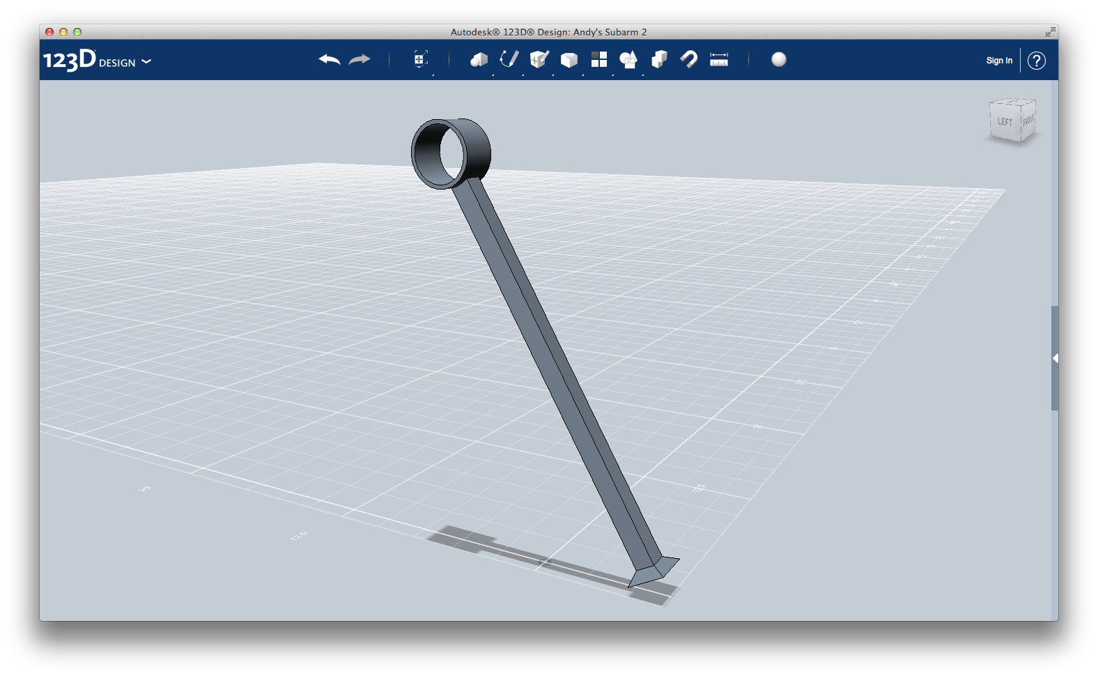
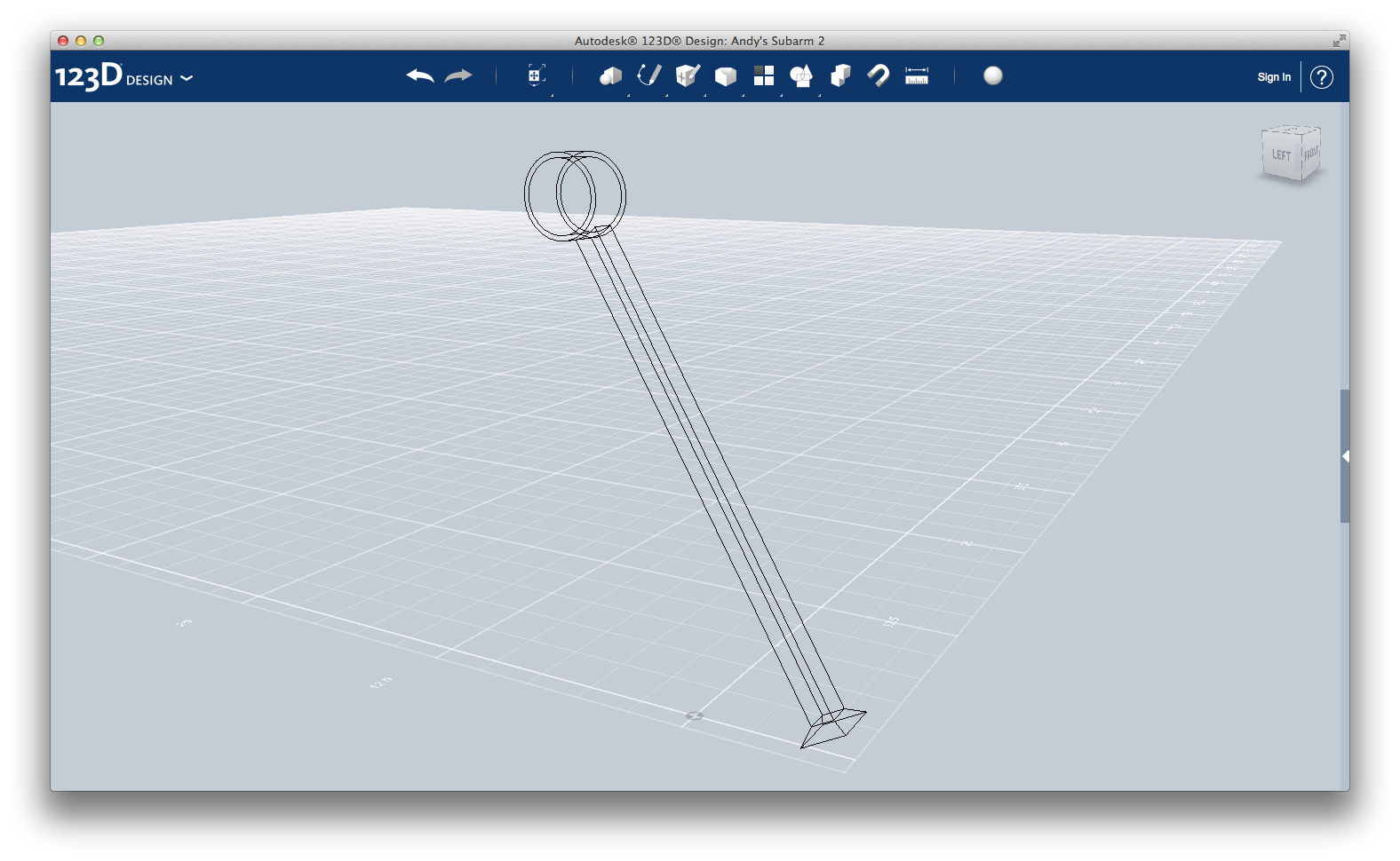
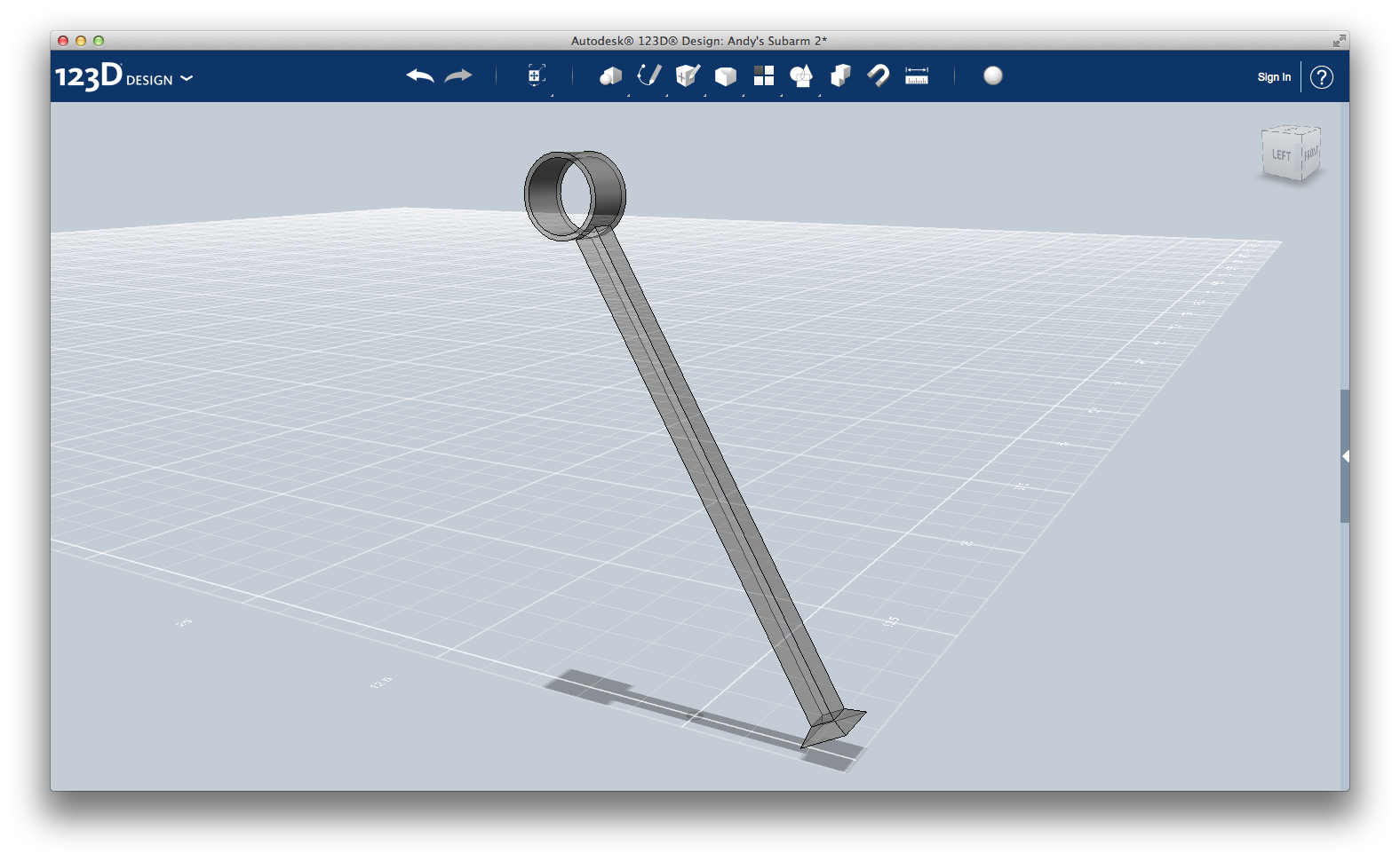
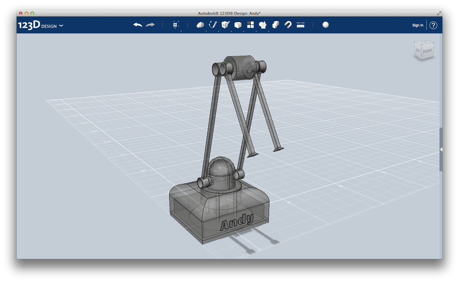
The second sub-arm is as simple as the first one. The only difference are its end (the first has a hollow cylinder, this one a truncated pyramid) and its length (overall, first and second sub-arms have the same length; but in the second one, we need to leave enough space for the claw - I will talk about it in the next step).
The procedure is identical to the one on Step 3: "First sub-arm".
The only difference is you don't need the second cylinder. Instead, create a 2x2x0.5 box. Select the four edge of the same face, and apply Modify > Chamfer tool with distance 0.5.
Attach it to the arm.
Hold on, we are almost done!
The procedure is identical to the one on Step 3: "First sub-arm".
The only difference is you don't need the second cylinder. Instead, create a 2x2x0.5 box. Select the four edge of the same face, and apply Modify > Chamfer tool with distance 0.5.
Attach it to the arm.
Hold on, we are almost done!
Claw
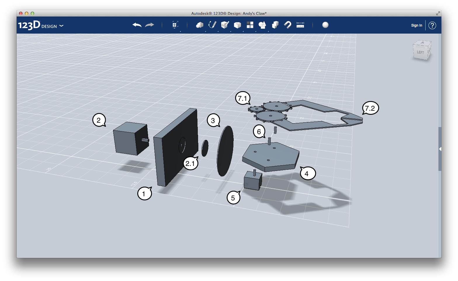
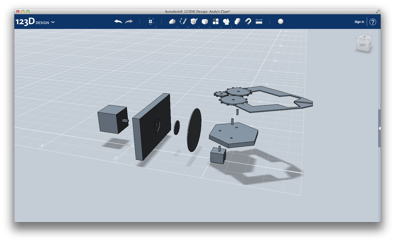
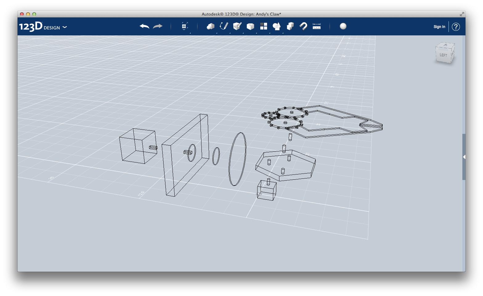
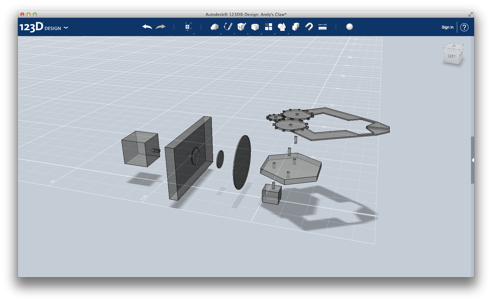
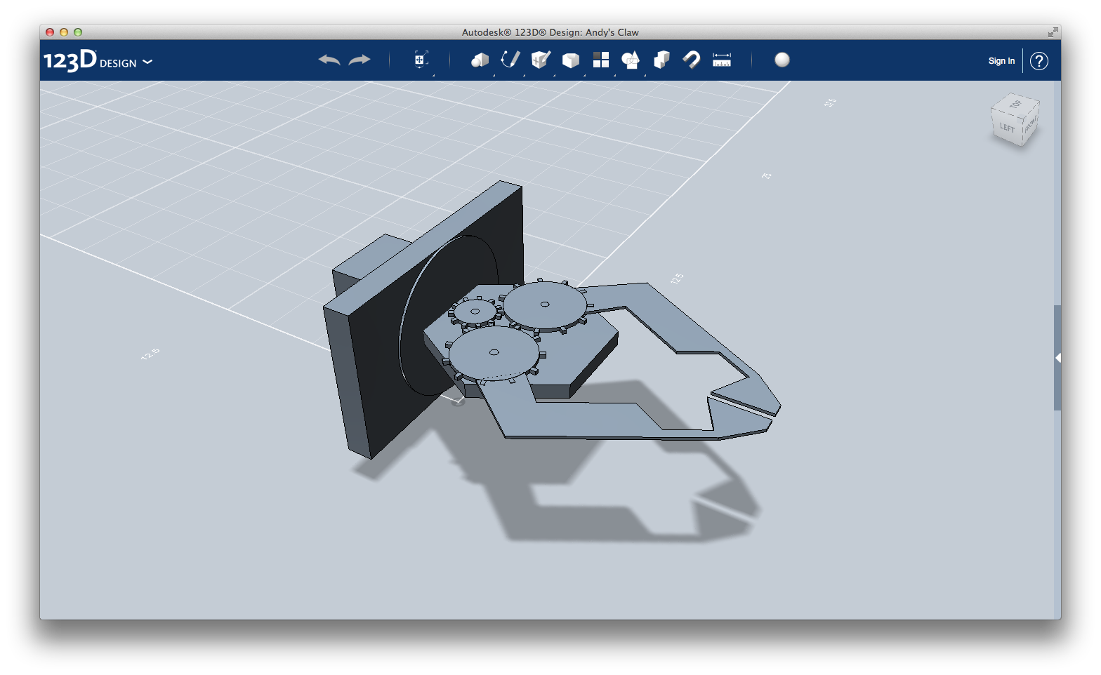
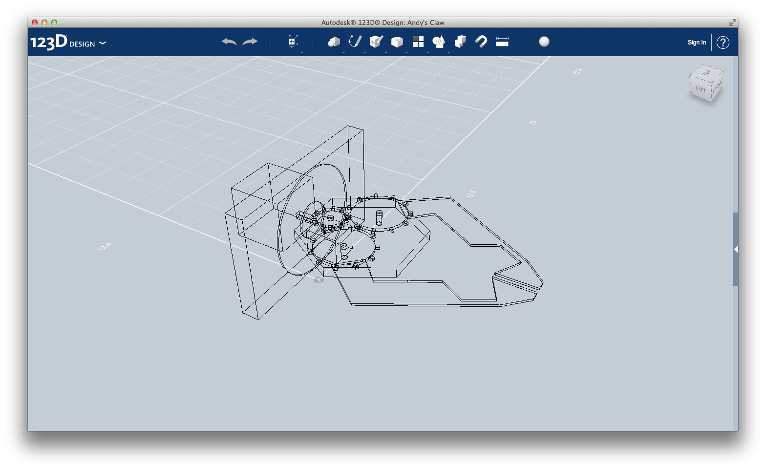
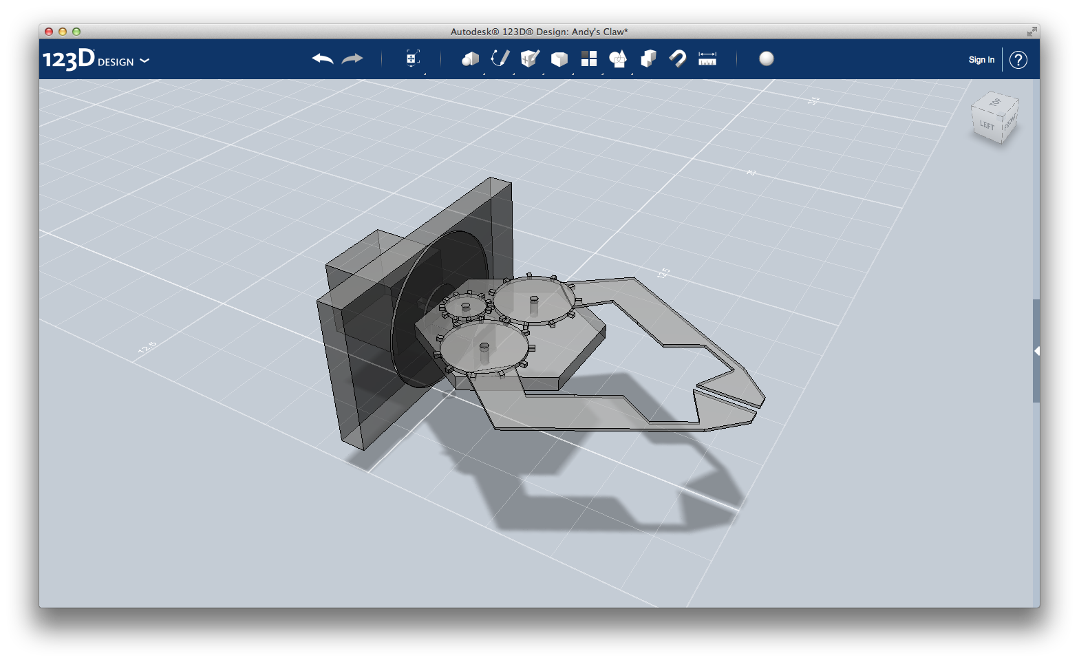
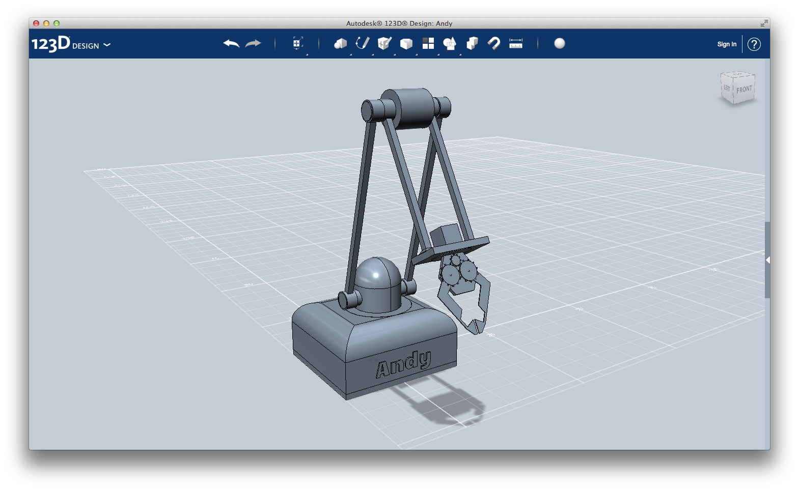
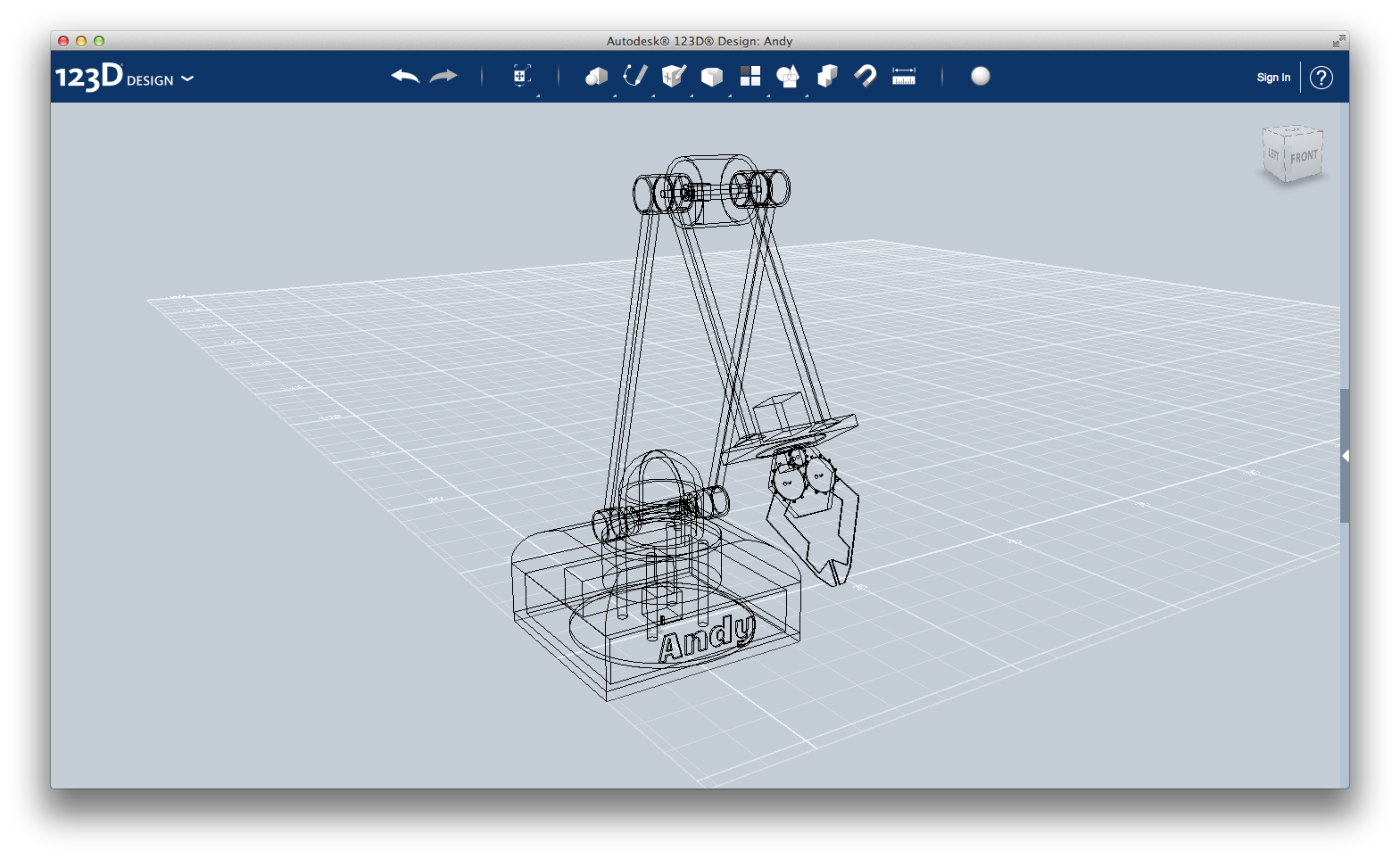
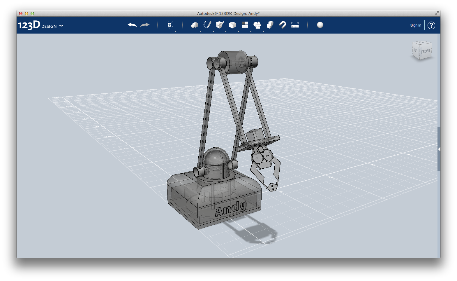
Finally, the last and most difficult part of Andy: the robot arm - the claw.
The claw can rotate and open at every angle, in order to reach everything you want.
Let's start immediately.
1) This is the body connected to Andy's second sub-arm. Create a 1x10x6 box and make a rectangular hole (size 0.3x0.3) all over its lenght. Make a second hole, a circle with radius 1 and height 0.1.
2) This is the motor that rotate the claw. It's the same of Step 1: "The base". You can take it from there.
2.1) This disk transmit the movement from the motor. Create a cylinder with radius 1 and height 0.1. Place it in the circular hole of body 1 and connect it to the motor (body 2) pin.
3) Another, bigger, transmission disk. Create a cylinder with radius 3 and height 0.1.
4) This is the claw base. Using the Sketch > Polyline tool draw a regular hexagon with side 3.5 (reminder from school: every side is equal to each other, and every side forms an angle of 120 degrees). Using the Create > Extrude > New solid tool, create the solid with height 0.6.
Make three cylindrical holes (radius 0.15) for all over its height.
Their position from the center are:
- first one: 1.90 units upward
- second one: 1.65 units leftward
- third one: 1.65 units rightward
5) The motor that opens and closes the claw. It's the same of Step 2: "The first joint". You can take if from there. Insert its pin in the upper hole of body 4.
6) These pins holds two gears. Just create two identical cylinders with radius 0.15 and height 0.75 and place them in the two lower holes of body 4.
7) Body 7 is formed by gears and pliers.
7.1) We need three gears of two different size, as you can see in the picture.
Using the Sketch > Circle tool, create a circle with radius 0.75. Create a cube with side 0.15 and place it so that the box barely touch the circle. Using the Pattern > Circular pattern tool, select the cube and the circle and create other 10 cubes. In total you should have 11 cubes.
Create > Extrude > New solid the circle with height 0.15. Make a circular hole at its center for all over its height, with radius 0.15.
Place it in corresponding of the upper hole in body 4 and pin of body 5.
Repeat the procedure using a circle base with radius 1.50 in order to create the two bigger gears.
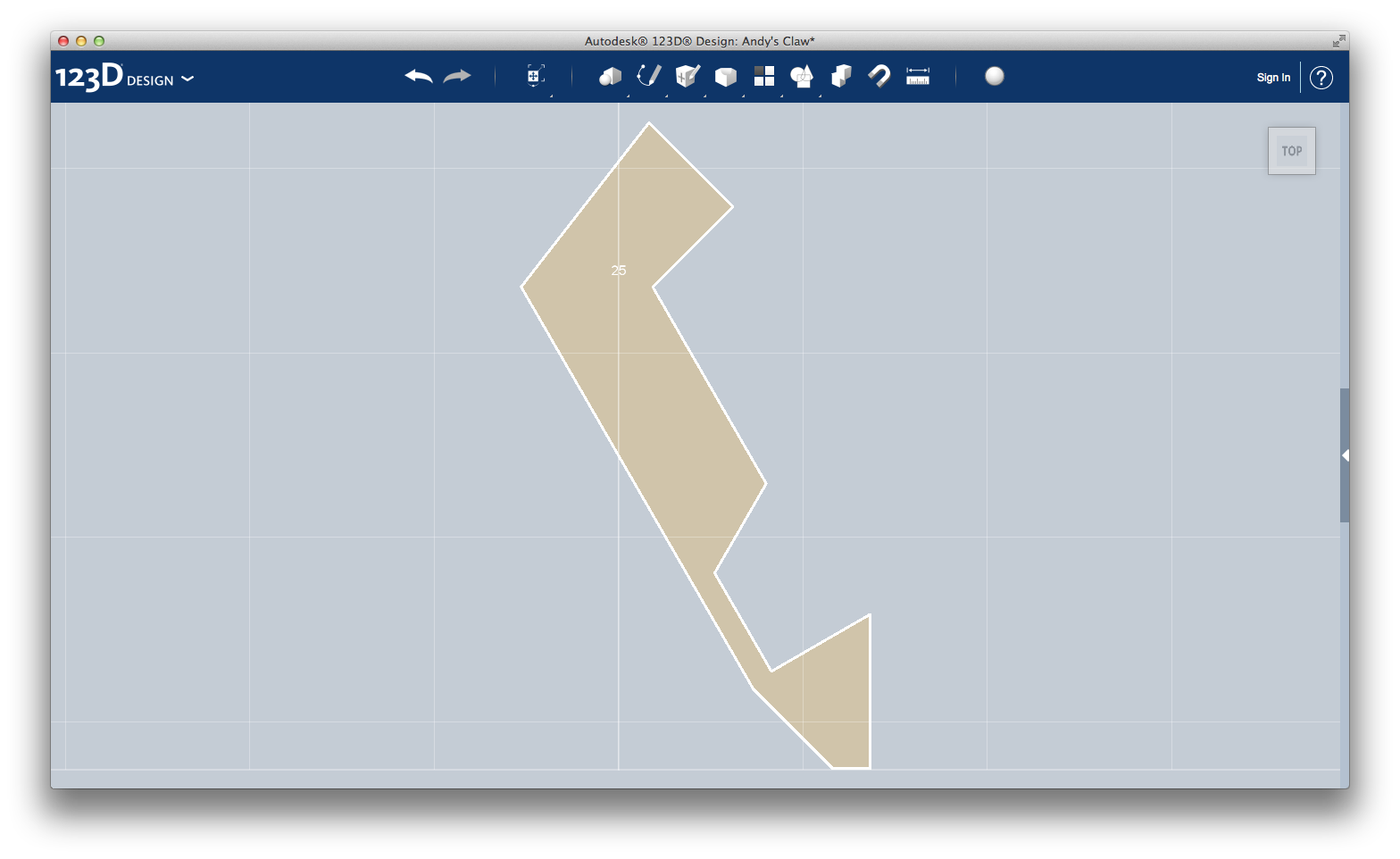
7.2) Using the Sketch > Polyline tool, create the following shape. I will tell you the lenght of every segment, and the angle that every segment make with the previous one.
Warning: the angle is ALWAYS the one inside the shape. Help you with the image of the sketch, above (it's the fifth one).
This is the procedure:
- segment 1.60 long;
- segment 1.55 long, angle of 90 degrees;
- segment 3.10 long, angle of 210 degrees;
- segment 1.40 long, angle of 120 degrees;
- segment 1.55 long, angle of 240 degrees;
- segment 1.55 long, angle of 270 degrees;
- segment 2.00 long, angle of 60 degrees;
- segment 0.50 long, angle of 90 degrees;
- segment 1.50 long, angle of 135 degrees;
- segment 6.70 long, angle of 164 degrees;
- connect the two ends together.
Now, use the tool Create > Extrude > New solid with height --- and join it with one of the biggest gears. Do the same with the other one.
Now, assembly everything together.
Congratulations, Andy's design is done!
Conclusion and Final Considerations
Here I am, at the end of this little journey. It has been really instructive: I learnt how to basically use a 3D design software and to think, sketch and design a product, turning an idea into a 3D model.
I want to analyze my work, listing good e bad sides of what I did.
Pros
- I learnt the basics of a 3D design software
- I turned a simple idea in a quite finished design
Cons
- The model cannot be 3D-printed as it is: you should print each component separately and then assembly them
- Motors' size in the model are totally invented. I did not measure a real-life motor.
- I don't know if the base is strong and stable enough to hold up the arm, or if the motors are strong enough to move it.
- The claw is probably too much slight, and I don't know if it is strong enough to pick up and move around an object.
- I did not think about wiring: every motor needs to be connected to the Arduino chip in the base.
- I also did not think about how to combine together the various component, if and when use screws or glue or something else.
As you can see, the cons list is much longer than pros list. However, I am proud of my work and conscious that it has been a great step for my growth in the world of makers and, why not, of work.
Please, feel free to express your opinion. Congratulations are welcomed, as well as constructive criticisms. Indeed, the second ones are a lot more useful!
If you like Andy and my work, please vote me for Autodesk 123D Design Challenge. Thank you!