Android + Arduino Labyrith Game
by Madrajib in Circuits > Arduino
12048 Views, 89 Favorites, 0 Comments
Android + Arduino Labyrith Game
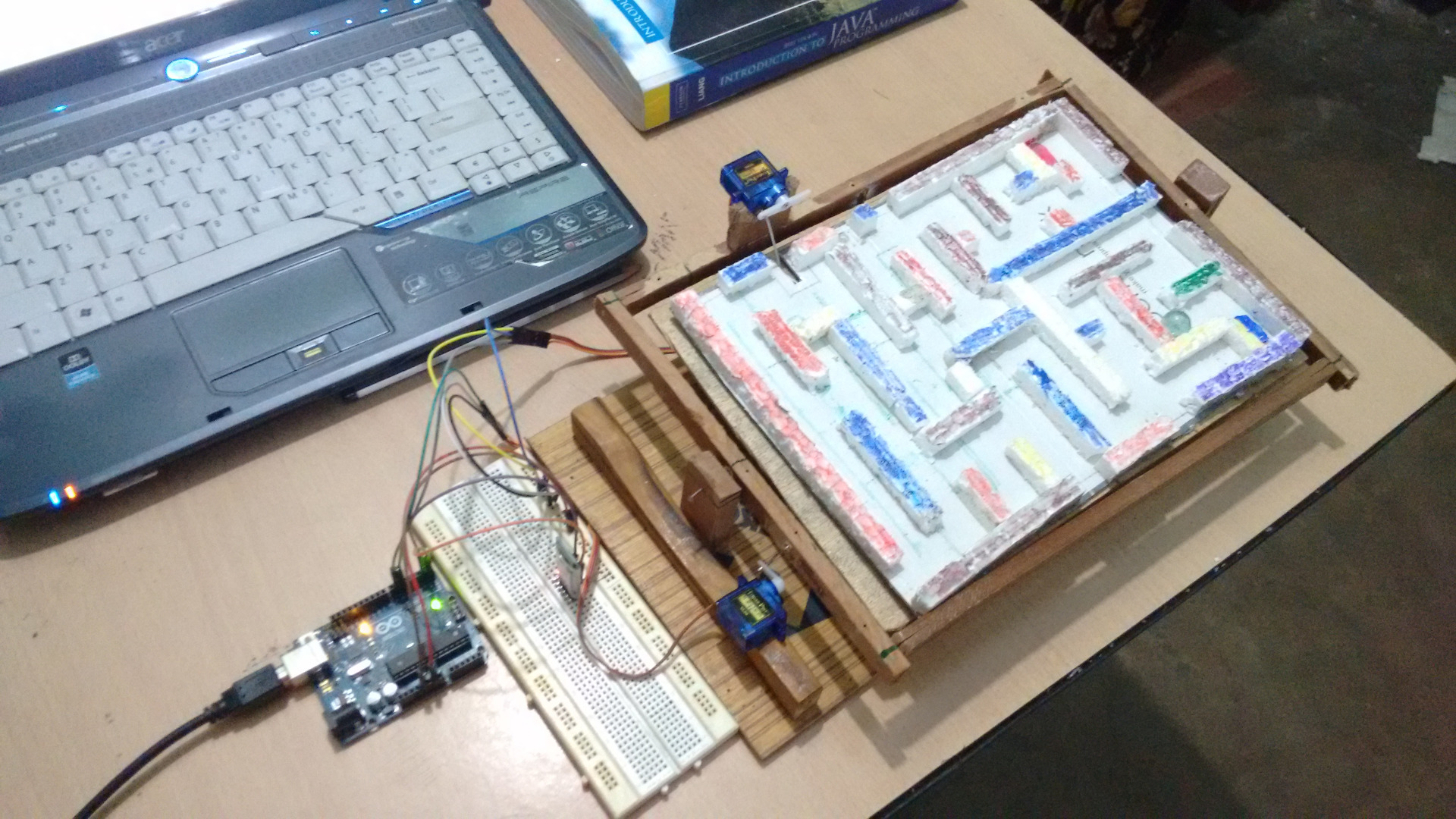
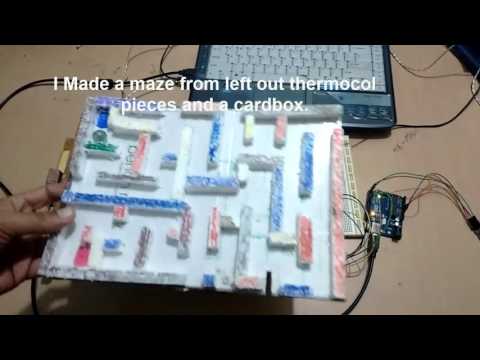
Hie guys ..
Have you ever wandered to make a labyrinth Board which can be controlled From Your Android Smartphone ....!
Well you are in the right place . I built one for myself using Arduino and android .
Don"t worry its easy ,.. In this project i will show you how to make:
1. Labyrinth Board (i made it from old wooden boxes laying around).
2. Android app in app inventor for controlling the board.
3. Writing the program in Arduino for controlling the Board and
4. Setting up the circuit ....
You can later use the concept learned in other projects that you will build..
So without wasting any more time, lets start....!
Gathering the Components.

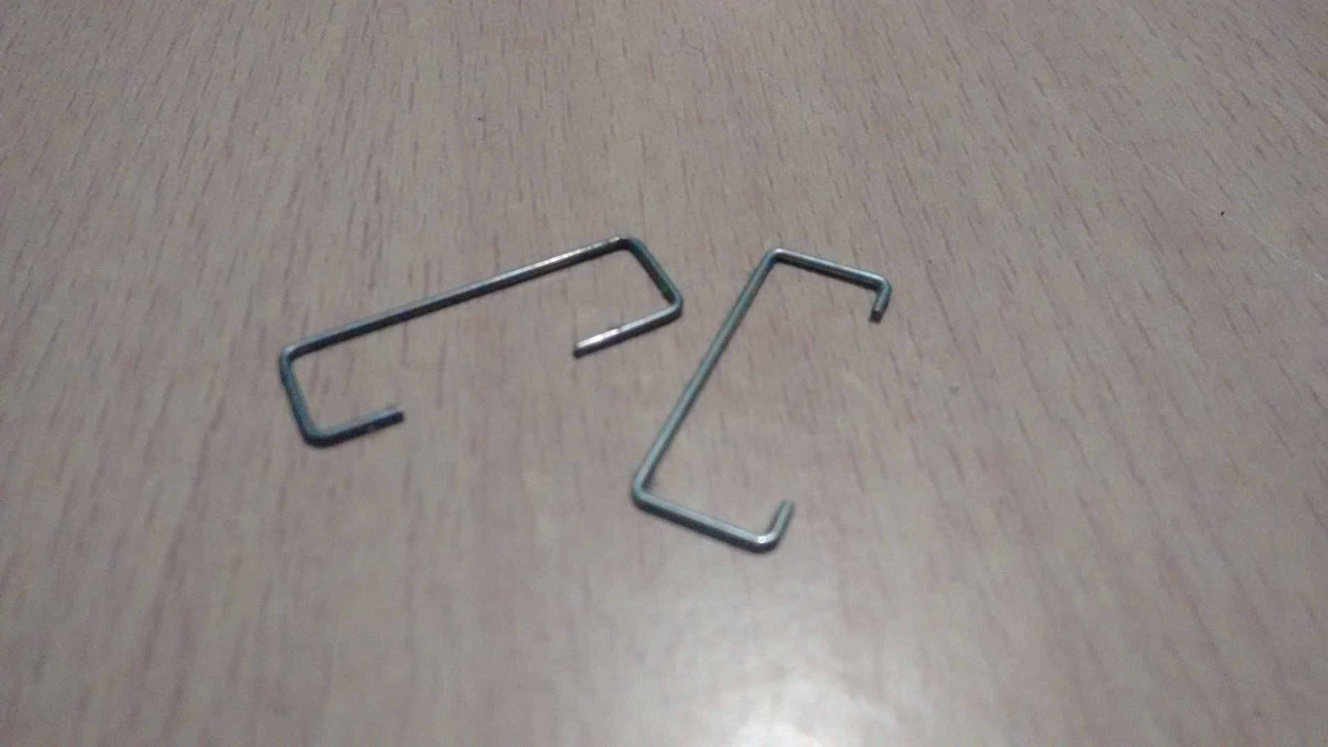
For this project you will require the following items:
1.Two servo motors (i used mini ones and they worked for me).
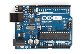
2. Arduino Uno.( I suggest buying it from snapdeal, its a clone but is worth of every penny i spent)
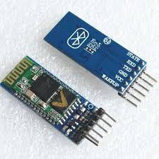
3. A Bluetooth module .
4. A Breadboard.
5. Some jumper wires
6. Thin wooden or hard boards
7. nails , some key rods from old keyboards
8. Thermocol (Polystyrene)
Making the Labyrinth Board
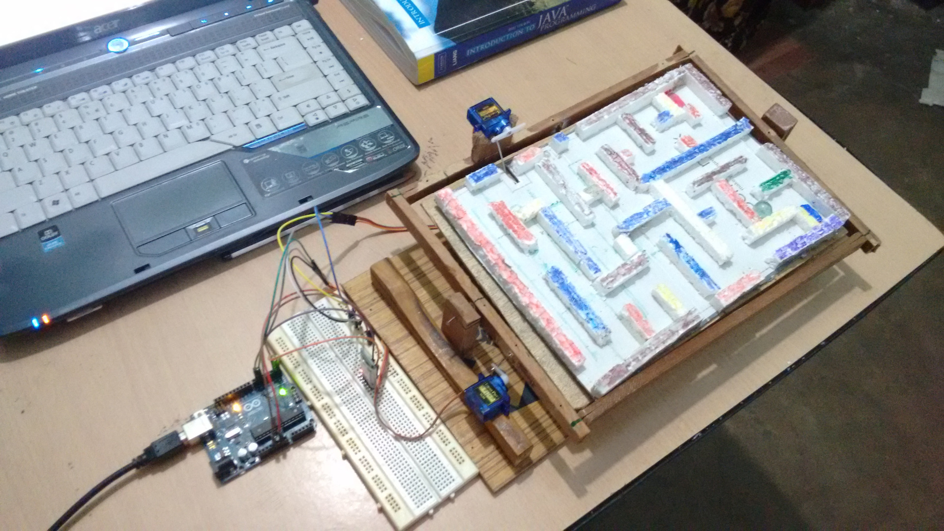
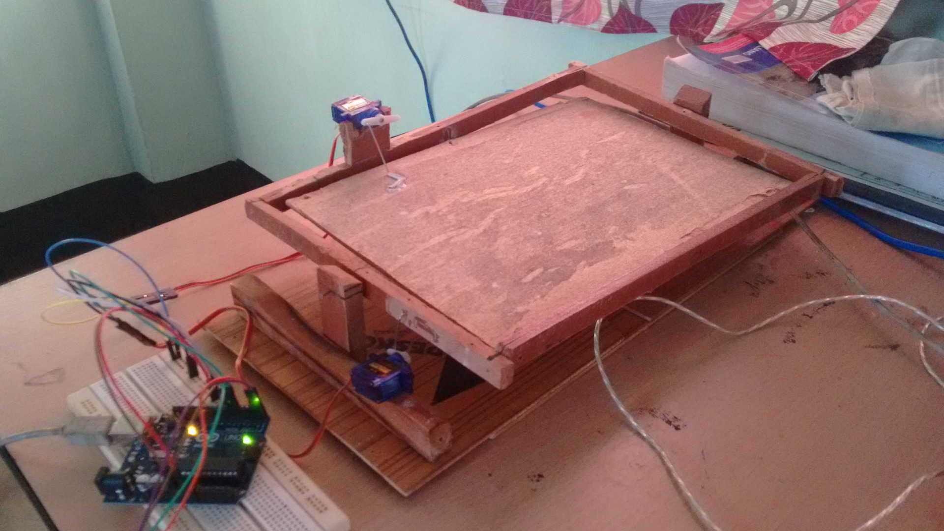
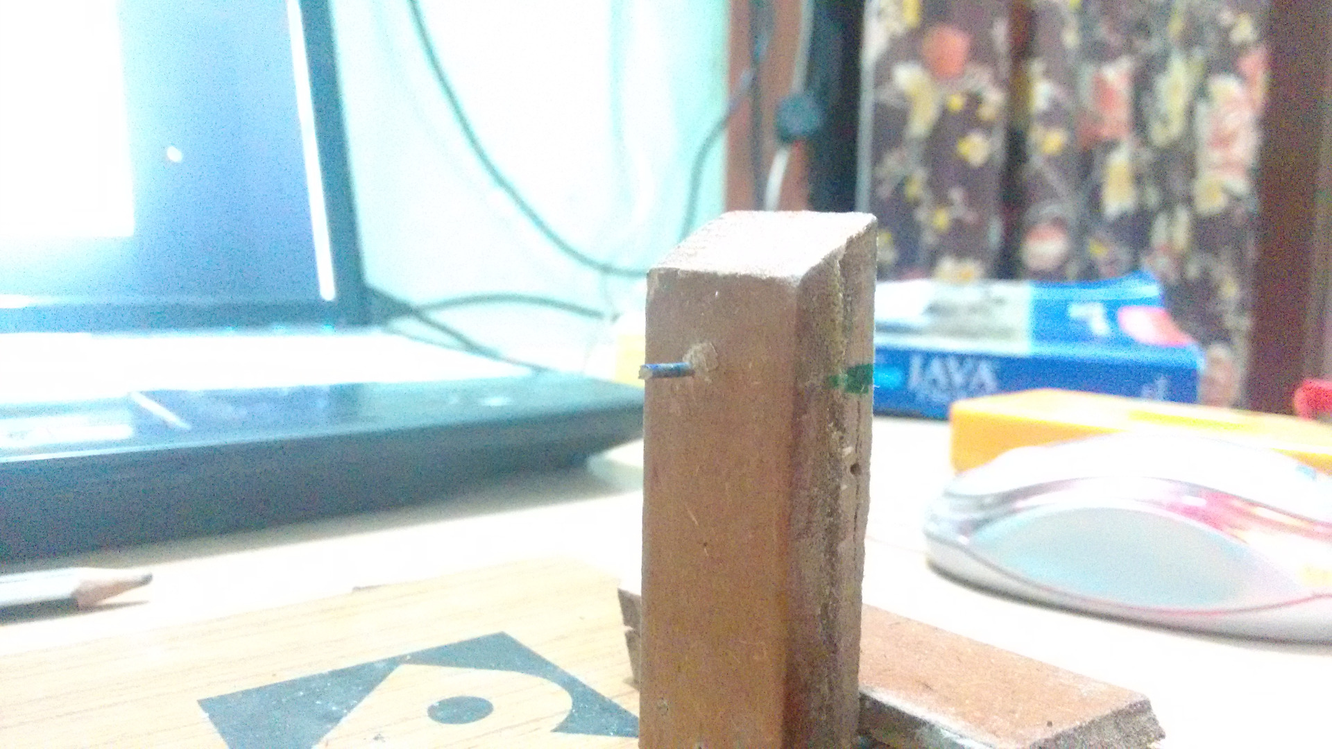
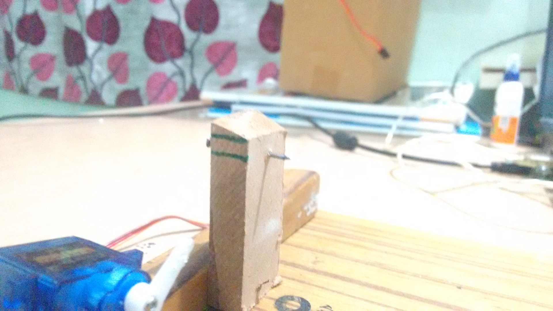
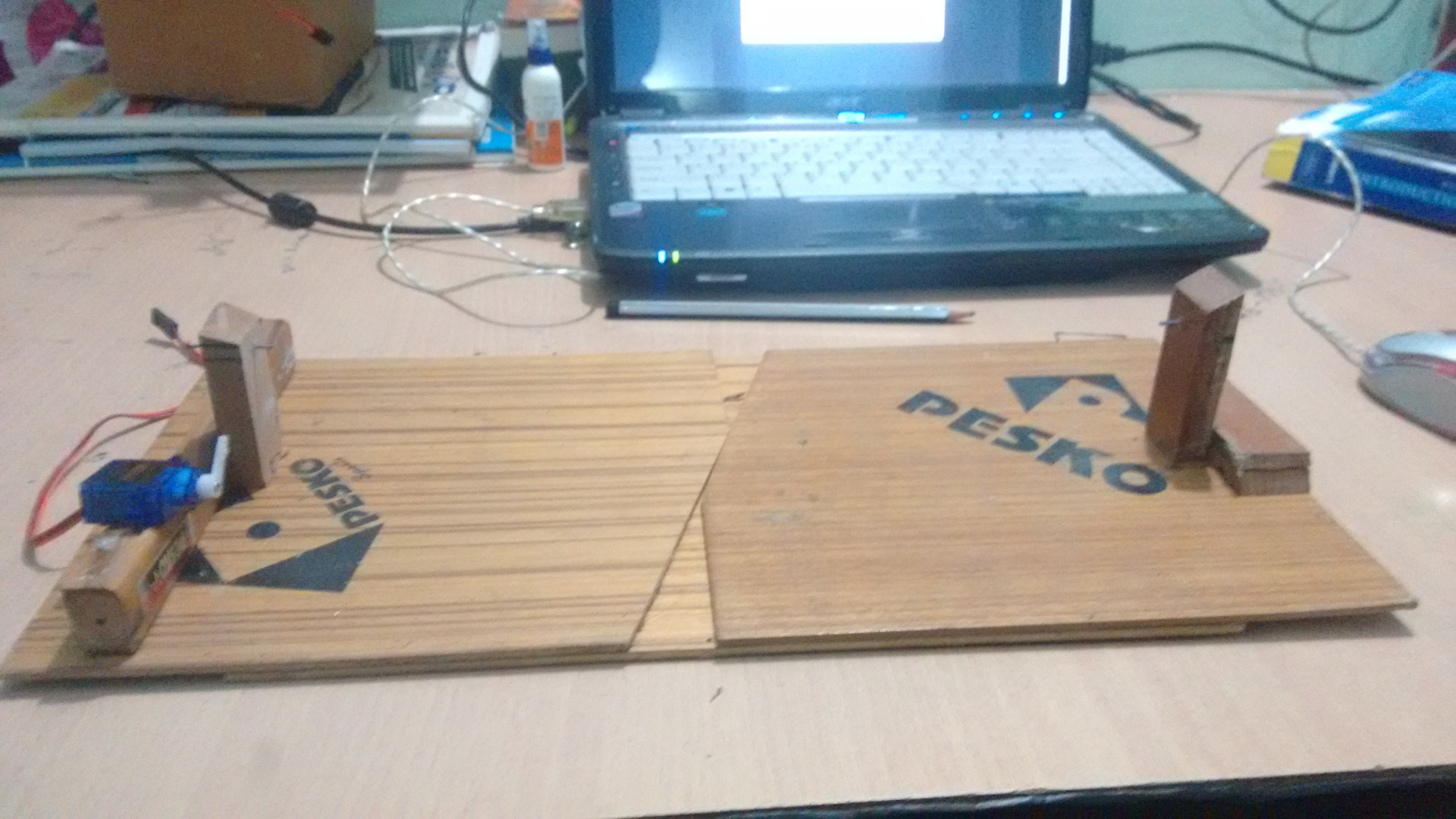
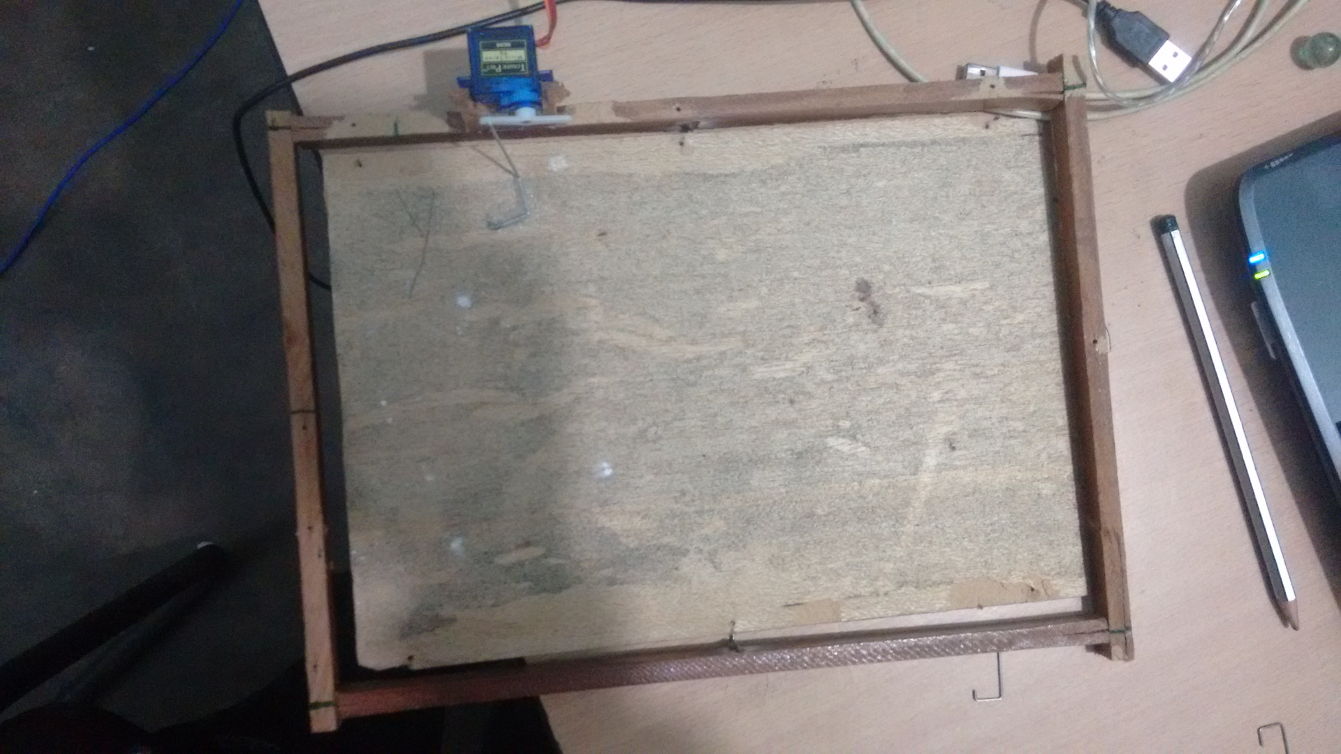
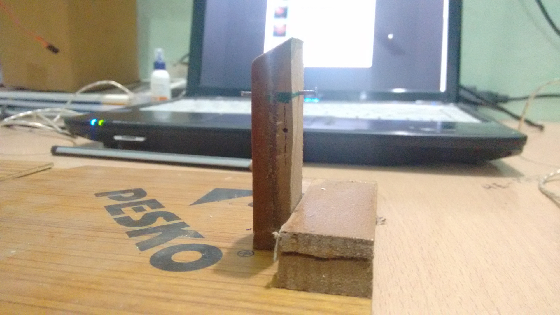
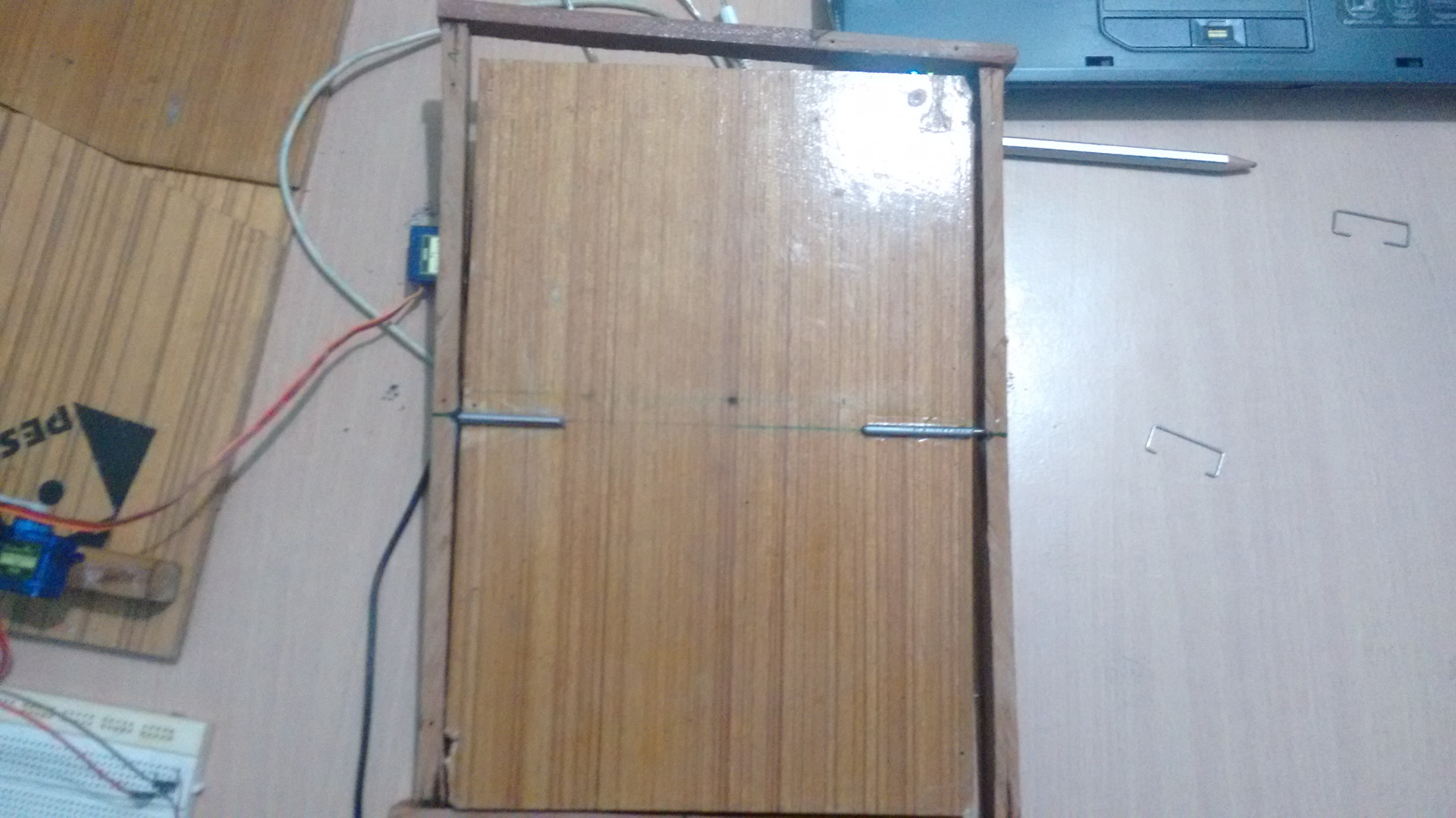
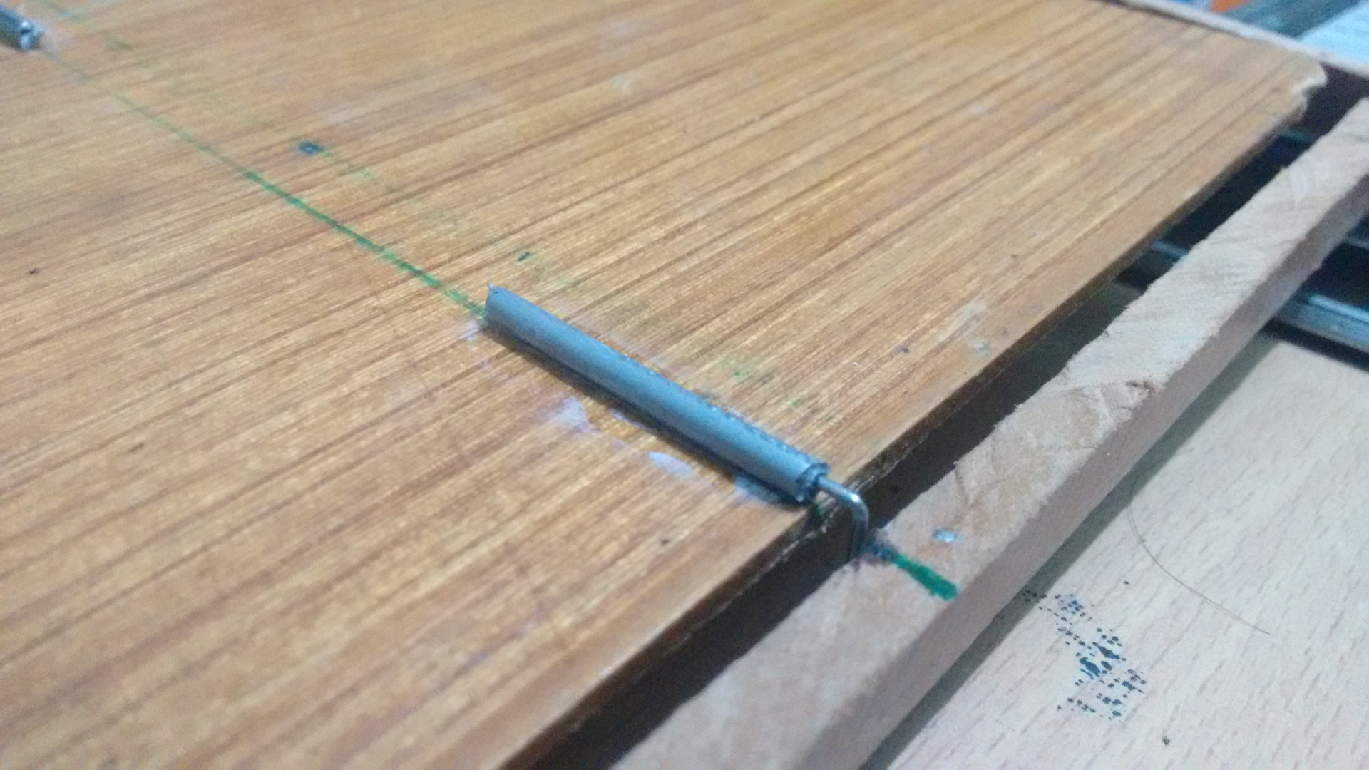
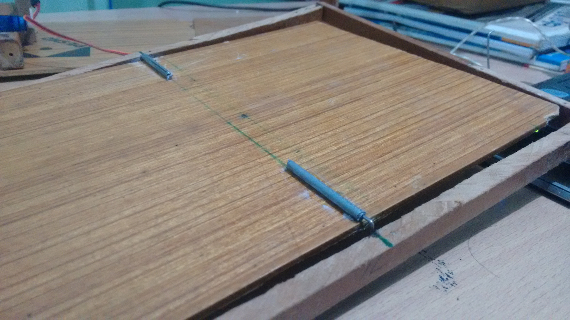
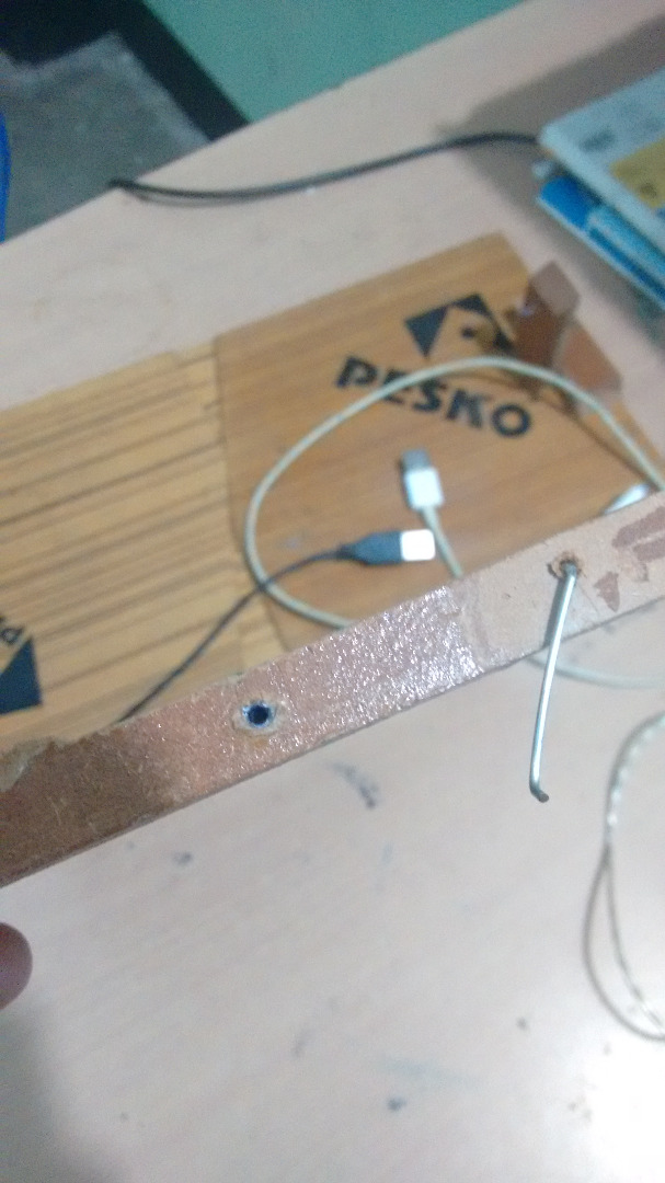
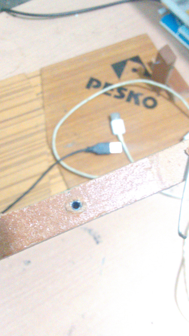
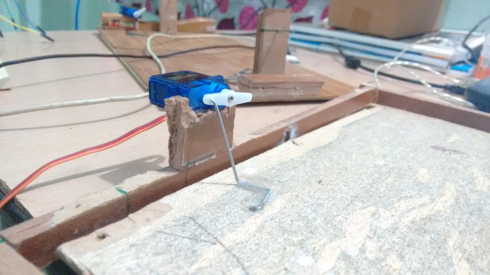
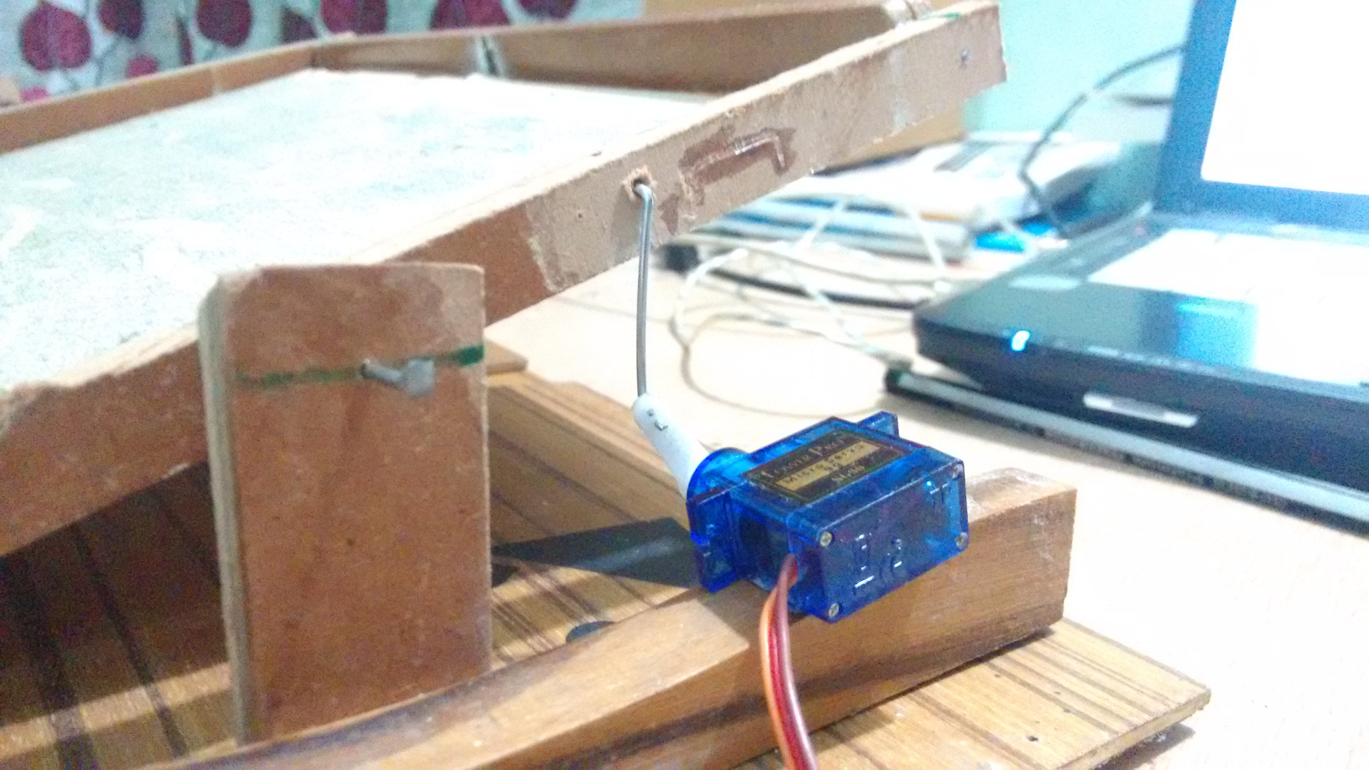
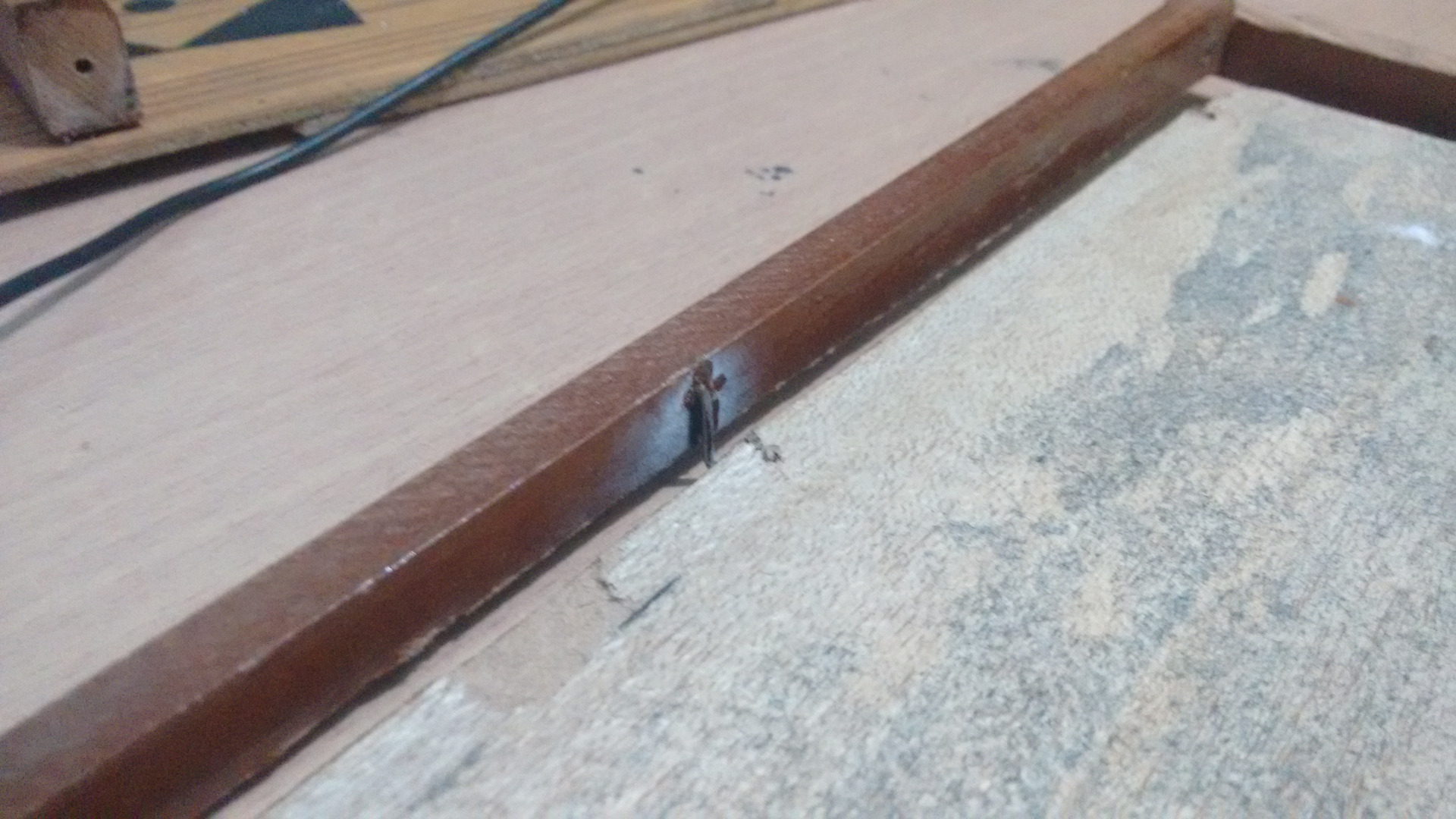
This the mechanical part of the project..
First for the base take long rectangle piece of wood plank or cardboard. it must be larger than the actual tilting board..
Cut two small equal size of cuboid wood ..
and add one nail to each ,in such a way that they are aline at the same height from the base . Also cut some extra piece of wood to add as a support to the pillars..
now for the top board ..
make a frame smaller than the base , this will be our x axis ,at the outside face of the smaller edges of the frame make small holes exactly at the centre of the edges. cut the rods into half and stick them to the large edges of the frame facing inwards. cut them into half before doing so.
this will hold the top board to the frame and will help in rotation.
now add the pillars to the outer holes to make the frame stand on the base.
stick the pillars to the base and also attach the supports to them.
now to add the the servo motors .
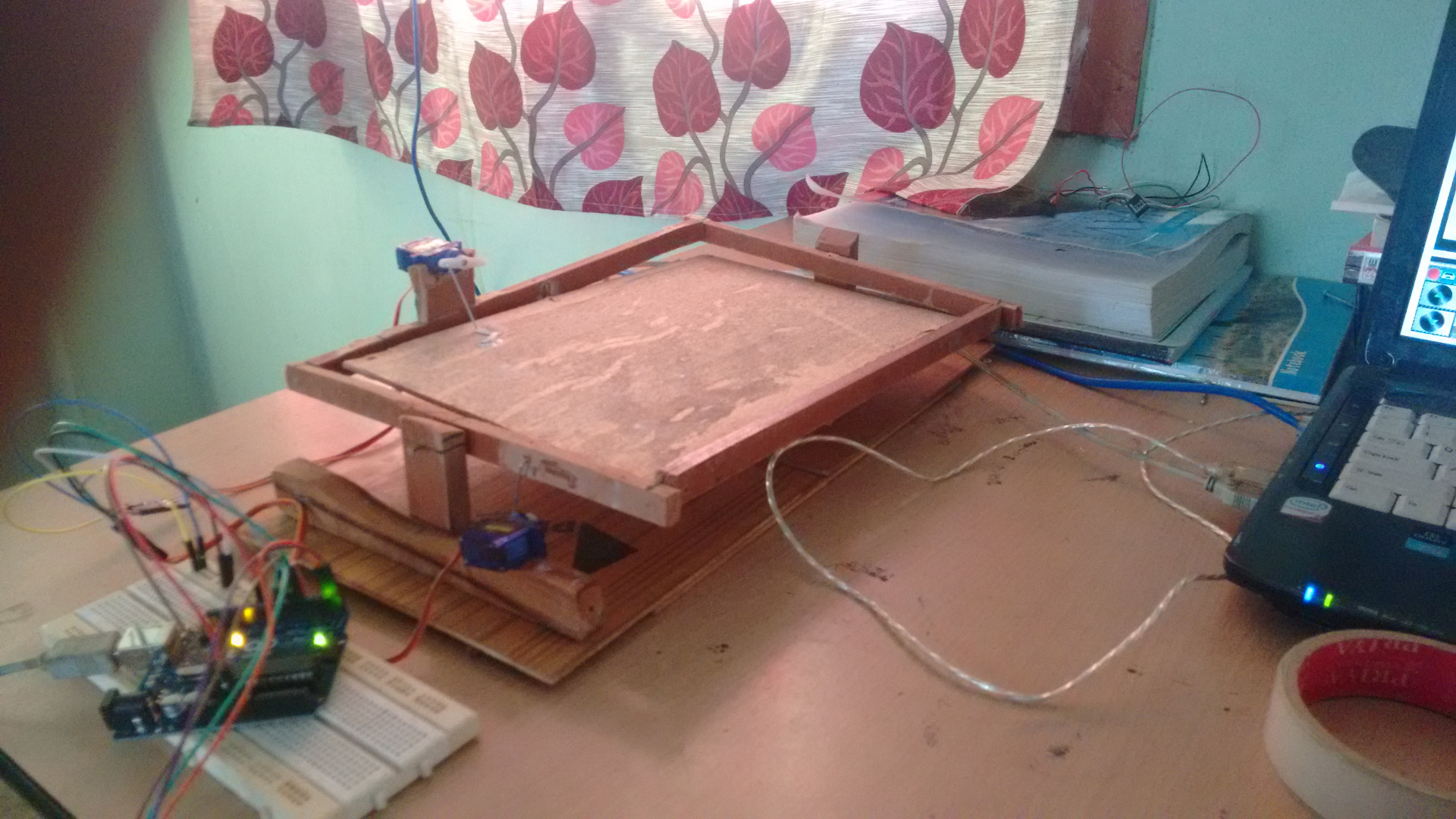
one will be attached to the base and will be attached to the frame using a small rod to rotate the frame
another will be attached to the frame and will be attached to the top Board using a small rod to rotate the top board.
the servos should be mounted perpendicular to each other as shown in the pics.
now the board is ready.
i made the maze using thermocol and a card board .
Setting Up the Circuit
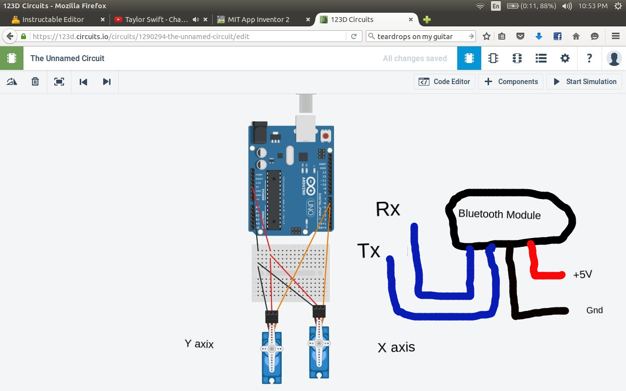
Set up the circuit as shown in the pic ...
Remember for servos i am using the red wire is positive, brown is negative and orange is signal.
Bluetooth module
Rx goes to pin 1
Tx goes to pin 0
Signal wire of base servo goes to pin 5
Signal wire of frame servo goes to pin 6
Remember to add additional power supply for the servo and bluetooth module.. other wise module wont get enough current and will keep on disconnecting , showing error 516. I had a lot of trouble troubleshooting it and at last figure out the problem and the solution.
Making the App
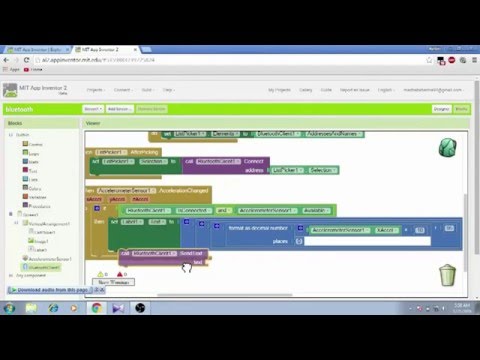
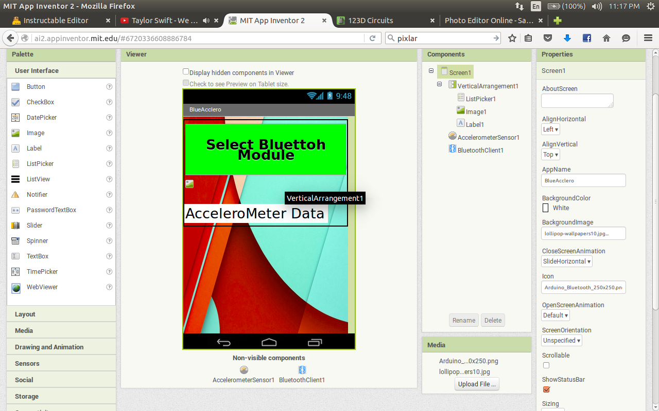
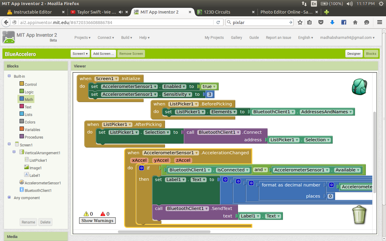
Okay first of all you need to login in mit app inventor for making any apps..
go to http://appinventor.mit.edu/explore/
and click on Create app! which in on the top right corner , sign up and you are ready to go....
Everything else i have shown in the video .. have a look.
here the basic :
when the screen is initialized in the app (Which in this case is Screen1),
-the accelerometerSensor Is enabled and the sensitivity is set to max i.e 3.
now when we press the list picker
-a list pops up, listing the paired devices.
(you will need to pair the module before opening the app, as normal the pair code is 1234)
Now before picking the list picker ,
-set the list with the paired devices and their addresses
After you select the device
-the bluetooth adapter will connect with the selected device
Now the module is connected
Now when the acclerometerSensor data is changed
-Add the data to the label text and send it with the bluetooth send.
Now the tricky part is sending the two data at a time
# acclerometer data ranges from 0 to 9.5 when tilted left and 0 to -9.5 when tilted to right,
same goes when the phone is tilted below and up wards..
so we have x and y axis tilting data that we need to send ...
let the data of x axis be X and y axis be Y
so what i did is this :
Text="( X*10(remove the decimal points after that)+95)*1000(multiply with 1000)+Y*10(remove the decimal points)+95"
so now the data ranges from 0 to 190 for each axis and is added to make 190180 where the first 3 digits are x axis and the last 3 are y axis coordinates ...
which will be send to the bluetooth module and will get broken down to the actual datas and map with the servo's rotation angles in arduino code...
Downloads
Writing the Arduino Code
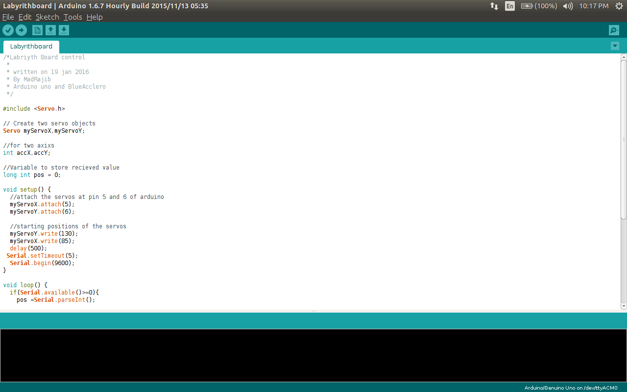
After the app is completed lets start withe code i have uploaded the code download it , compile and send it to the arduino but wait before you send the code detach the rx and tx pins of bluettoh module from the arduino board .. and send the code after this you can attach the pins back..
the code that is received from the bluetooth is a string which has our axis datas..
now Serial.parseInt(); is used to read the string and convert the string to int in a variable pos.
now pos has value = 190180 (say) our objective is now to decrypt the data i.e remove the x axis and y coordinates
for x axis . divide the value by 1000, this will give 190.i.e value/1000 = 190
and for y axis modular divide the value by 1000 , which will give us 180 i.e value%1000 = 180
now calculate the max and min position of the servos that you want for tilting the board ,... in my case its 180 and 75 and ....
now we got the x and y axis coordinated ,, now just we have to map the coordinates with the min and max rotational angles which we want for our servos ....
see the code for details .
And we are done ... upload the code , open the app connect and play....
Do you know google has one made for itself and is a very large labyrinth you have ever seen... which is also my motivation for building one for myself.
So till next time,have Fun..