Anay Shah - LED Chaser Game - Arduino & Microcontroller Tinkercad
by Anay Shah in Circuits > Arduino
1465 Views, 2 Favorites, 0 Comments
Anay Shah - LED Chaser Game - Arduino & Microcontroller Tinkercad
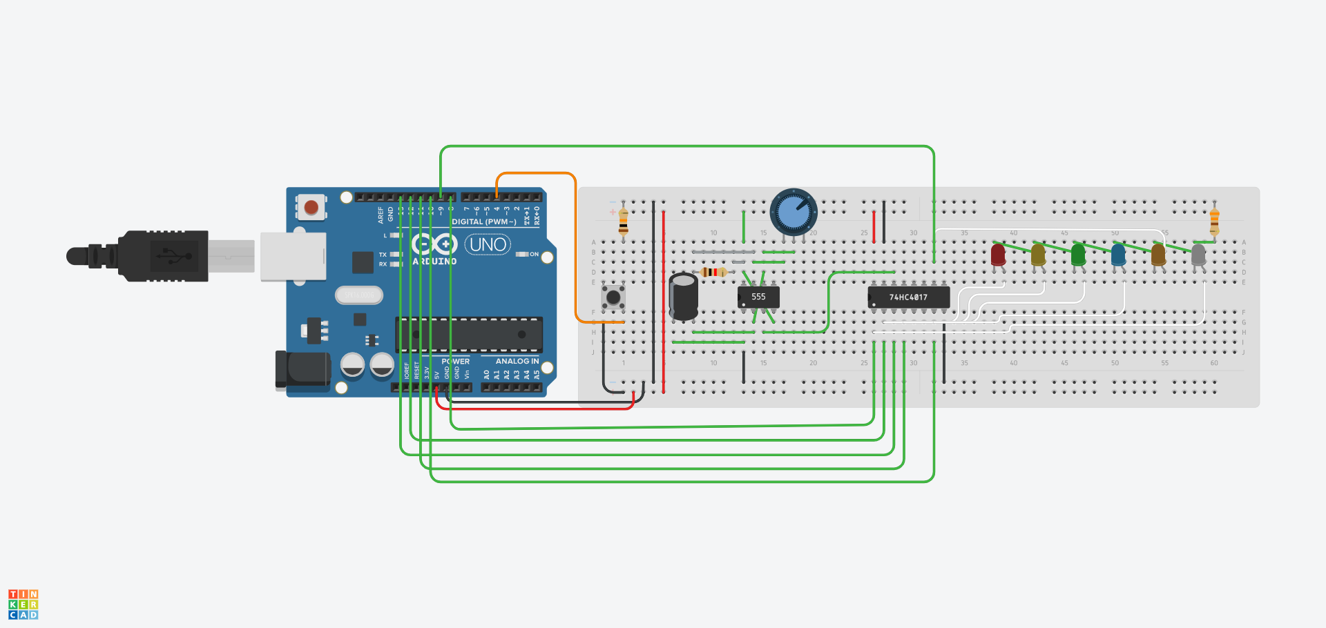
Welcome to the LED Chaser, a game that puts a person's reaction time and reflexes to the test. Using my acquired knowledge from our TEJ4M0 class (Computer Engineering), I am able to combine two units of the course: Arduino and Microcontrollers, to curate this game for you guys today. Hope you enjoy!!
Supplies
Setup
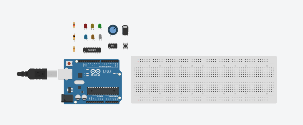
Begin by bringing in all of our LED Chaser components. This stage is really important since it makes the process and steps much easier to follow. This is also beneficial because everything is arranged, and you won't have to seek for parts after this stage is completed.
Creating the Base

Now it's time to get our hands full and put our components to work. Remember that we won't be getting any results right now because we won't be coding.
Shall we begin?
1) Wire in the 5V and GND pin from the Arduino into our breadboard just like the image.
Purpose: Allows for connectivity and enables the usage of the breadboard
2) Insert the 555 Timer as shown on the image. Make sure it is placed in the center of the breadboard so both north and south bridges of the breadboard have accessibility and connectivity.
Purpose: A timer that sends pulses to the LEDs and helps the Arduino communicate with the Push Button to help compare LED signals with the button signals.
3) Insert the Push Button.
Purpose: Basically the controller for your game. This component allows for you to gain points when clicked quickly and accurately to the LED color given to you when it appears.
4) Insert the Potentiometer
Purpose: The settings for your game. What this component does is gives you full control over how easy or difficult you would like to play this game. By rotating the potentiometer dial, this will change the speed at which the LEDs flash at.
5) Insert the Decade Counter as shown on the image. Make sure it is placed in the center of the breadboard so both north and south bridges of the breadboard have accessibility and connectivity.
Purpose: Since the 555 timer will be put in astable mode, it sends a pulse to the counter which then is acted as the power and functionality connector for all LEDs.
6) Lastly place all LEDs in sequence.
Purpose: As the main part of the game, the LEDs are used to visualize when each color is on/off to establish an appropriate time for the players to press their button to score points.
Wiring and Finalizing the Circuit
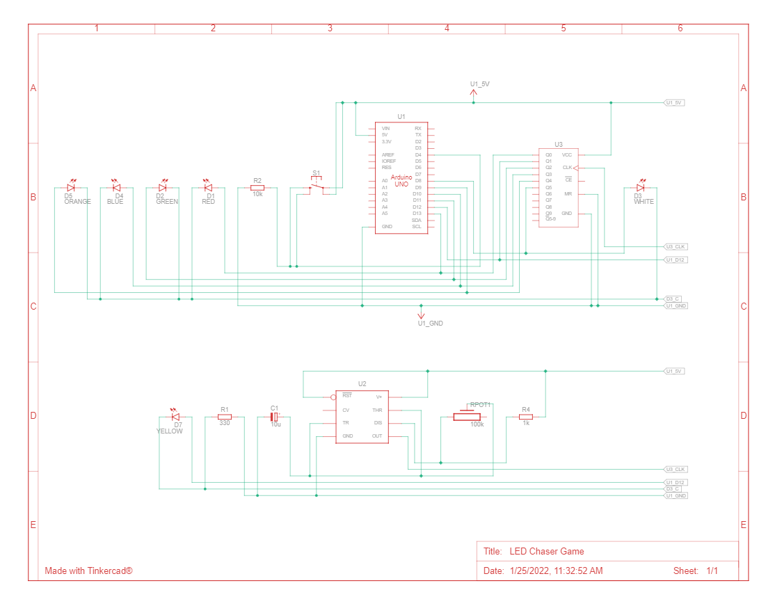
Now that we have completed Step 2 which helps create the foundation of the circuit, let's complete the circuit wiring. Our goal is for us to have flashing LEDs in sequence and the ability to change the speed of those LED flashes with the help of the Potentiometer.
Shall we begin?
1) Start by wiring the Push Button so that it has an input from the Arduino and PWR and GND from the breadboard with the help of wires and resistors. While we are it, you can also connect both ends of the circuit with PWR and GND so the entire breadboard has connectivity and functionality.
2) Moving on, let's connect our capacitor to our 555 timer. The negative pinout of the capacitor will be connected to our GND pinout (pin #1) and the positive pinout of the capacitor will be connected to our trigger pinout (pin#2). The trigger is an active low trigger, which means that the timer starts when voltage on pin 2 drops to below 1/3 of the supply voltage.
3) Now we can work on our 555 timer. As seen on the diagram this connection is a result of an "Astable" 555 timer configuration. Lets start by supplying PWR and GND to the 555 timer and then we can connect the trigger (pin#2) to the threshold (pin#6) and connect the reset (pin#4) to power (pin#8). In astable mode, the 555 timer acts as an oscillator that generates a square wave. The frequency of the wave can be adjusted by changing the values of two resistors and a capacitor connected to the chip.
4) Let's connect our Potentiometer next. Take the Wiper pinout from the Potentiometer and connect it to Threshold (pin#6) and take Terminal 1 pinout from the Potentiometer and connect it to Discharge (pin#7). This will allow for a change in speed for the LEDs, thus allowing for control over the difficulty settings for our game.
5) Progressing to our Decade Counter, let's start by connecting the PWR (pin#16) and Reset (pin#15) to PWR and GND of the breadboard. Now from the 555 timer "OUT" pin (pin#3), create a connection from that to the clock pin of the Decade Counter (pin#14). The clock pin is responsible for sequential output which will help our LEDs flash in sequence. Finally for the Decade Counter, take Arduino pins 13 to 8 and place in order into the output pins of the counter. This is a crucial step so the circuit knows which colours to prioritize as in our condition it will be from left to right.
6) Let's continue by wiring in our LEDs. From the counter "output" pins, connect to LED anodes in order. For example Output 1 from the counter will go into the Red LED as it is the first from the left. Continue this for all LEDs. Then we can use a shared 330 ohm resistor for all 6 LEDs. Make sure resistor is connected to GND and then proceed to create a connection to each LEDs cathode.
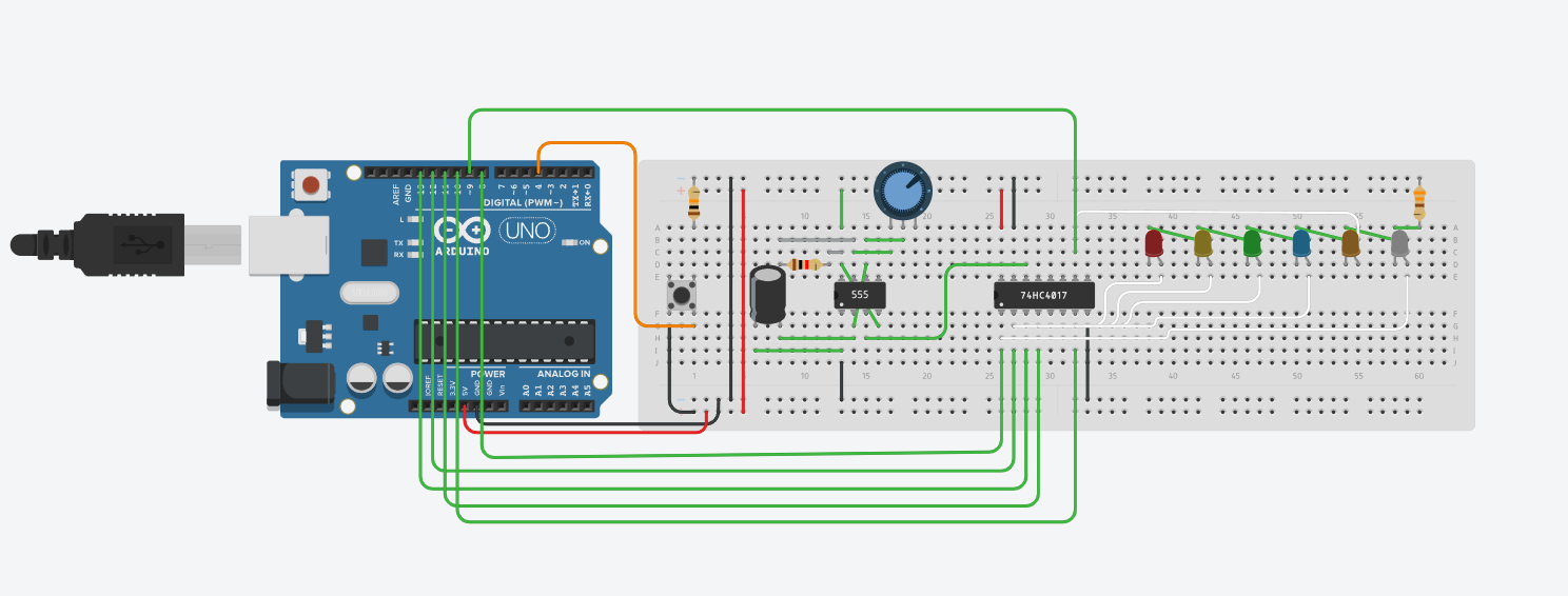
There you go, that is the wiring and complete circuit for you guys. Don't think we are done just yet, we still have to code!!
Final Circuit
Code
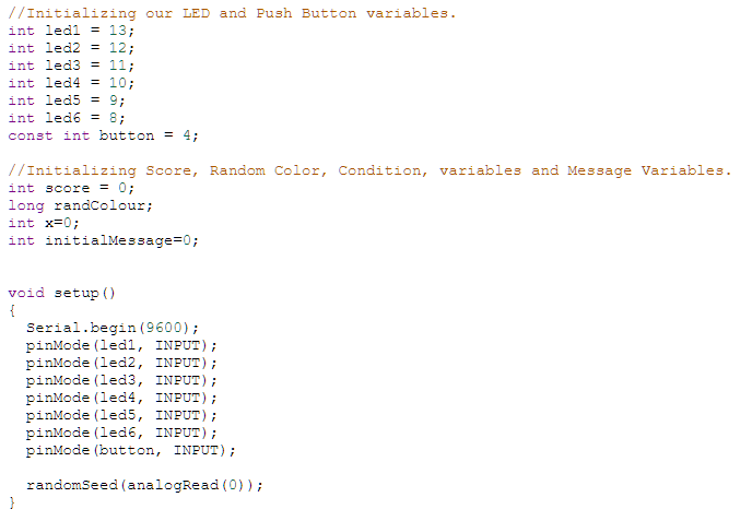
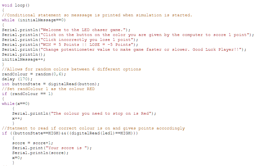
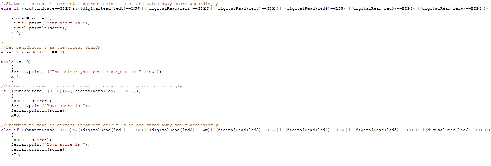


This is the TinkerCad code for the LED Chaser game. It simply checks for push button inputs to determine a winning or losing conditions. The code checks for the press of the button for the random colour given to us by the computer is turned on.
To start playing, make sure you start simulation --> open "Serial Monitor" --> check the colour given to you by the computer --> score as many points as you can!!
Throughout this code, there is a good amount of usage of the comments "//" as these are used to aid my thought process and justification for the code and why it was used.