An Adequate Thermometer

One fine night you realize that you are getting a fever. Questions like should I see a doctor at this time of night or should I wait till morning, Is my fever that bad or mild one? start bouncing in your head. You check your first aid kit for a thermometer, unfortunately you never bought one. This happened with me few days back. After getting back on feet, instead of purchasing a medical thermometer, I thought of making an adequate thermometer. You can make one for yourself using this guide, Let's get started.
(Note- Having a medical thermometer in your first aid kit is highly appreciated, but making one that is adequate enough is a joy in itself)
Things We Will Need (part 1)


Here is the list of electronics component and boards, we will need for this adequate thermometer.
- Arduino pro mini 3.3V ( This is to keep form factor small, 5V version will also do but schematic that I am attaching is for 3.3V board)
- FTDI FT232RL USB to TTL module. (For programming arduino pro mini)
- 128x64 graphic OLED display
- LM35 temperature sensor
- CR2032 button cell and holder (two in count , each)
- Jumper connector (It acts as switch, One in count)
In case of any doubt refer attached Images.
Things We Will Need (part 2)


Here is the list of prototyping material needed.
- Solder Iron and wire ( to put electrical components and board together)
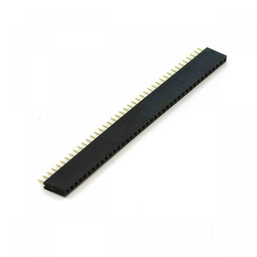
- Female berg strip (used while assembling)
- General purpose PCB (acts as host of our circuit)
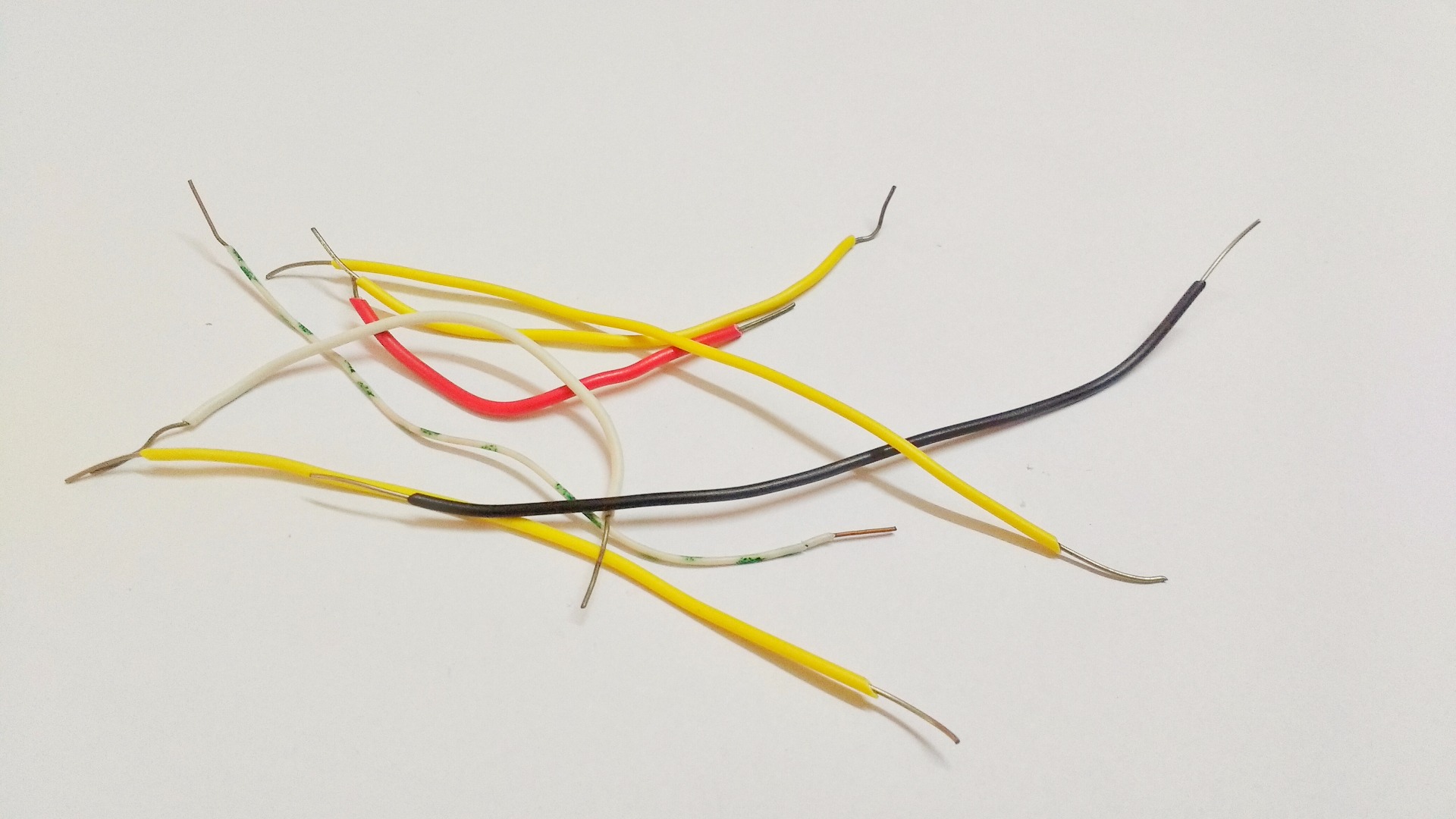
- small bunch of single core wires (to connect few things)
- heat shrink tubes (to insulate adjacent wire connections)
- Multi-meter (for debugging)
- Styrofoam (to insulate the bottom form place beneath)
- electrical tape
Preparing Sensor


Thermometer should have good accessibility, so we need to project our sensor, a bit outside our circuit board. For that we need to solder three, 3 cm wires to respective terminals of LM35 temperature sensor. In attached image
- RED wire is connected to Vcc pin of LM35.
- YELLOW wire is connected to Output pin of LM35.
- BLACK wire is connected to Ground pin of LM35.
After making these connections, use heat shrink as shown in attached image to isolate these connections form each other.
Now, We are ready with our sensor but before looking at our full circuit, let us first test our programming setup. As Arduino pro mini does not have onboard USB to TTL converter, we need to connect external USB to TTL converter such as FTDI FT232RL.
In case of any doubt refer attached video.
Programming Arduino Pro Mini (3.3V) Using FTDI FT232RL

I am attaching Schematic image for connection between Arduino pro mini and FTDI FT232RL. Make sure to change jumper to 3.3V location on FT232RL before making these connections. After that use suitable USB cable and try burning blink code.
Now, that we are done with programming setup let us look at complete circuit setup.
Schematic for Final Assembly


Here is the schematic for final assembly of the circuit on general purpose PCB using tools mentioned in step 2. Here are some details about the fritzing schematic and assembly.
- Two round objects in image are button cell with their holders.
- You can even insert a switch as shown in attached image.
- OLED connections are a bit messy, to get rid of confusion look at the note at right bottom of attached fritzing schematic.
- Use female berg strip, wires to create a compact assembly.
In case of any doubt leave a comment or refer the video at time location 4m47sec.
In next step we will look at the arduino code needed for this device.
Code

I have attached code for this thermometer, it is quite simple. Before you try to compile it you need to perform following functions.
- Install u8glib library ( https://github.com/olikraus/u8glib), for using OLED on arduino.
- Attached code displays symbol of thermometer on right side of OLED. In case you want to display any other symbol you can do it using 'LCD assistant' software, here is the link to download the same- http://en.radzio.dxp.pl/bitmap_converter/
- After generating necessary data for displaying your symbol, replace 'therm_bitmap' variable data with your data.
- Make sure that while uploading code, connection from button cell is open.
- Finally compile and upload.
In case of any doubt in code, refer to attached video at 6m 59sec.
Downloads
Finish


After uploading code on assembled circuit, it should look something like attached image. In case of any emergency concerning temperature, this tool will come handy. Beside, while making this you get to learn a lot. Finally seeing your keens using your device is a thing of ultimate joy.
Thanks for your time.