Ambigram Name Spinner - the Art of Taking Turns
by Xorus in Workshop > 3D Printing
1131 Views, 4 Favorites, 0 Comments
Ambigram Name Spinner - the Art of Taking Turns
You took out the trash last time, so now it's your partner's turn. Probably.
The bigger question is: Whose turn is it to do that sink full of dirty dishes?
With this ambigram spinner, you can determine whose turn it is to do any job, big or small, in just seconds. Just give it a spin, and it will tell you with complete certainty whose "turn" it is to do anything!
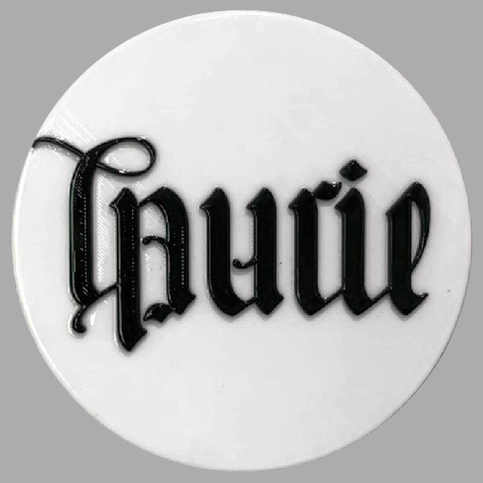
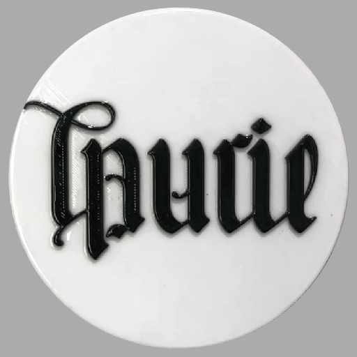
In case you didn't know, an ambigram uses clever typography so the text can be read as one name when viewed upright, and can be read as another name upside-down. This example says "Laurie" upright, and "Mark" upside-down.
If you prefer not to use the ambigram name spinner to assign chores, you can instead use it for more positive uses, like determining who gets the bigger piece of cake, who gets to receive a shoulder massage, or who gets to pick the next movie to watch.
How you use it is up to you! I'm just here to help you build it.
Supplies

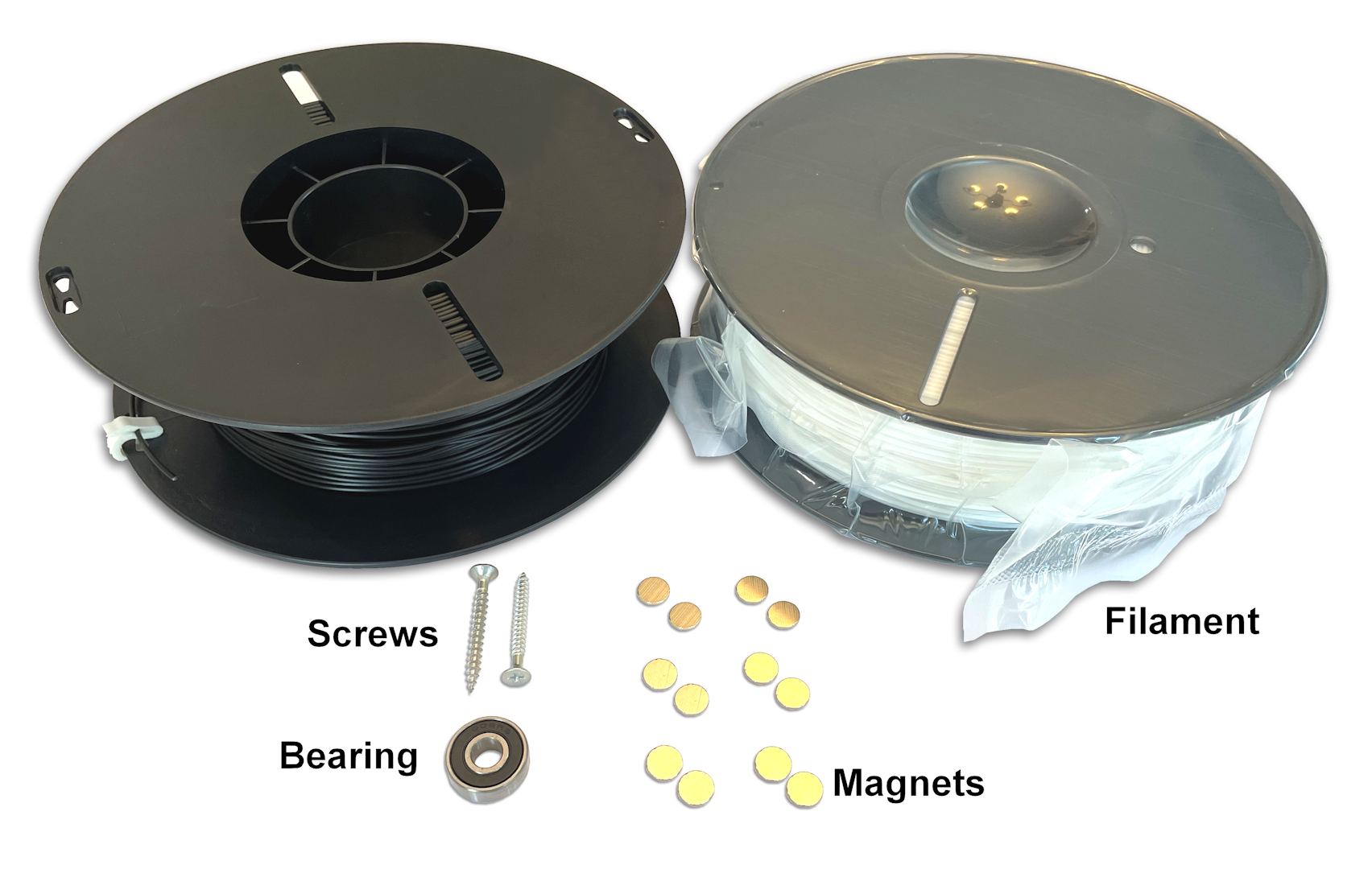
You will need the following things to complete this Instructable:
- One (1) rotational ambigram where the text says one name when read upright, and another name when read upside-down
- One (1) common 608 "skateboard" ball bearing with dimensions 8mm x 22mm x 7mm (Amazon)
- Access to a 3D Printer and some black and white filament (Amazon)
- [Optional, but recommended] Two (2) screws suitable for wall mounting
- [Optional, but recommended] Twelve (12) thin Neodymium magnets with dimensions 10mm x 1mm (Amazon)
Import the Ambigram Text

First, we will need to create and import the ambigram text for the spinner. An ambigram is a text design that can be read right-side-up or upside-down. Getting the text on the top of the spinner to be as legible as possible in both orientations is arguably the most important step in this Instructable.
You can create your own ambigram, hire a professional, or use the ambigram generator at FlipScript.com to create a high quality ambigram design for you. For this example, I am using an ambigram from FlipScript that says "Laurie" when it is read upright and "Mark" when it is read upside-down. I am including it here for completeness.
I am also including the final .stl file here if you would like to see how the completed model comes out.
Once you get your ambigram file, you will need to import it into your workspace. In Fusion 360, click the Insert menu and select Insert SVG. In Tinkercad, click the Import button. Either way, navigate to where your ambigram SVG file is saved and import it.
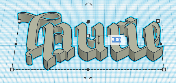
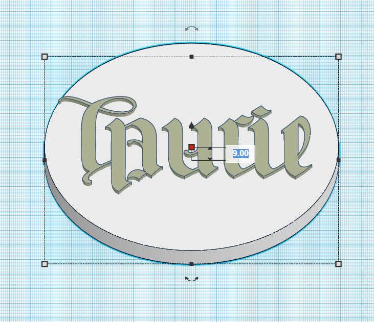
After importing, increase the height of the ambigram text to 9mm.
Create the Spinner Disks
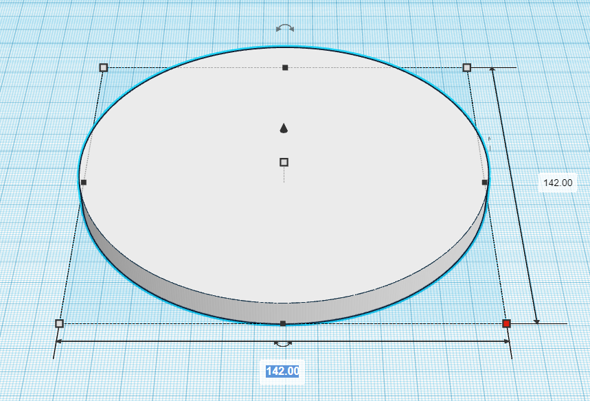
Now, create a circular disk that will become a base for the ambigram to sit on. I measured a few objects of about the same diameter that I wanted the disk to be, and found that 142mm was about the size that I wanted. It does seem about right. So, create a cylinder that is 142mm in both the x and y dimensions, and 7mm tall.
Resize the ambigram that you imported earlier to fit on the top of the disk. Either use alignment tools to center the ambigram on the disk in the x and y axis, or eyeball it. I decided to use the good ol' eyeball method to make it appear centered, even though it technically isn't, since the long tail of the "L" was messing with the computed alignment. Note: If you scaled all 3 dimensions of the ambigram while resizing, make sure to set the height back to 9mm so the ambigram just slightly clears the top of the disk.
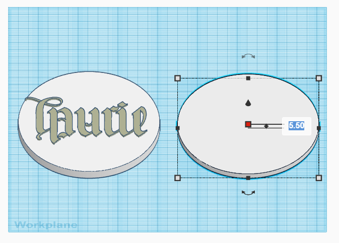
Copy and paste a duplicate disk next to the original disk (CTRL-C, then CTRL-V), and change its height to 5.5mm. This second disk will be the stationary bottom part, allowing the top disk to rotate.
Give It Some Spin
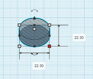
Next, we will allow the top disk to smoothly spin by incorporating a 608 "skateboard" ball bearing into the bottom. Create a cylinder hole that is 7mm tall with a diameter that is slightly larger than the bearing's outer diameter of 22mm. This may vary slightly depending on your 3D printer, but I found that a 22.3mm diameter worked well.
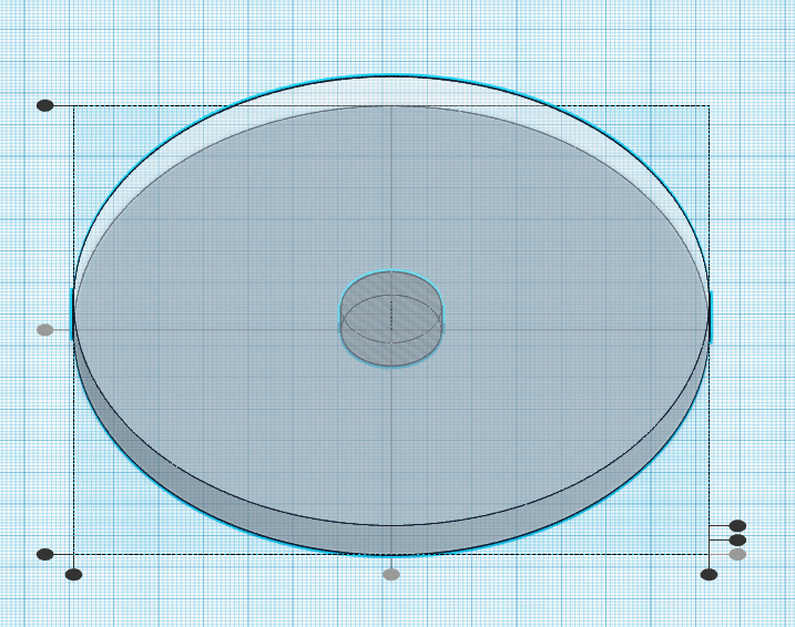
Position the bearing cylinder hole in the exact x and y axis center of the top disk. You can do this in Fusion 360 by selecting Modify, Align or in Tinkercad by clicking the Align button. Once the bearing hole is centered under the top disk, combine the shapes, which will subtract the hole from the disk. Make sure to combine the ambigram with the disk first if the hole looks like it is going to touch the ambigram design.
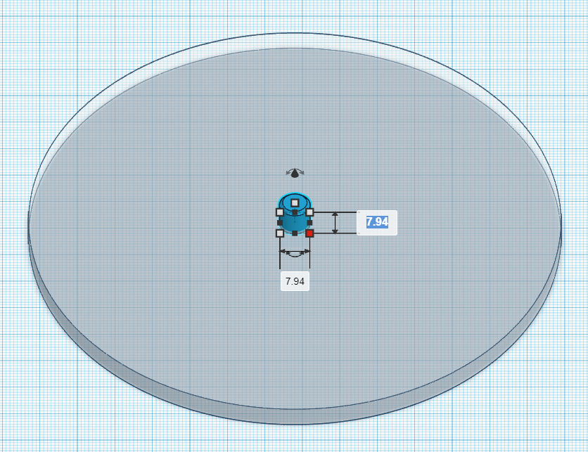
To finish the bearing connection, create a pin on the bottom disk that will go into the center of the bearing. To do this, create a solid cylinder that extends 7.2mm from the top of the disk. Being a tiny bit taller than the bearing will create a small air gap between the disks, and allow them to spin with little friction. The pin should also be slightly smaller than the bearing's 8mm inner diameter. I used 7.94mm, which was a nice snug fit, without being too snug. A slight chamfer on the top edge might make it easier to push the pin into the bearing, although I've been known to use sandpaper when necessary.
For a basic spinner, that's really all you need! You could print the model as it is, put some rubber feet on the bottom, and use it as a free-wheeling table-top spinner!
However, there are some extra steps you could do to make it even cooler.
Hang It Up
Unless you have some kind of external pointer (or create one as part of the bottom disk), there isn't a way to know which name is being "selected" at this stage. An intuitive way of showing the name being selected would simply be to display it upright, so the names are in a normal, readable orientation. To do that, we will need to wall mount the spinner vertically.
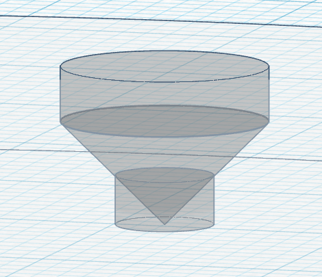
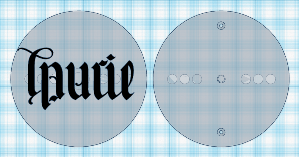
Find some screws lying around, make a few measurements, and create a couple of suitable screw holes for the bottom disk. Make sure to recess the screw heads, so they don't interfere with the spinning mechanism! I stacked a cylinder, a cone and another cylinder to create a rough approximation of the screws that I found.
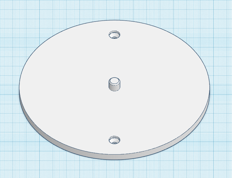
Turn the screw shapes into holes and subtract them from the bottom disk. The mountable bottom disk should look like the second picture.
Again, the project could be considered complete at this point. However, the free motion of the spinner may not clearly indicate one of the two names. Have you ever played "spin the bottle", and had the bottle end up pointing directly between two people? Awkward!
Snapping Into Position
We can encourage the spinner to stop at one of our two desired orientations using embedded magnets. This gets a little tricky, though, because we want the magnetic field to be powerful enough to snap the spinner into one of two possible orientations, but not so powerful that it would prevent the spinner from rotating relatively freely. It would be nice to complete a bunch of full revolutions before the spinner snaps into position, so we know for certain that the name selection was random, and not due to someone's incredible spinning talent. So, it's a bit of a balancing act.
I found that one of the best ways to handle this was to make sure that the magnets never make direct contact. Once they touch, they snap together and all movement instantly stops. So, I wanted to embed the magnets directly into the 3D print and keep them far enough apart so that they can pass by each other freely, while still feeling the effects of the magnetic field, especially at slower speeds. Embedding the magnets directly into the 3D print also protects the magnets from moisture, wear and rust.
The magnets I used are 10mm x 1mm thin Neodymium magnets. Since the tolerances of the embedded magnet holes aren't as tight as the tolerances for the bearing, and since there is no easy way to sand their little magnet pockets while the model is being 3D printed if the fit is too tight, I gave them a little more room to slide in easily.
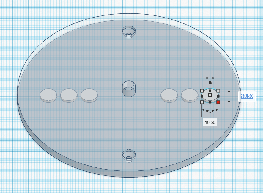
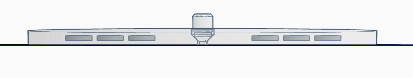
Create a cylindrical hole that is 10.5mm in diameter and 1.5mm tall and position it 2mm up on the z-axis. Duplicate this hole 5 more times (6 total) and position the holes in a line across the center of the disk. Exact spacing does not matter, as long as the spacing matches on both disks, but you will want to give them a little space to breathe since they will want to snap together if you place them too close.
The side view of the bottom disk with the embedded magnets should look something like the second picture.
Finally, duplicate the entire row of holes, and place them into the top disk. They should remain at the same height on the z-axis in order to make the 3D printing process easier.
Creating the 3D Print
For contrast, I decided to print the text in black, so I changed the color to black in the rendering as well. Your final design before saving and slicing should look something like this first picture (but with your own ambigram text, of course). I made the rendering transparent to be able to see into the middle, since there would be no other way to know that those magnet holes were in there.
I printed with White PLA for the disks and Black PLA for the text, using a layer height of 0.2mm and 15% infill. Be a bit generous with the number of outer walls, since that extra weight on the outer edge of the top disk will help with the spinning action. I used 6 outer walls, and I get quite a long spin before the magnetic field and a small amount of friction slows the rotation down (see video above).
Only the bearing hole on the bottom side of the top disk has any overhangs, so if your printer is well calibrated, you should not need supports. If you do decide to use supports, make sure to optimize for easy break away over strength.
However, you will need to add in some layer pauses (this can be done with gcode command M600). Depending on what slicer you use, there may be a way to do this directly in your slicer. If there isn't, you will need to manually add it to the gcode yourself. If you need help with this part, there are lots of video tutorials on how to use the M600 command during 3D printing.
There are two (2) very important pauses that you will need to add to the 3D Print gcode:
- Pause for the placement of the six embedded magnets into their pockets on the top and bottom disk
- Pause for the filament change to the color of the text
To find out where to place the pauses, use your slicer to step through the layers one-by-one, looking for the layer that covers the top of the magnet holes. Once you find that layer, insert gcode command M600 just *before* that layer begins, which will stop the print and allow you to do what you need to do. At that point, you will want to drop a magnet into each of the magnet holes, being careful to make sure the magnet orientations are all facing the same direction. Then, let the print continue, which will cover the magnets in filament.
Similarly, look for the layer when the ambigram text on top just starts to print, and insert an M600 pause just before that text layer begins so you can change the filament color to the one you want on the top of your spinner.
Assembly
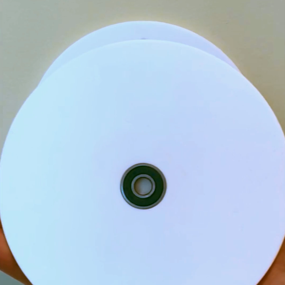
Assembly is fairly simple. Just insert the screws into the screw holes, make sure the holes are vertically aligned, and screw the bottom disk to the wall. Screw into a stud, or use wall anchors if desired. Then push your 608 bearing into the top disk, and slide the whole top disk plus bearing piece onto the pin of the bottom disk.
Then, spin away and cross your fingers that it won't be your turn to do those dishes!