Alibre Starter for People Like Me!
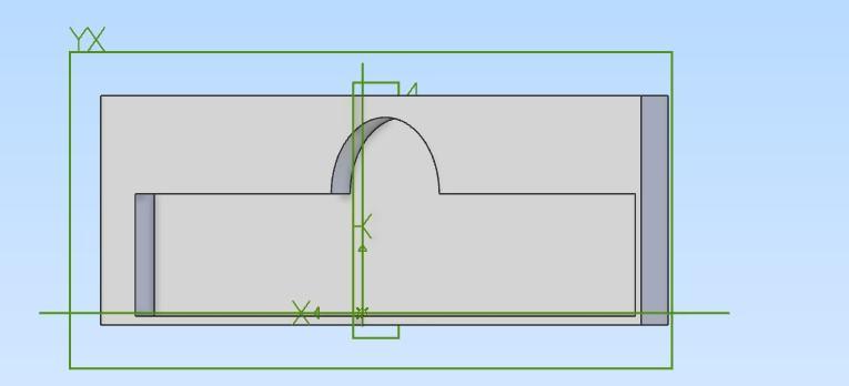
I am new and a definite novice in the field of CAD, CAM, and building parts but...
I found a neat piece of software from Alibre. It is called Atom3D. Affordable. Yes. Learning Curve. Maybe. Easy on the eyes...definitely.
I have been testing the patience of the Alibre people and their users for weeks and months trying to figure out how McMaster-Carr builds their .step files into glorious bolts, hex head screws, and other parts that are a necessity for anyone who uses mechanical fasteners and other OEM and non-OEM parts to construct.
I have failed so far but...
- I have gotten close at times without fully engulfing my endeavor into the craft of CAD infrastructure.
- I tinker at times but can be serious.
- The Alibre suit of tools allows for manipulating and advancing construction of so-said parts and fasteners.
There is actually a reasonably priced Alibre design source called Atom3D. This is all I can afford for me and my uses. So, I picked it up and started to build.
I will show off parts later. For now, I am learning about the vast array of use cases for CAD (of course) and building when using the export tool within this CAD source to make use of a 3D Printer.
Seth
Supplies
3D Printer
Development Desktop
Files or the ability to build your own Files virtually on the Dev. Desktop
Altering files is a first choice! This way, one can learn while altering other peoples' works.
Show Off!
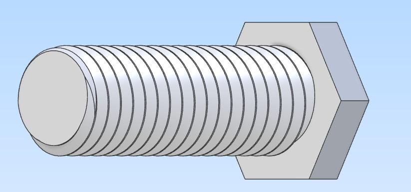
I built this in time. It only took me, with a lack of education in CAD programming and utilization, three months to be able to alter it to suit my needs no matter what!
So, without further ado, here we go...
Ideas
- First and foremost, get your CAD program ready and set it to mm.
- Next, make a circle and Boss Extrude it.
- One can make this extrusion of the circle 25mm say...
- Oh and if you want, make the circle of any diameter, i.e. say 10mm?
- Now...
Other Notions
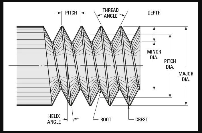
After reviewing the screw-thread-terminology post and photo, one can make some educated assumptions that may or may not work out. For once in time, I thought I could just post an extruded circle and then build upon it but how?
I did not know. I read articles and watched videos. I should have gotten a step guide of a book to walk me through CAD programming and building in CAD sources.
Actually, some of the articles were useful and got me far. I got to make threads on the Boss Extruded circle by means of a core set of principles.
- Threads and the inner working of fasteners are far more complicated that I can admit to currently.
- For one, shear strength and tensile strength play a major role in what type of material a bolt, so to say, would need to be made for a use case.
- Speaking of major...
- There is a minor and major diameter in specified bolts at different locations throughout specific fasteners.
- Interesting or complicated? Either way, the minor diameter is closest to the inner helix measured angle nearest to the centroid of the circle before it gets extruded by the Boss Extrusion tool within Alibre (from what I find).
- The major diameter is the furthest extent of the threaded area of the bolt, screw, and so on or crest to crest at 180 degrees.
Anyway, here is a photo instead of my jargon.
Ideas and Notions
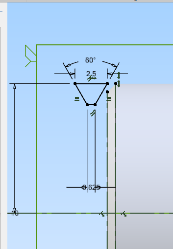
As we look over the bolt in question with all the facets, let us take a deep breathe...
So, something like the Sketching tool would be used to handle the equal constraints of 60 degrees on the left and right side of our trapezoid (USA). So, if you have an eight mm bolt in diameter and want to have a correct thread pitch, and again beginner stuff for me while being a novice, on the lower extent of the trapezoid, type your pitch and divide by four.
Example:
Pitch = 1.25
Bolt Diameter = 8mm
For minor diameter of the thread, we use a simple formula: (Pitch / 4) = 0.3125mm
We can enter in the sketching tool once we boss extrude the circle on any plane fathomable. Oh! Use the chamfer tool to make a small chamfer on the end of the boss extruded circle that is now a cylinder.
This will make it easy to create a similar trapezoid/quadrilateral with specified parts by way of the line tool when building it.
So far, we should have a built Alibre file of sorts that we can now exit out of the Sketching tool view and back into the "building" views tool(s).
Then, we would want to make a helical cut into the surface of the cylinder that can be tedious to figure out if you are new in the realm of Alibre or CAD in general.
All fun aside, those people at Alibre have a pretty nifty view on CAD and interfacing CAM products with their use cases. And few to that, I have enjoyed running my computer constantly figuring out what I can build next.
Anyway, back to business.
So, did it work? Are you lost? Should I have used more videos and photos?
Godspeed! CAD is ever evolving but which one of the types of programs should you pick? No clue. Personal preference really...
One thing I do know, is I am building fasteners and making HHS (Hex Head Screws) from my own builds. Now, are they perfect yet? No. By far, they need work. My issue!
Seth
Summarization
I think sometimes in life, people need to fill their time doing something productive. CAD entails productivity.
I mean what? You can use a file, save it, import another file to change up, and/or build a file in your CAD program, then export that completed set (the FILE) as a useful formatted file, and then finally build it in real time with inexpensive machines or with real, fine detailed machines that will make you quiver.
But be careful with CAD/CAM products! They are resource hungry. Strong development desktops are needed with good graphics, i.e. especially the graphics part if you want to build specific, combined logic type CAD assemblies.
Seth