Alarmostat
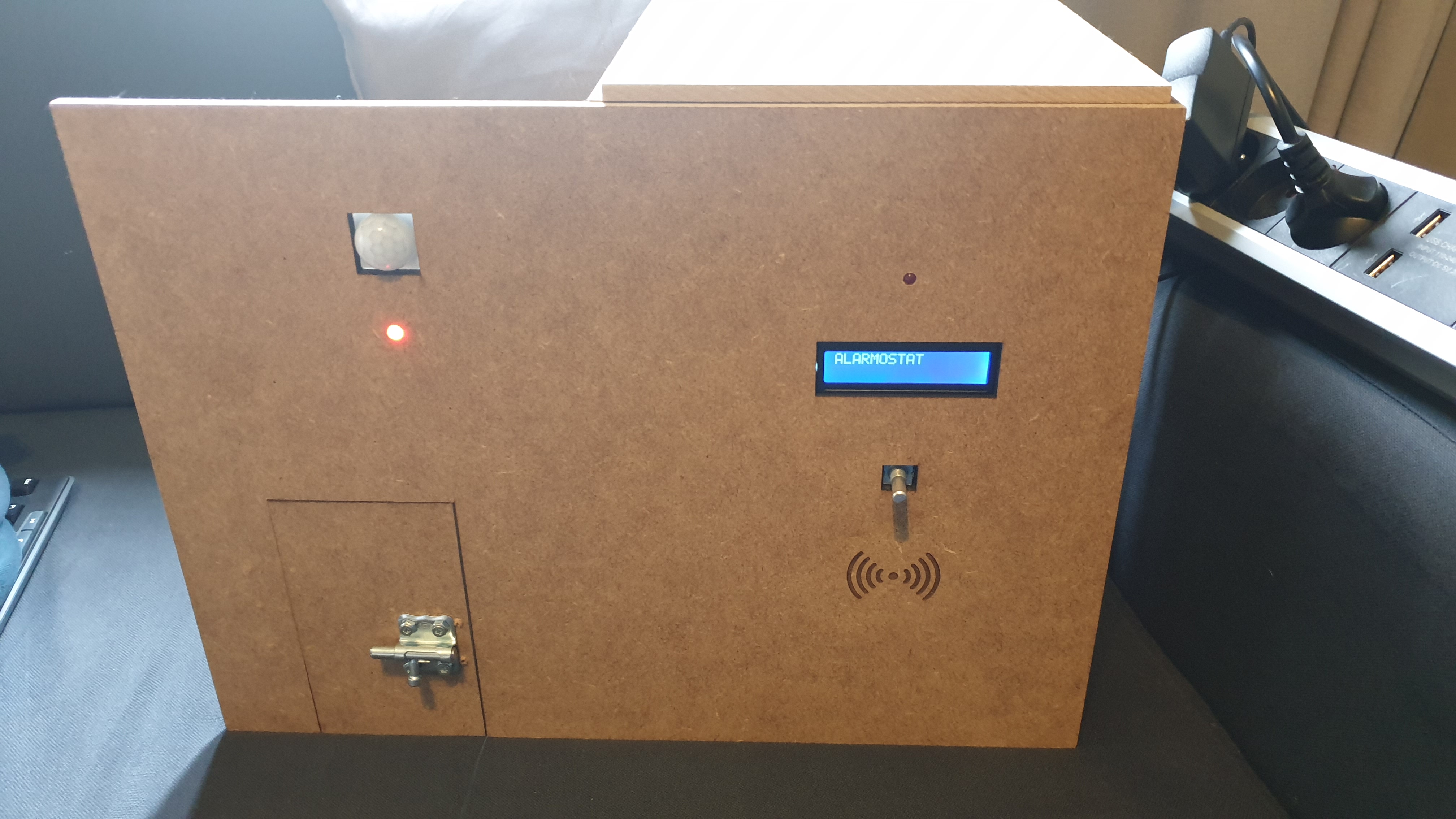
In this guide I'll be telling you how to build Alarmostat, my school project for 1MCT at Howest. The concept is making a device that incorporates both a burglar alarm and a thermostat in one. My design can definitely be improved though, so it's not needed to follow the instructions super precisely. Be creative!
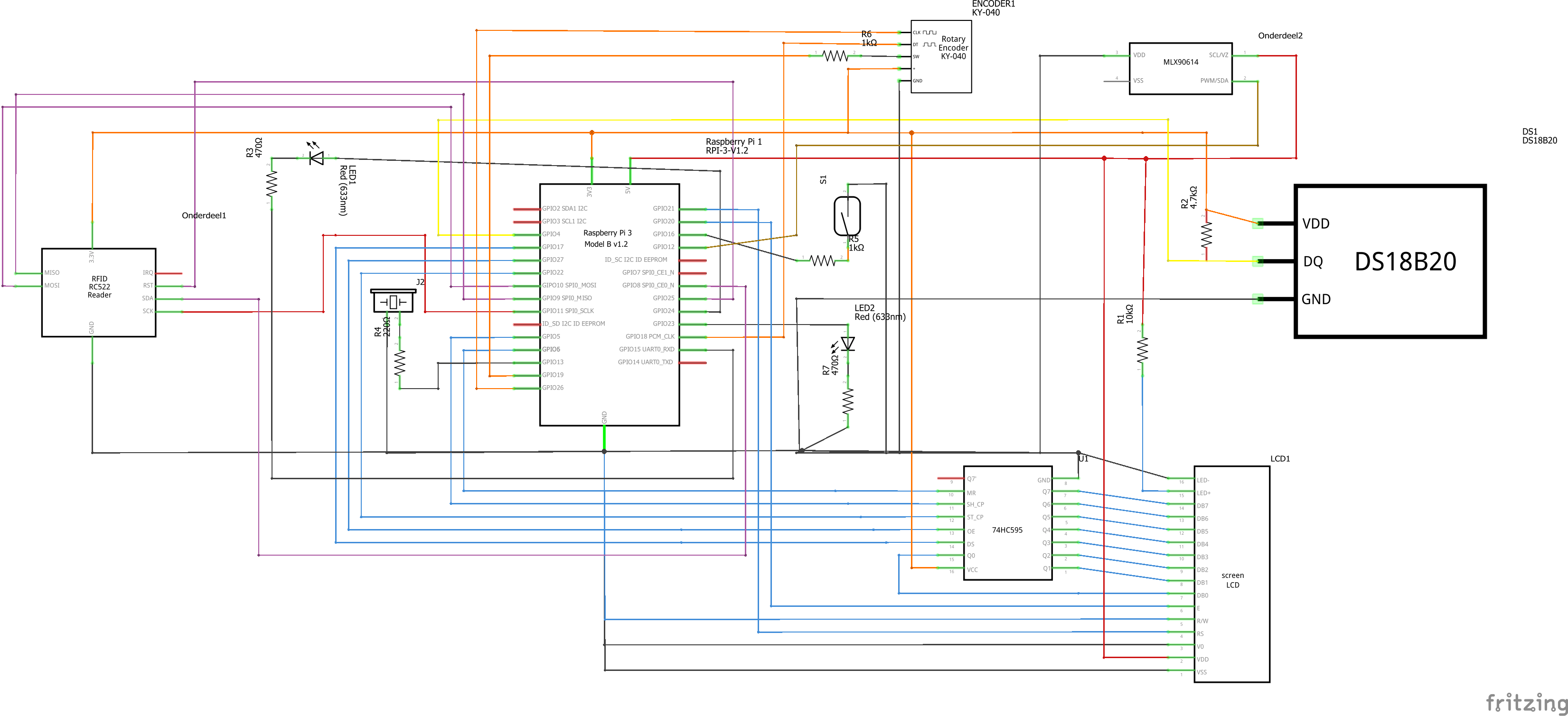
The components needed are listed below, and the exact electrical circuit can be found in the photo (I'm not responsible for any damage to your equipment though :) )
Supplies
-Raspberry Pi (I used a 3B+) with adapter and sd card
-Breadboard
-GPIO breakout board can be handy
-Motion sensor (HCRS501)
-Door magnet switch (ada375)
-a few leds and resistors
-an active buzzer
-rotary encoder (keyes-0.40)
-2x16 lcd display
-74hc595 shiftregister to drive the lcd
-MFRC522 rfid reader
-a lot of wires
-materials to make a case and tools to put it together
(extra breadboard power supply)
Getting the Files
The files for this project can be found in these repositories:
https://github.com/thomasdebiehw/project-backend
https://github.com/thomasdebiehw/project-frontend
The backend is a Python / Flask program that communicates with our hardware and serves the information from it to the frontend, which is a webinterface.
Don't hate on the code, I am aware that some of it is written poorly and unclear, but hey, it works :)
You might have to change some things around for it to properly work, like the mysql user or ip-adresses the programs run on.
Read the readme of the frontend to know where to put these files
Get the files on your Pi (or make awesome changes to them), and get ready to connect everything to the Pi.
Connecting

Power off your Pi before connecting the components. The electrical circuit should be pretty self explanatory, but one part to watch out for is the motion sensor. For some reason its layout is different on the electrical circuit. I added some annotations to the image to explain the function of the components.
One thing you might want to do, should you run into issues, is use an external breadboard power supply. I had some problems with the rfid reader not working. Although I am not entirely sure power was the issue, I didn't experience it after using an external source and it doesn't hurt either.
If you want to do this, connect the GND pins from the Pi and the power supply together. Plug everything +3.3v or +5v from the components into the according output of the external supply, and you should be good.
DON'T connect the Pi's 3.3 or 5v to the power supply. If you're using one its best to leave these completely disconnected to avoid making mistakes.
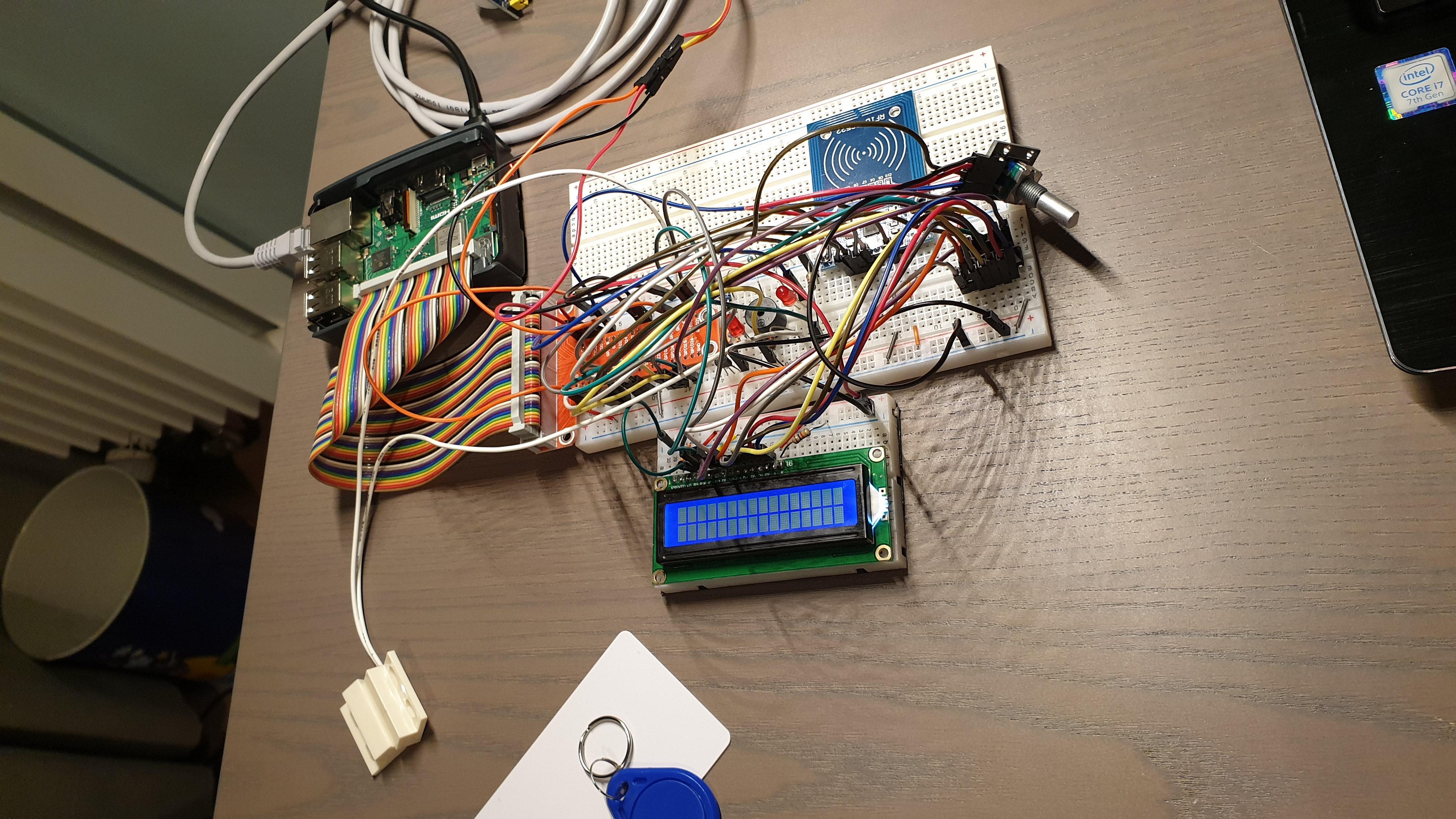
You can see my testing setup in the second picture
Testing
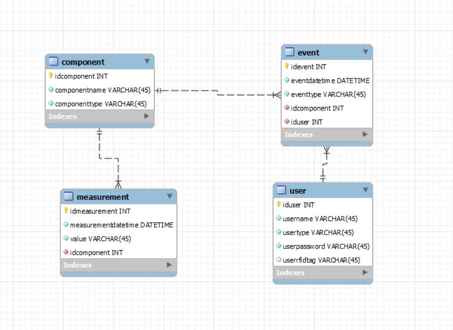
You should put the database on the Pi via MySQL Workbench by doing a data import. The file in the repository is a dump of the database. Otherwise you might run into some problems because the Pi uses MariaDB instead of MySQL. You may also have to create a new user or change these credentials in the code. You can see the ERD in the attached picture
You can try to run the Alarmostat program immediately, but I recommend testing the components seperately first. You could use the classes included in the github repo, and make a little program to test all your components. That'll make troubleshooting a whole lot easier.
Once you know your components work, we can start building a case.
Case

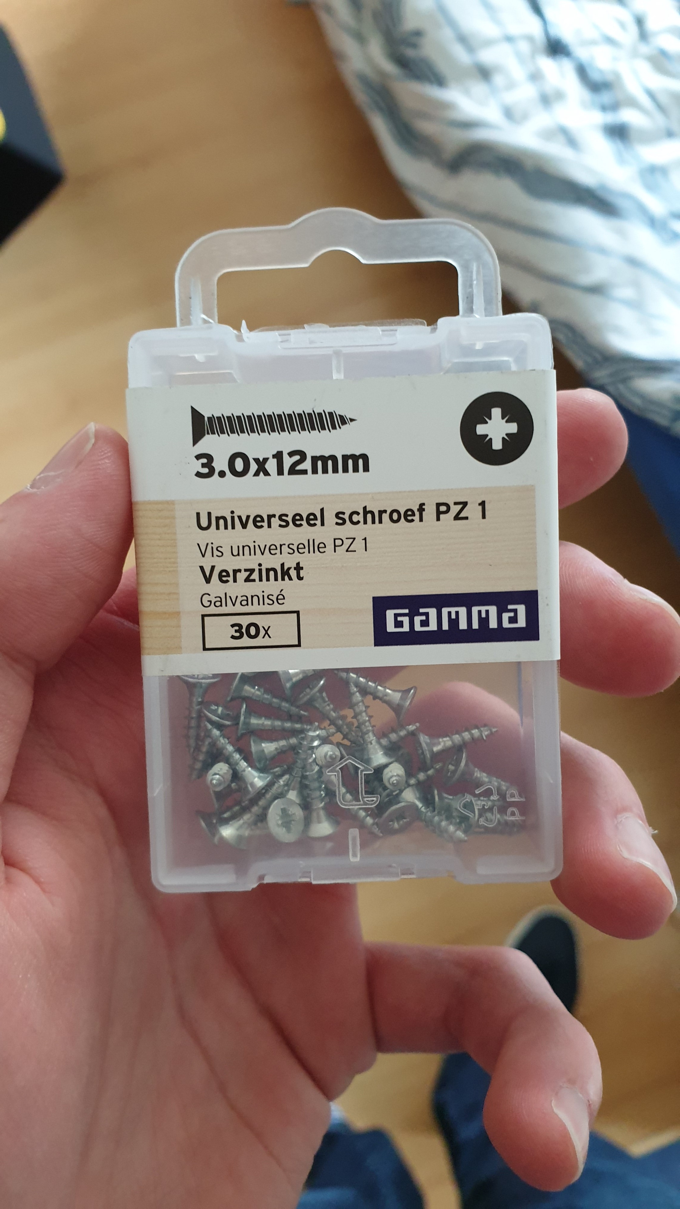
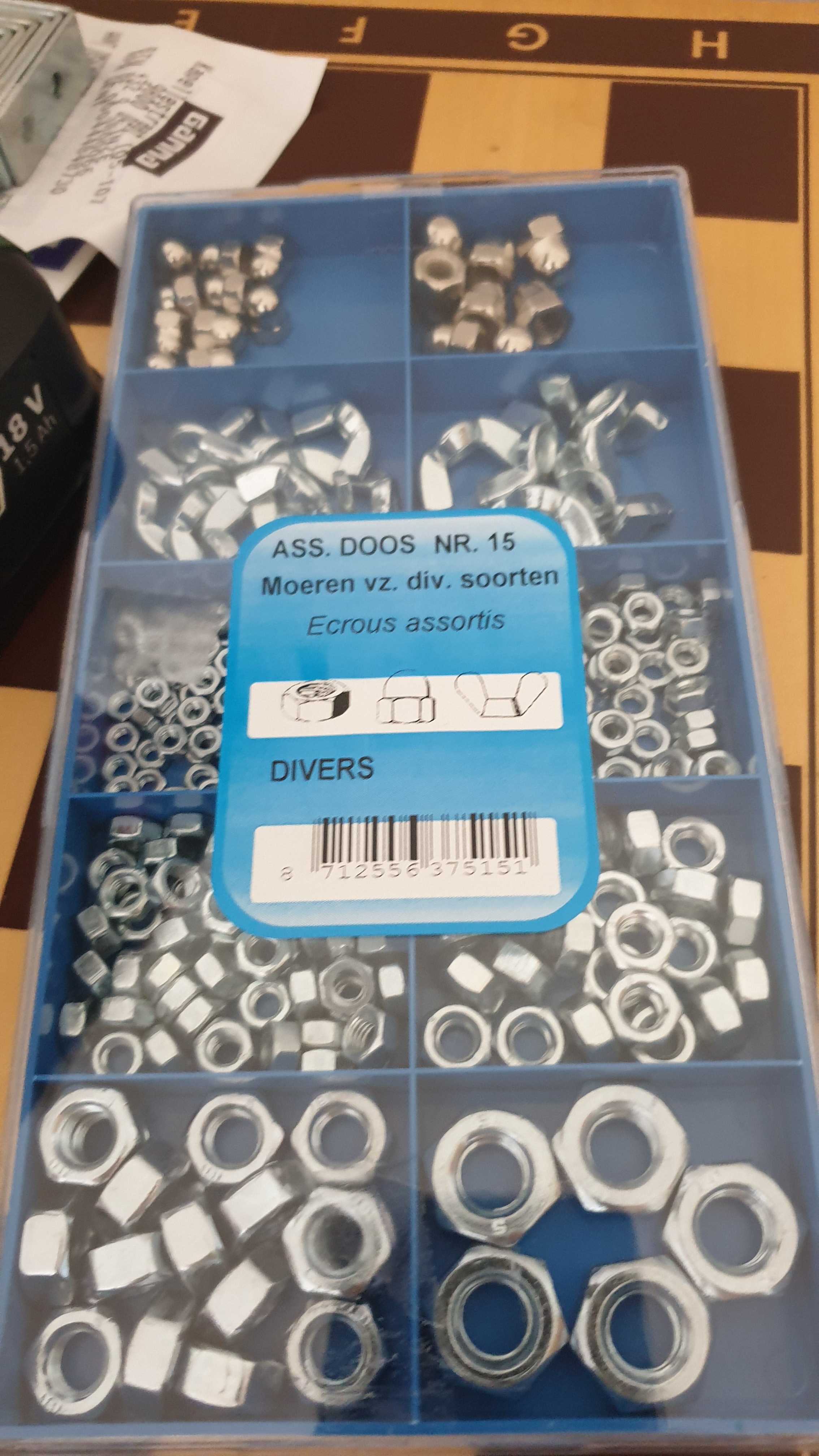
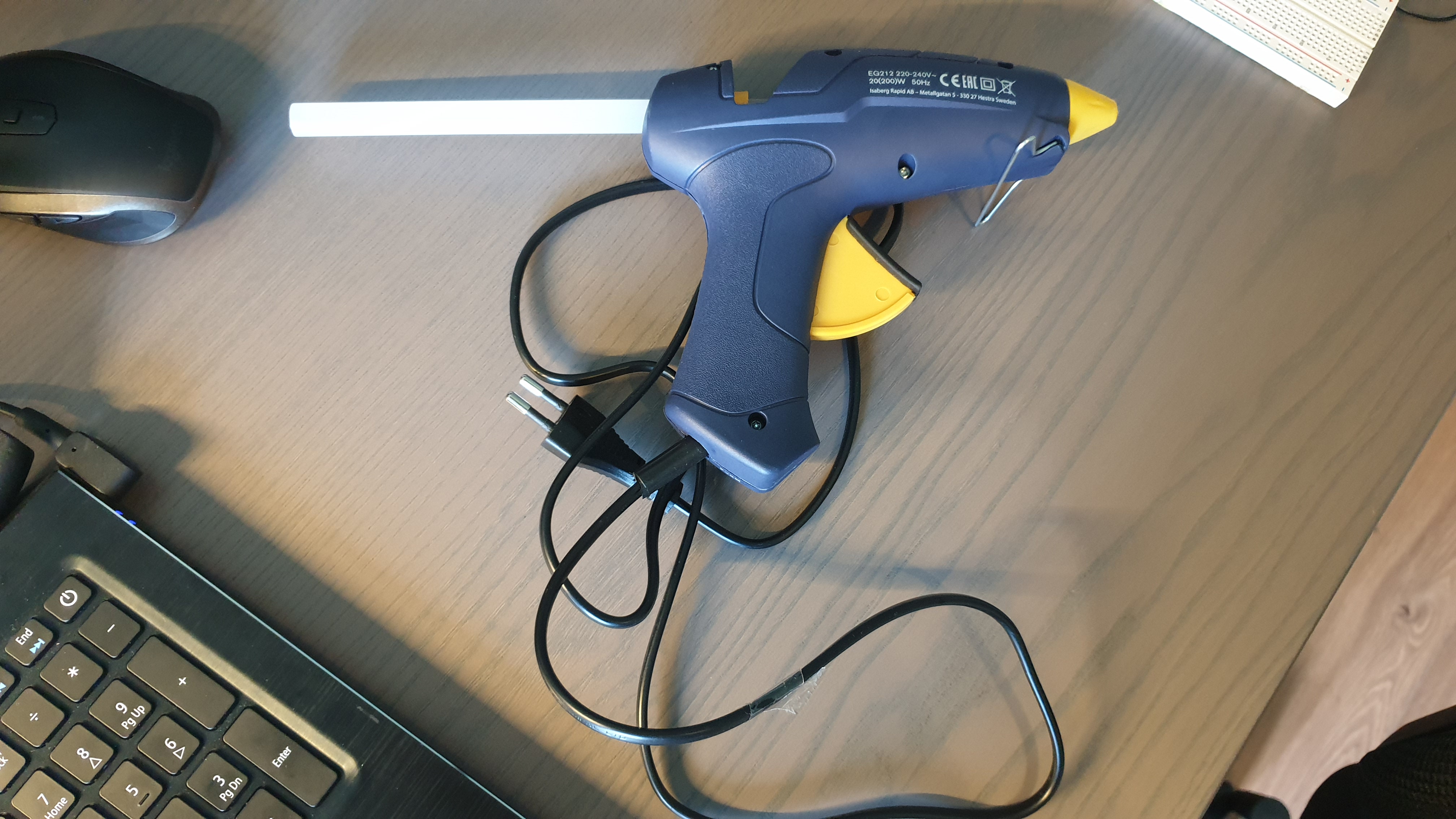
The case can be anything you want. If you want to make a self-contained prototype like mine, there are a few requirements.
-Some cutouts for mounting components trough the front plate
-Some sort of door mechanism
-Enough space on the inside
I used 6mm thick wood. It's very sturdy and perfect if you want to lasercut in it, but mounting the components without having screw come through to the front can be challenging.
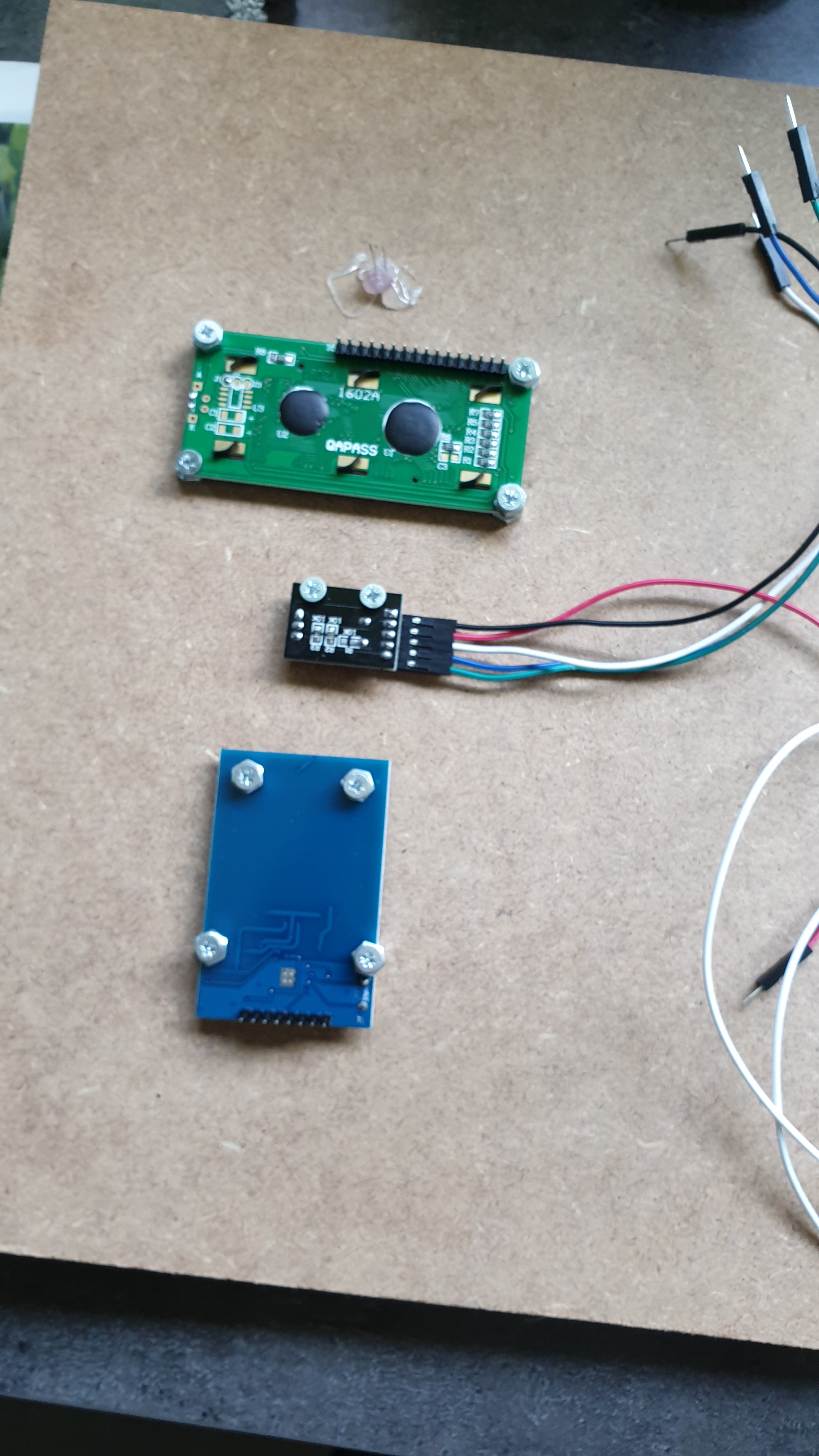
I settled on the screws shown in the picture and then used nuts to make them effectively shorter. I strongly recommend testing how far your screws go on a throwaway piece of the material you're using though, as these parts may vary.
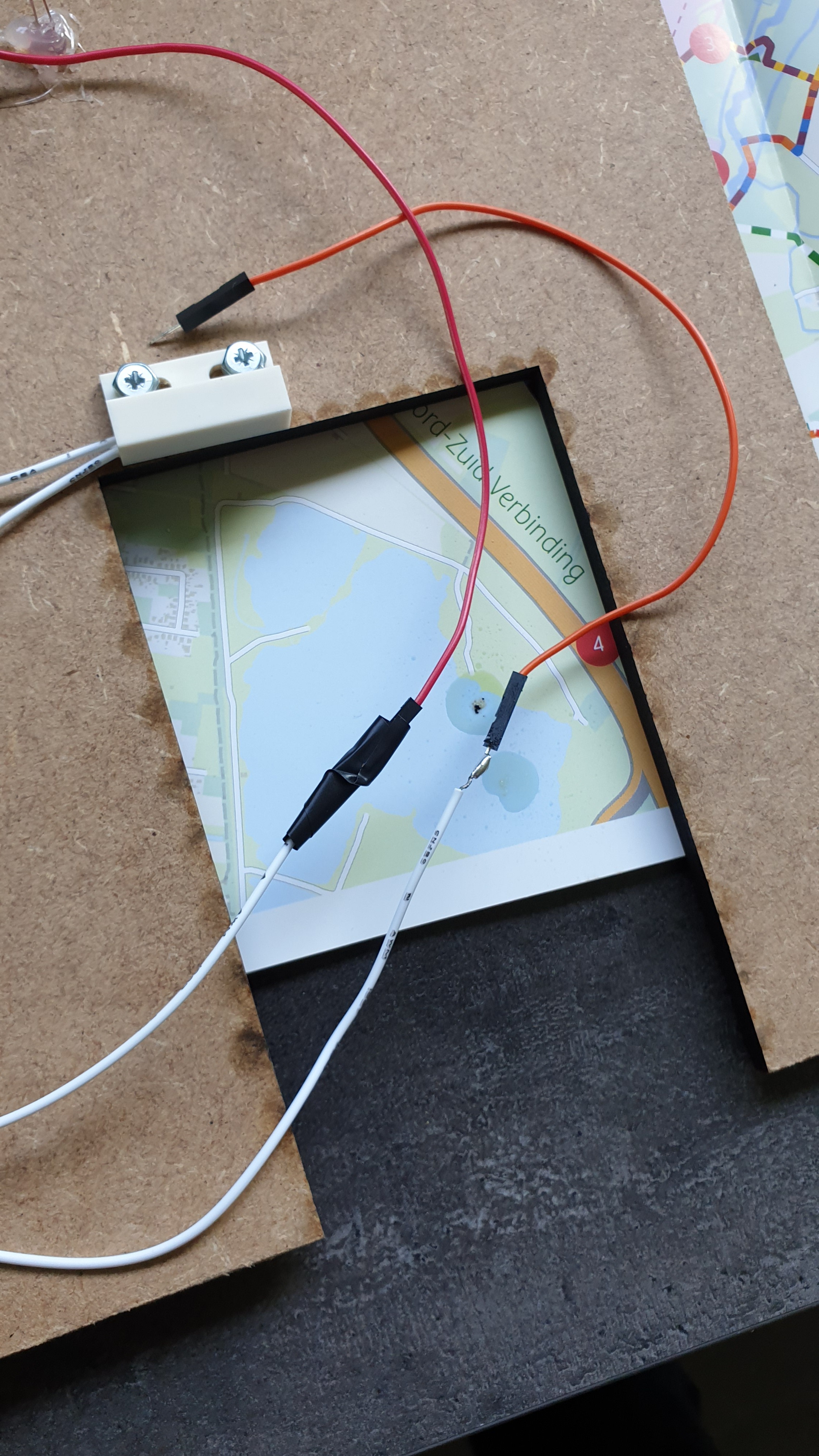
Some parts didn't have good screwholes (keyes-040, hcsr501, leds) so I also used a hot glue gun to fasten these into place. It's not the cleanest solution but it'll do just fine. A soldering iron might not be needed, but I used one to solder better wires to my ada375 door sensor as they came loose too easily.
The parts I mounted to the case are:
-2 leds
-ada375
-hcsr501
-lcd
-rotary ecoder
-rfid reader
The rest is attached to the breadboard. (Mounting the temperature sensor somewhere outside the case may be preferable though)
Some Remarks on My Case
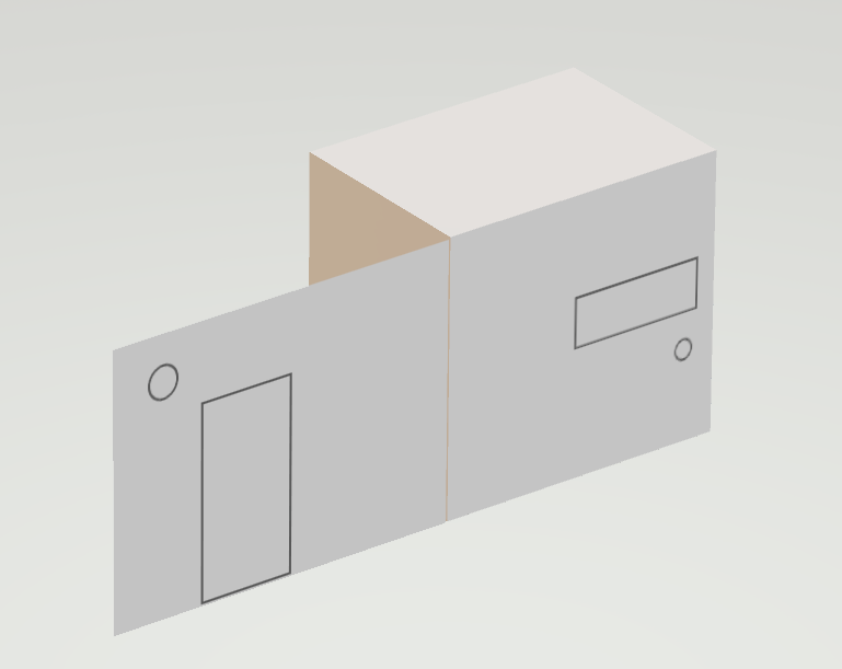

You can find a draft model of the case above. Here are the dimensions:
frontplate: 40.5 x 30 cm
sides of component housing:20 x 30 cm
top and bottom: 20 x 20 cm
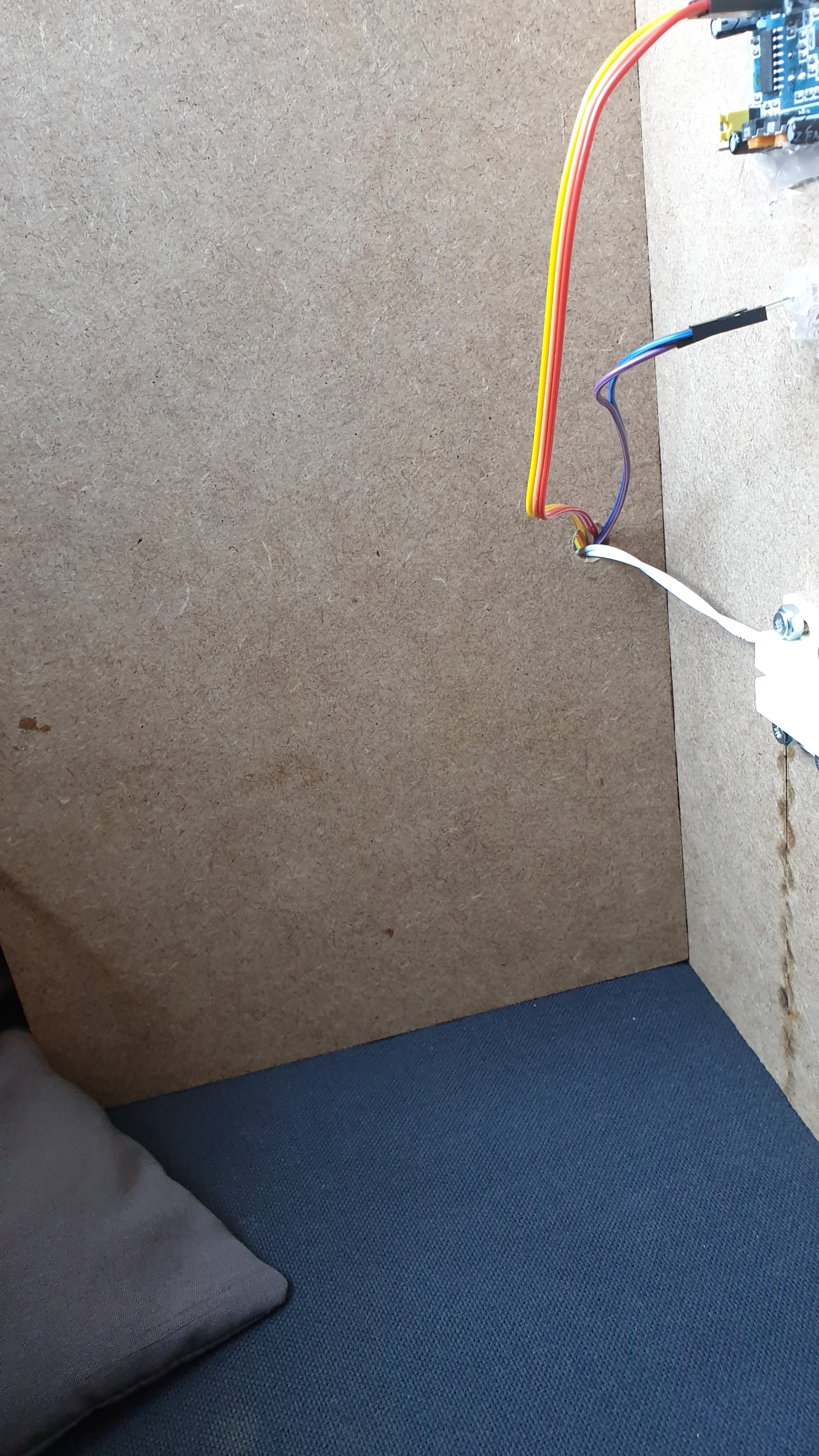
I drilled a little hole in the side to route the sensor wires trough and a bigger one in the back panel for the power and ethernet cables. The openings for the 2 leds in the front were also drilled
One advice: DON'T copy these dimensions! The top plate for me should have been 20.6 x 21.2 cm because I didn't account for the thickness of the wood. And even if that were right, the enclosure where the Pi and components sit, is barely big enough. I didn't account for the extra length of the breadboard power supply, and just got lucky that I could place it in there diagonally.
I suggest using about the same size front plate, and just making the back case a 5 cm wider. There is more than enough space left on the left side to move the door and sensors a bit more to the edge.
Or, you know.. Design your own!
Assembly

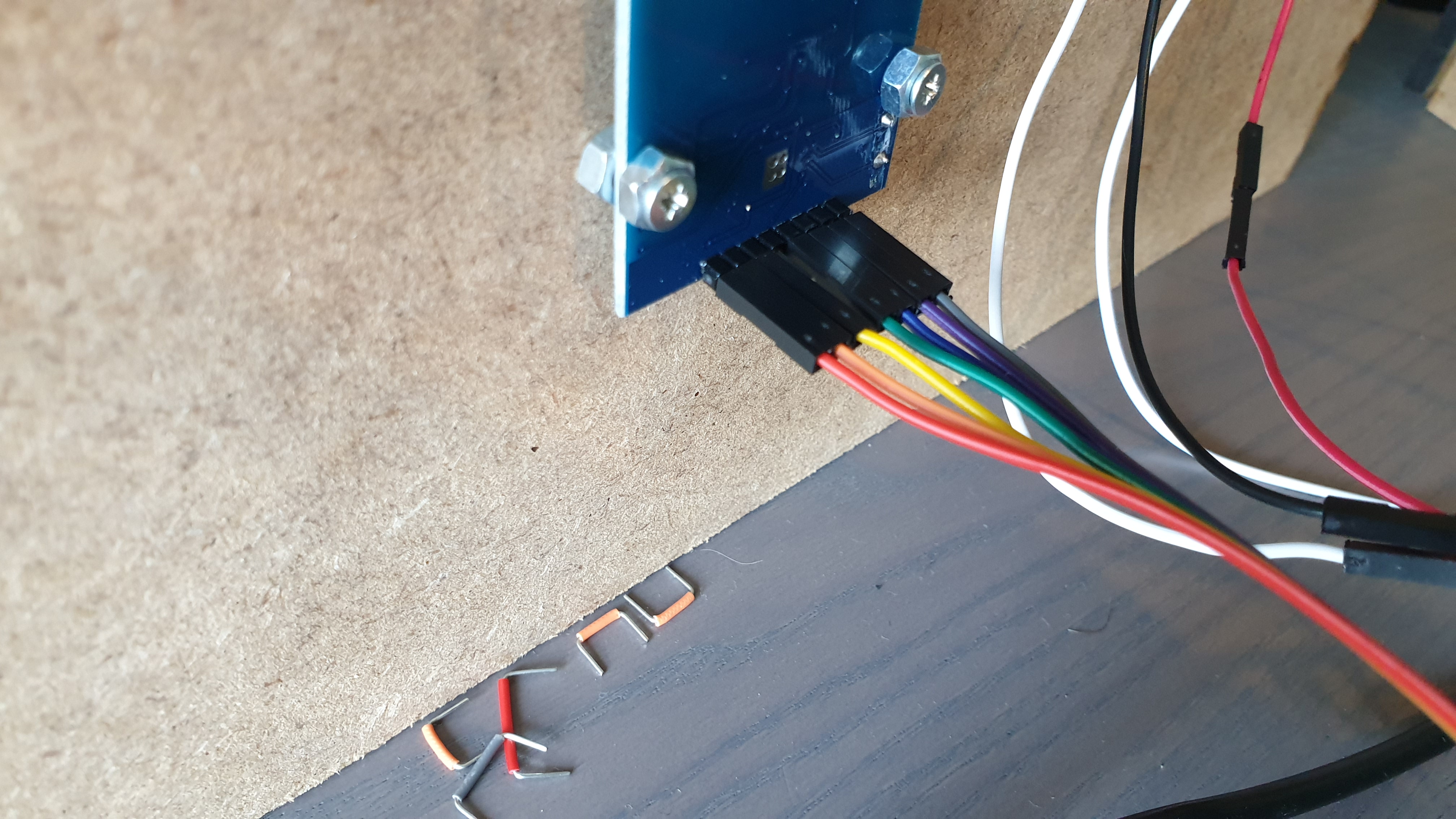
I found working in this order to be the easiest:
1: cut your wood to the right size
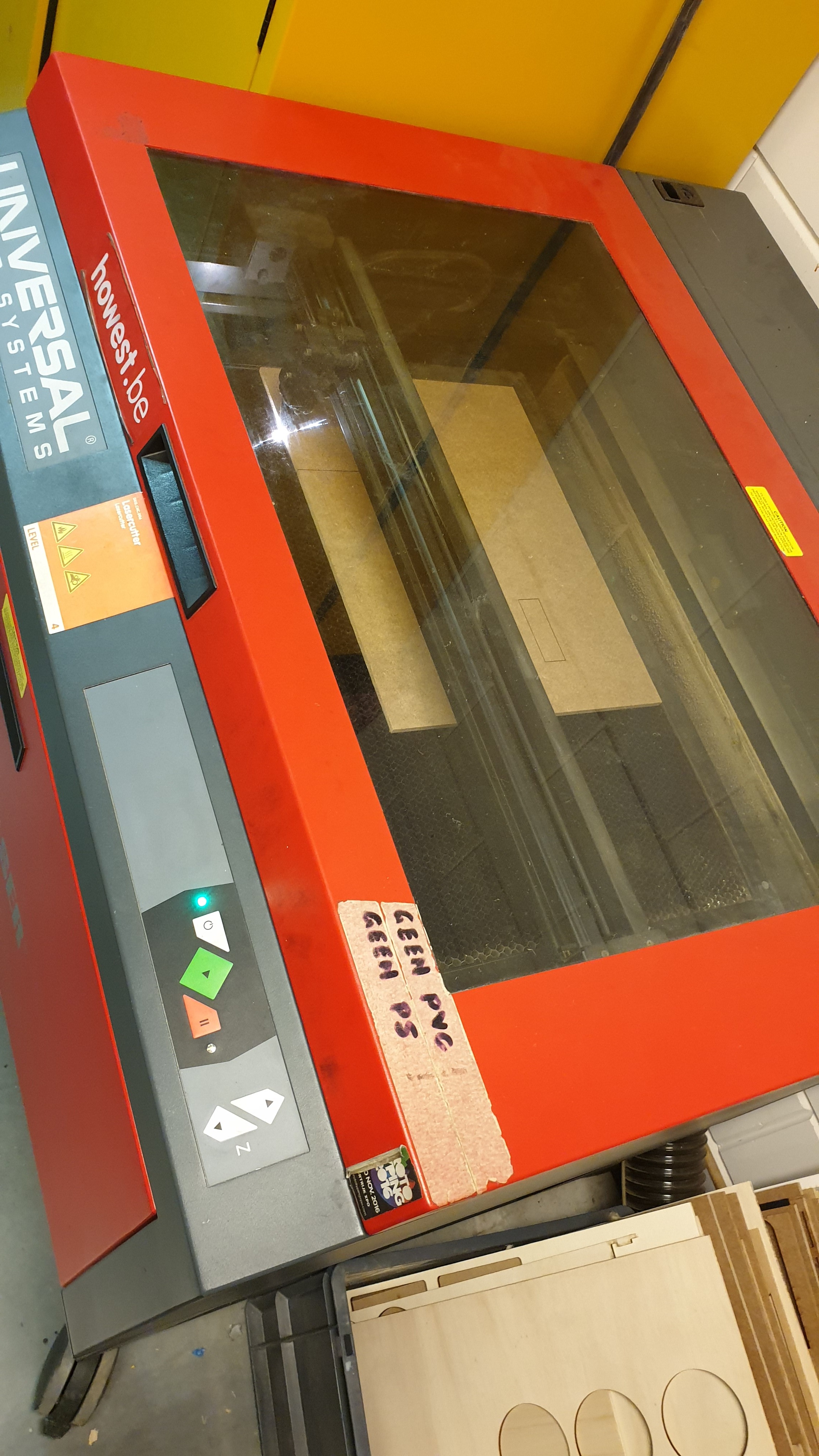
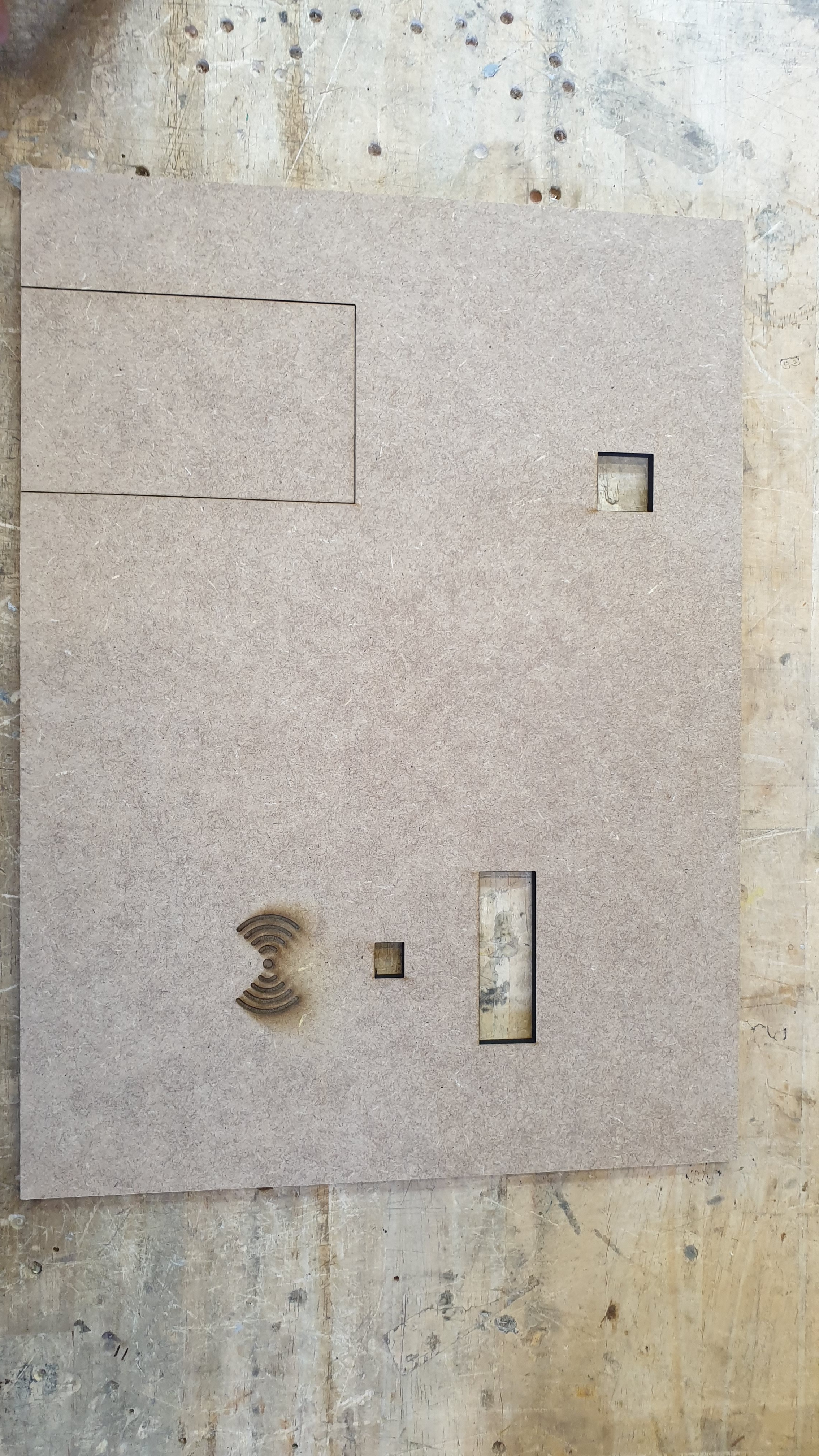
2: take the front plate and make the cutouts for the components (if you want to laser-cut this, the file is attached, you need two extra holes for the leds though)
3: mount the necessary components to the frontplate
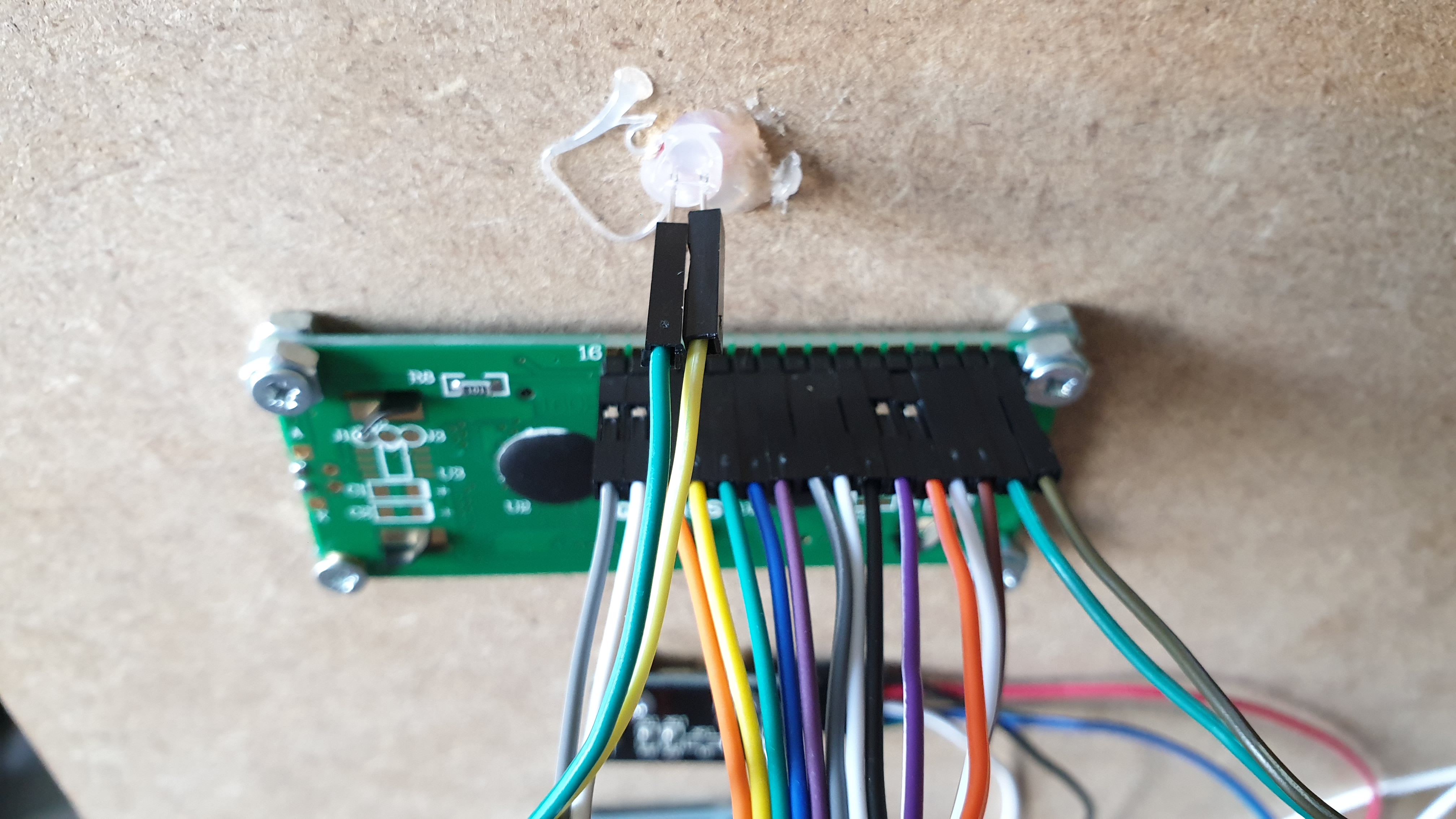
4: Test-connect these components. You better do this while you still have some space to work in. I taped the corresponding wires together to make them in sort of a header. That makes it a whole lot easier to connect them when everything is in place
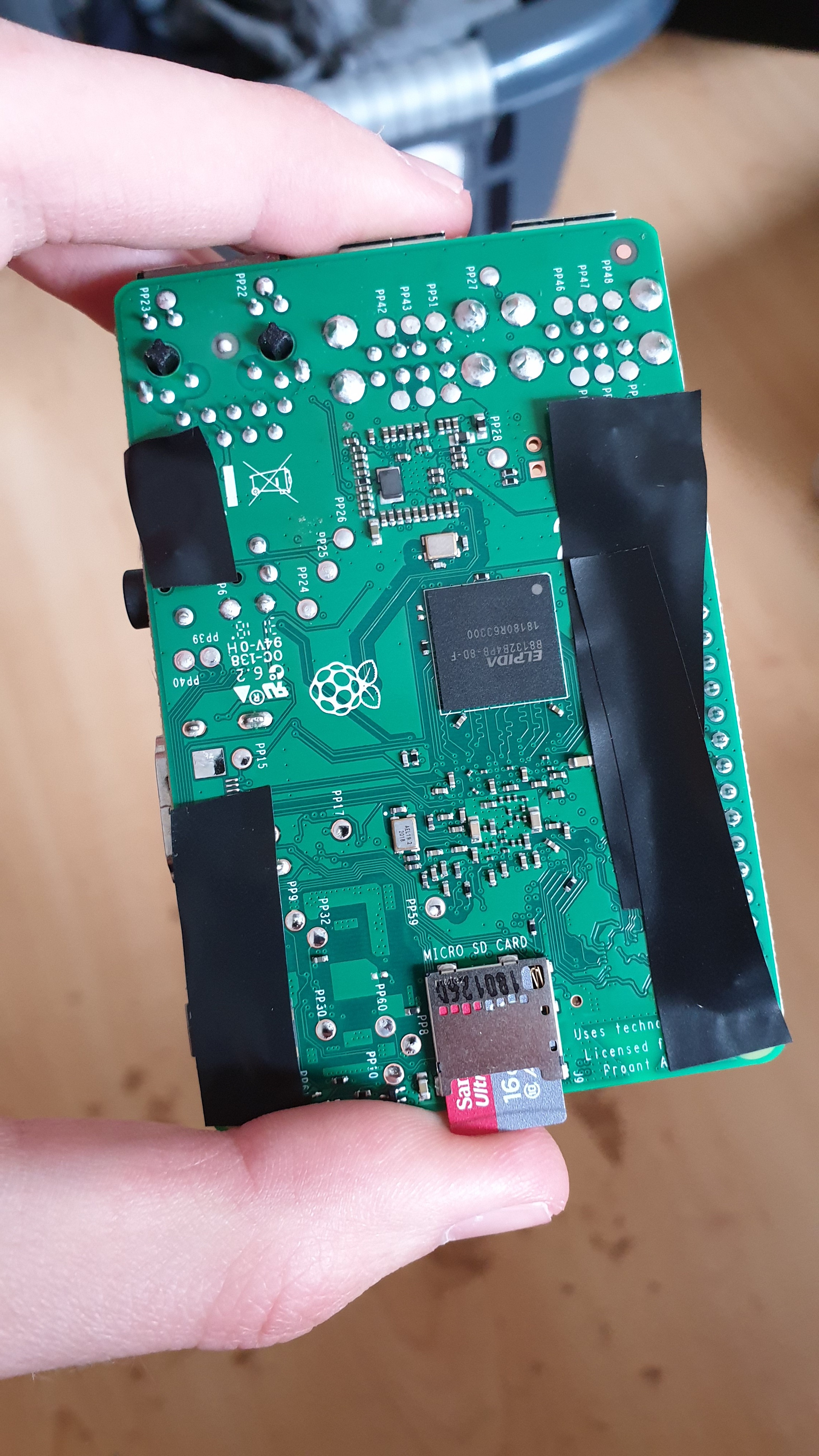
5: mount the raspberry pi to the inside housing (or find another solution for mounting it because it will be almost impossible to remove the sd card) The nuts I used came in contact with metal pins on the Pi so I covered some of the bottom with electrical tape.
More Assembly
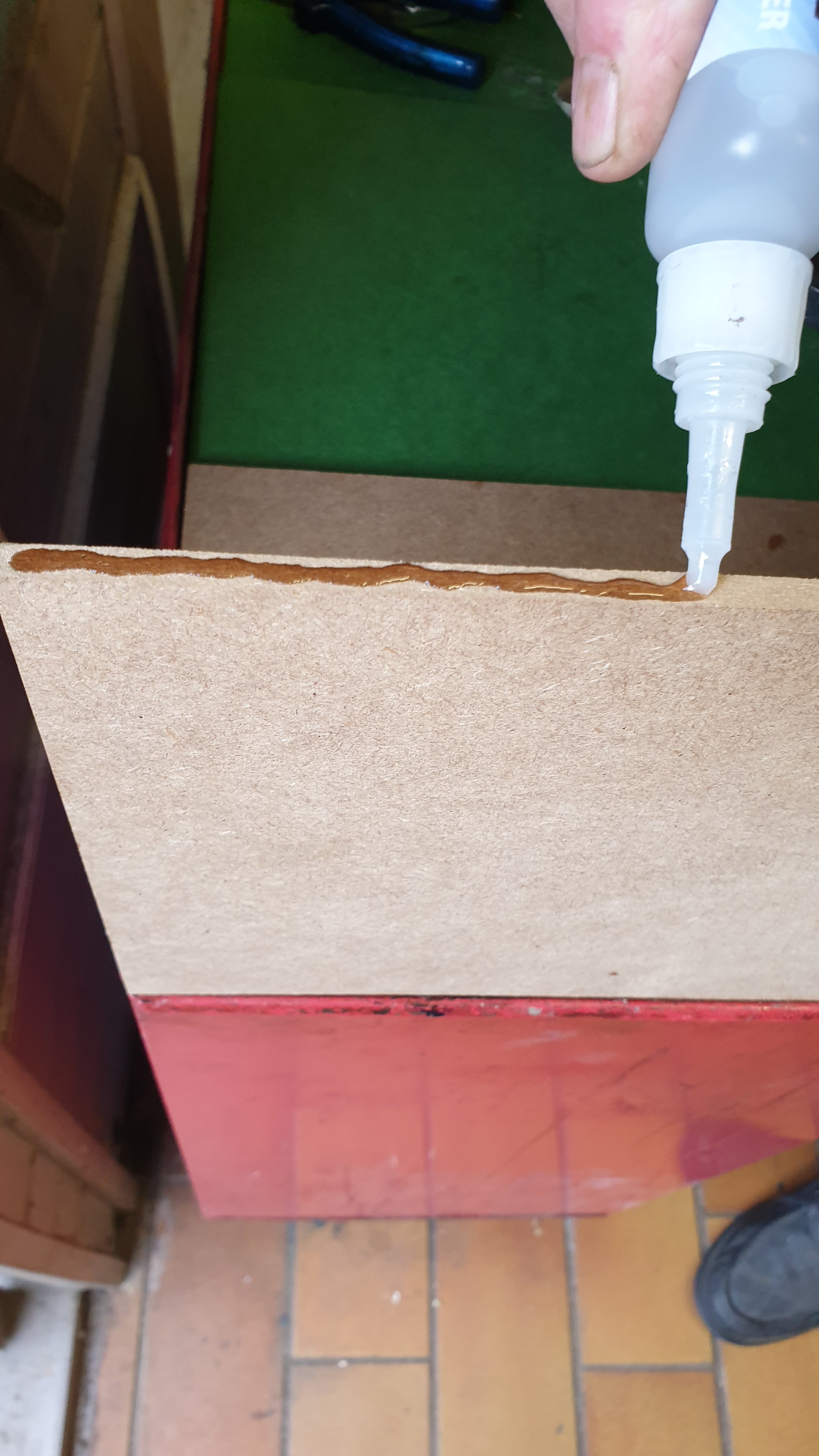
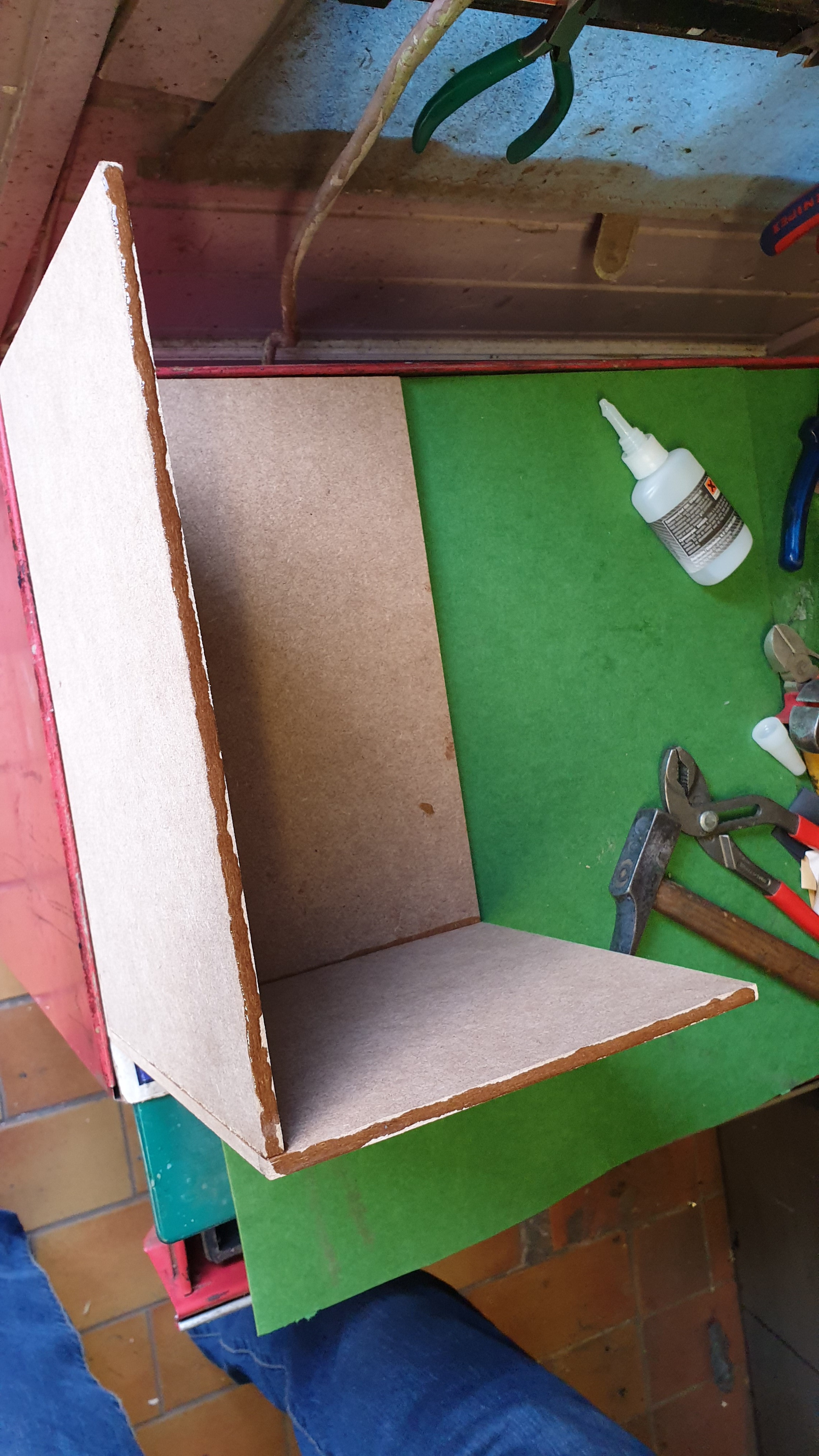
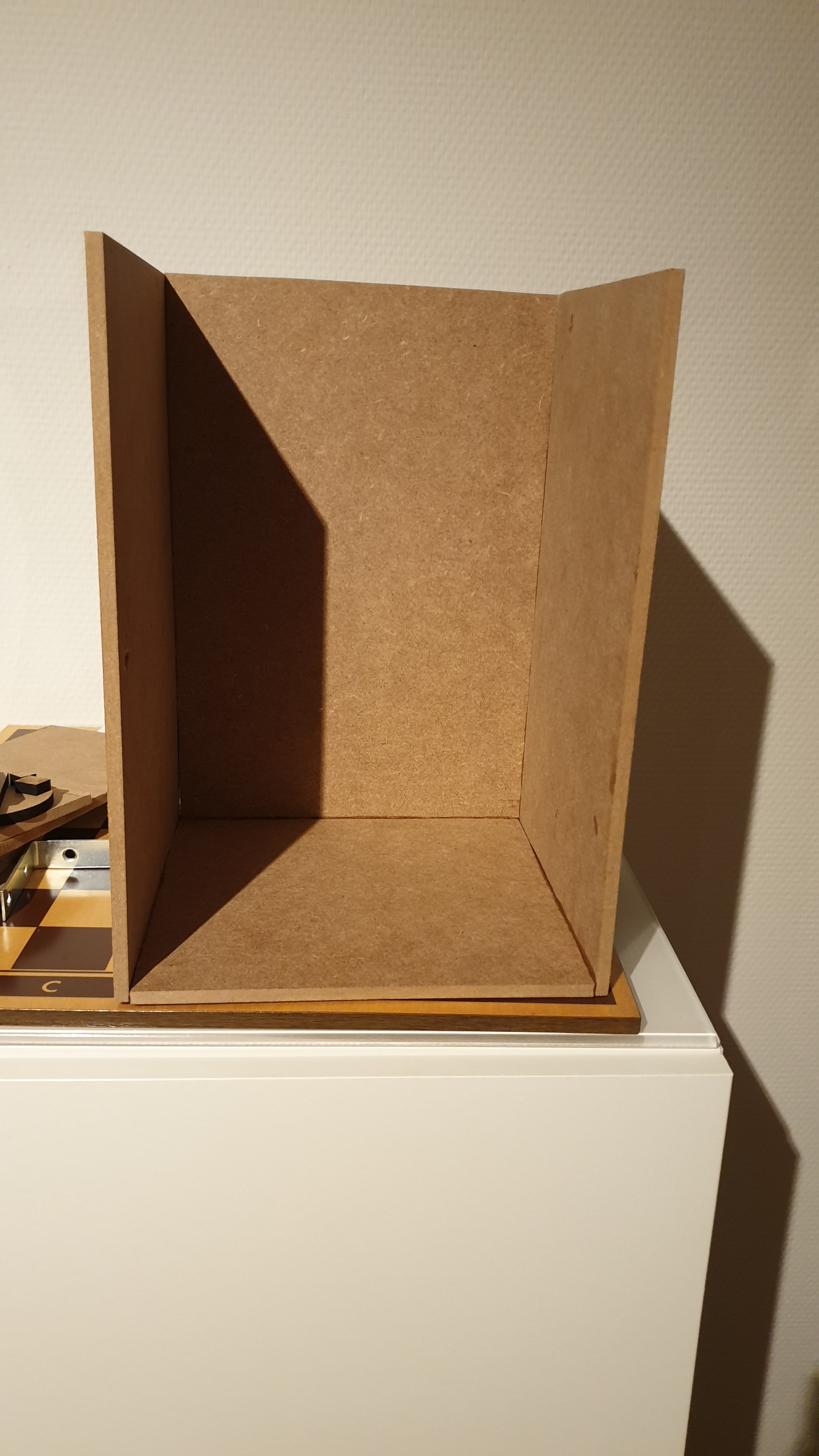
Now put it together (I used very strong wood glue as this wood wasn't to happy with nails or screws in the 6mm thick side)
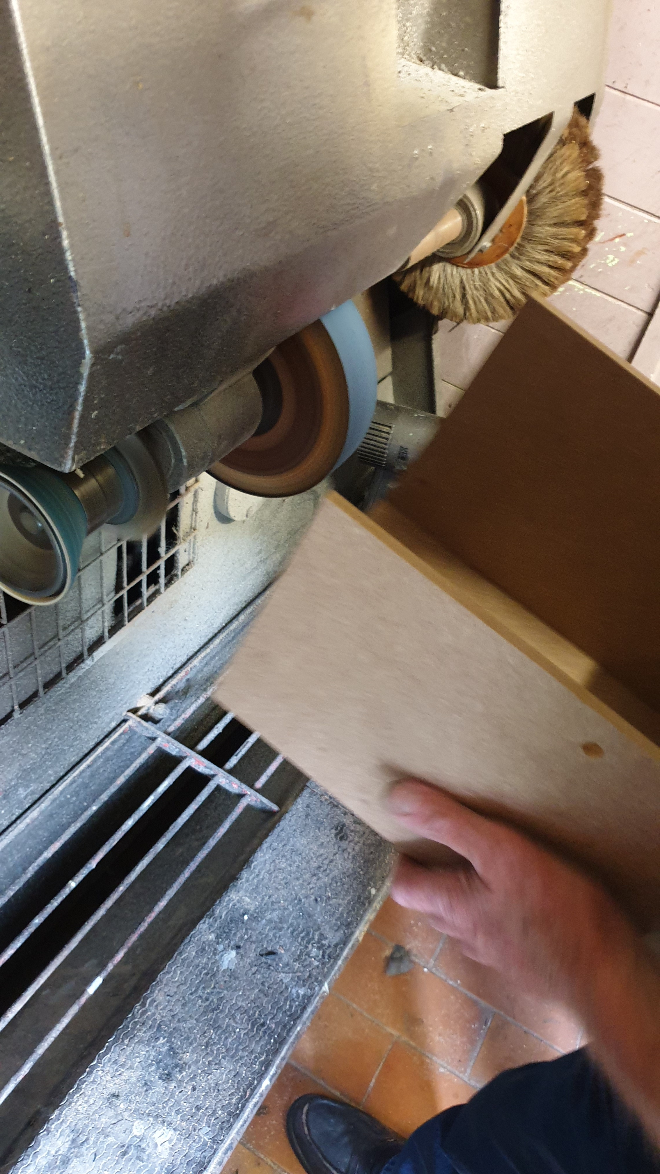
I glued the two side panels of the housing to the outside edge of the bottom plate, and put the back panel on top of the bottom plate, in-between the side plates. This makes it stronger but I did have to grind the top of the backplate as came out 6mm higher than the side and front panels
Connecting
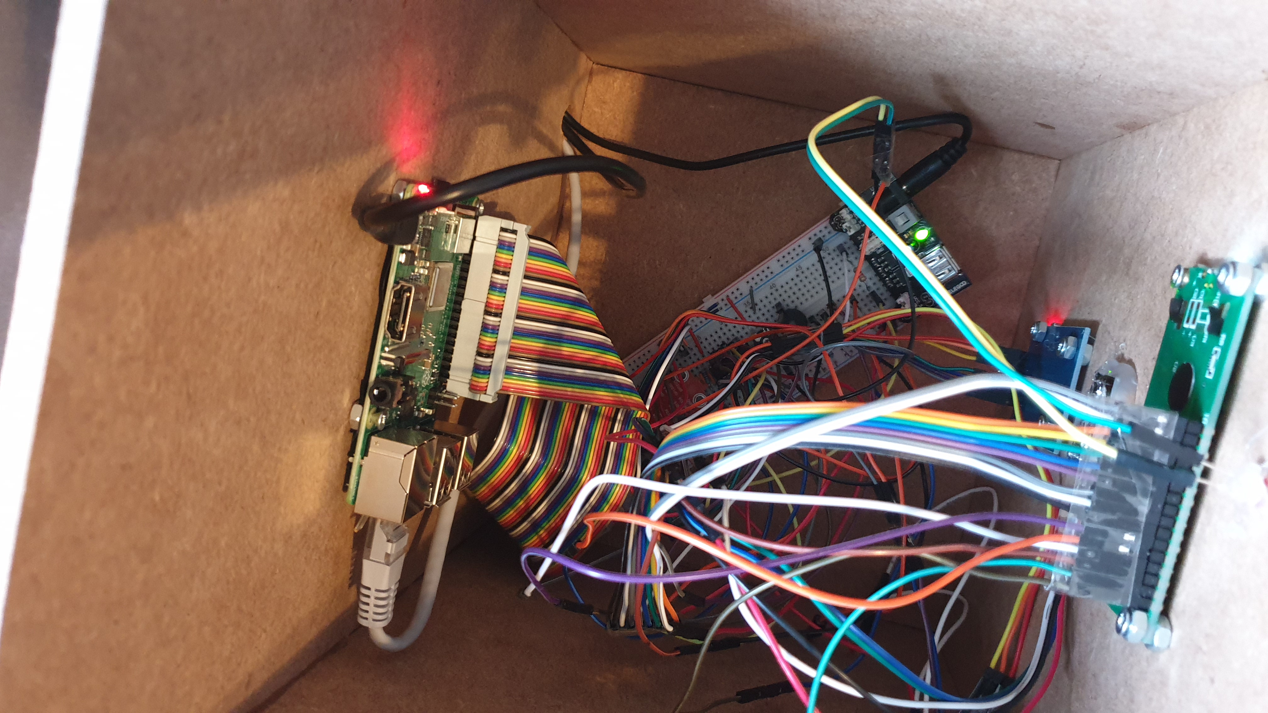
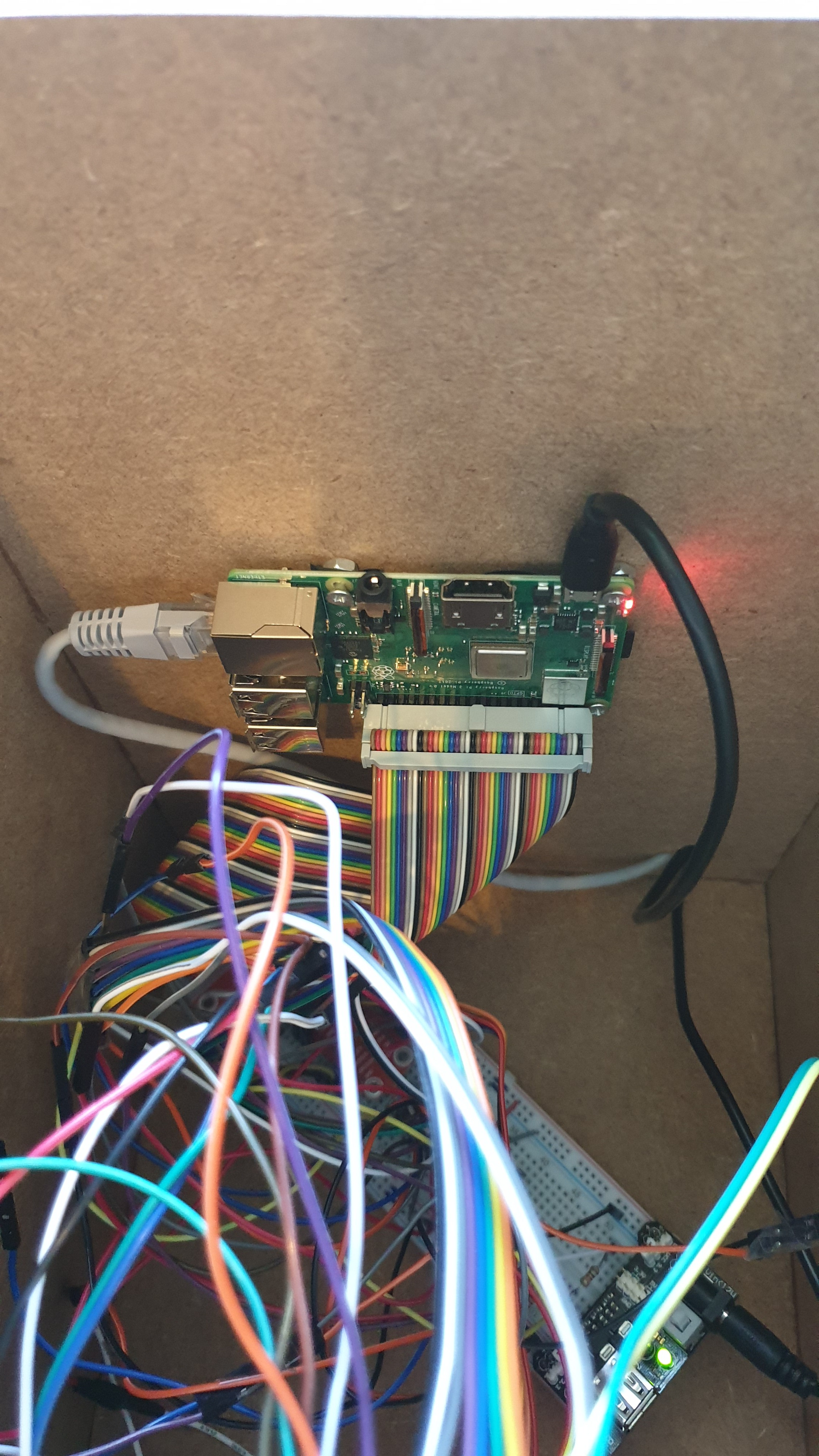
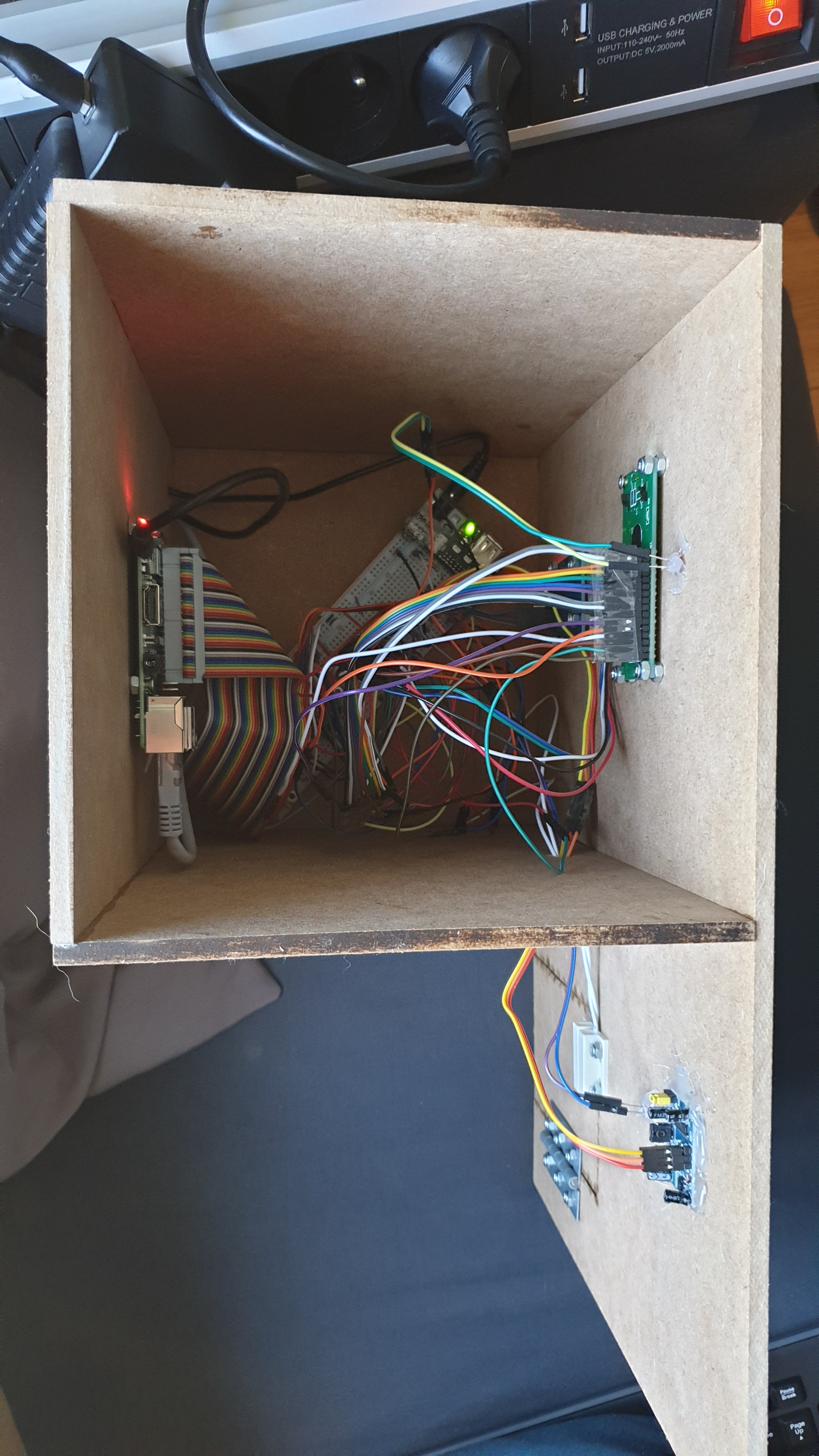
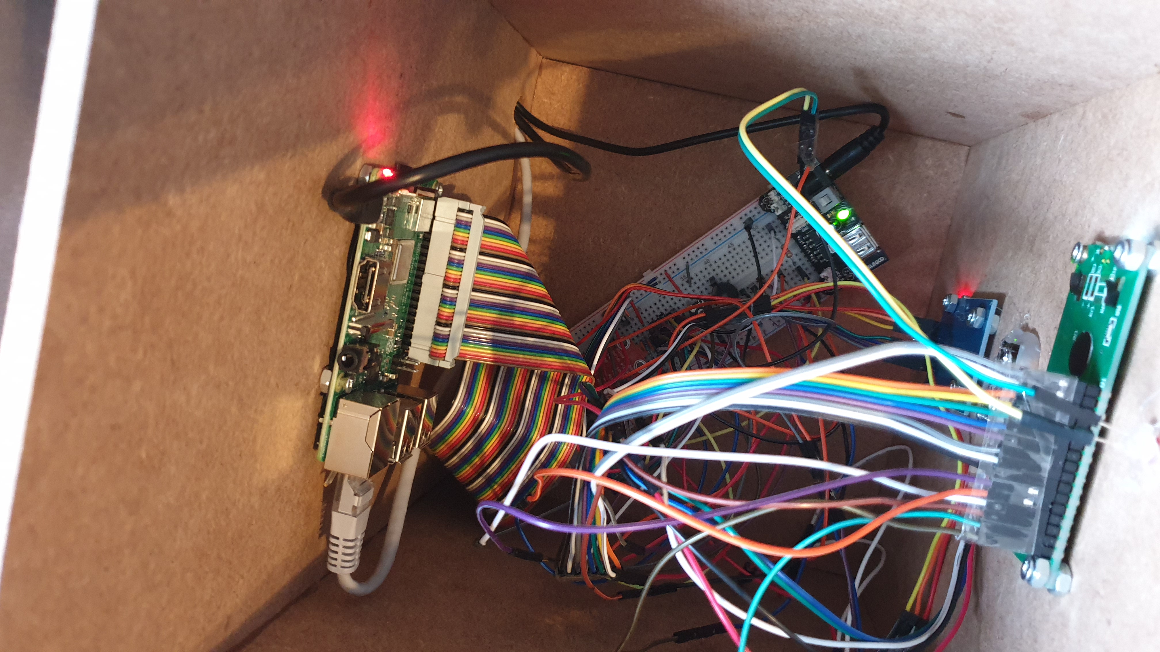
Finally it's time to reconnect the components inside the case. I just dropped the breadboard into place with all the cables attached to it, and then connected the mounted components one by one.
As you can see this really isn't too clean though, so you might find a better way to mount it properly
Software
You will have to add a user to the database if you want to use the rfid reader to arm and disarm the system. Connect to your pi via Workbench, select the Alarmostat database and run the following command:
INSERT INTO alarmostat.user (iduser, username, usertype, userpassword, userrfidtag) VALUES (DEFAULT, '#yourusername', 'user', '#password', '#rfidid')
replace the # with the right values. You can find the rfidid by running the rfidtest.py script from the repository. It'll display the id of your tag: https://github.com/thomasdebiehw/project-backend/b...
To run the program at startup, see the readme: https://github.com/thomasdebiehw/project-backend
You're Ready

It's done! you're ready to protect and temperature control your imaginary house! Have fun and try to add new features to the code!