Airduino
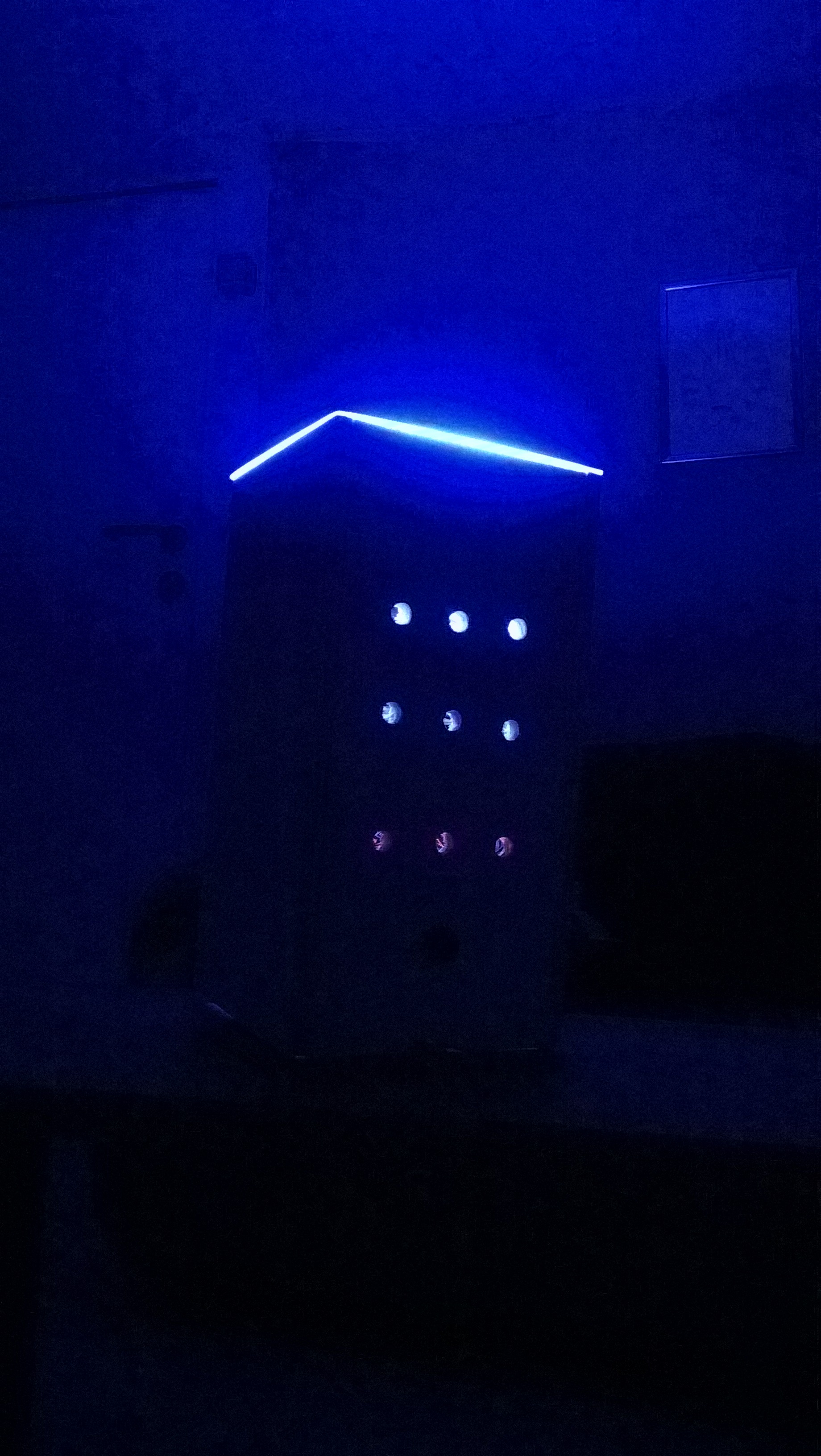
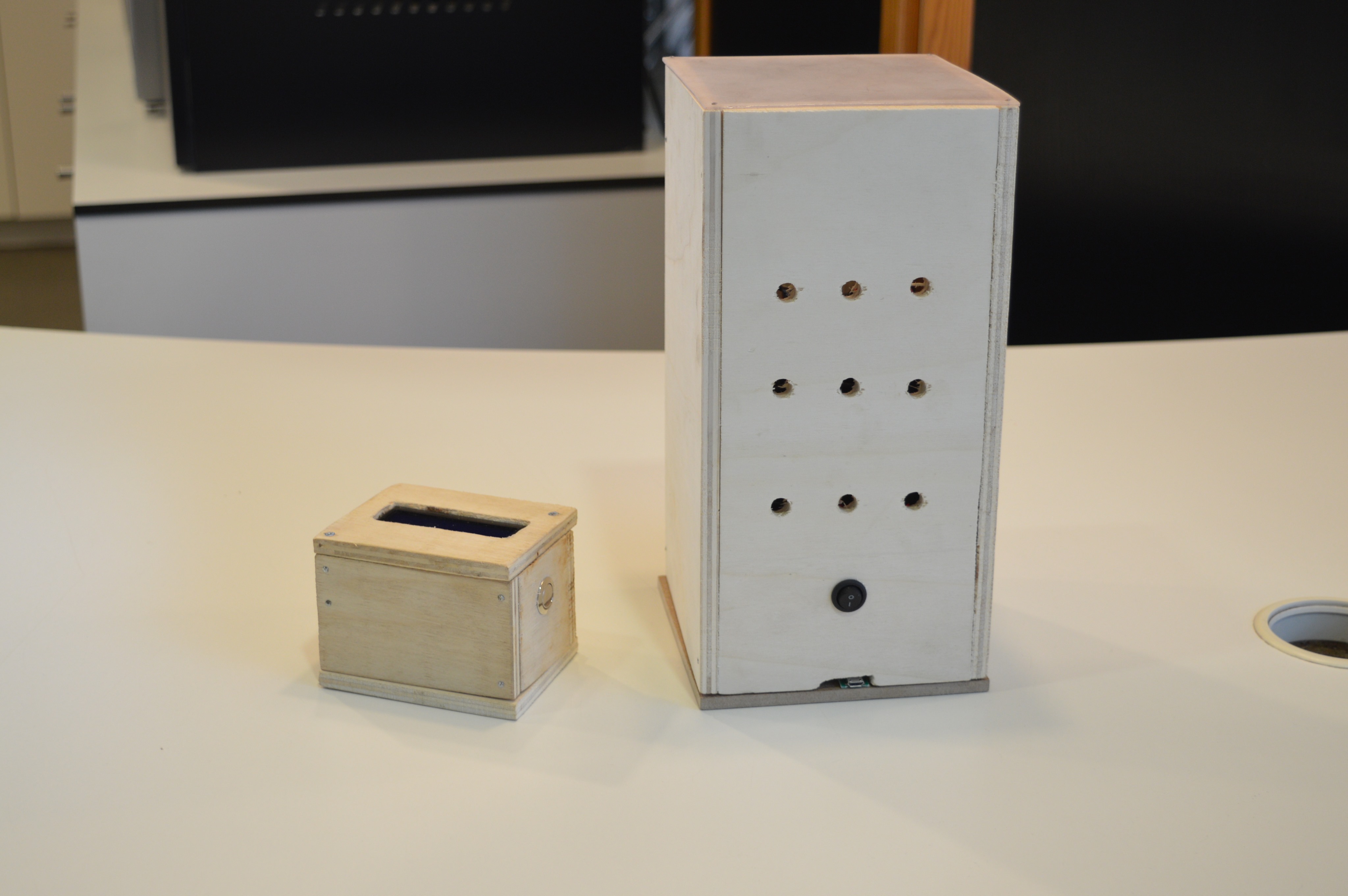
A few words before I explain how I created my Airduino. The whole project is actually a school-based project and because we had a strict time limit a lot of things aren't perfect but the basic functionality works.
So what is the Airduino? Short: it's a fancy wireless air monitor. Long: an Arduino measures the quality of the air, sends all the data to a Raspberry Pi via Bluetooth and stores it in a database. I made a simple website to visually display the data. But the most important thing, it has a powerful controllable RGB led!
What exactly does it measure? Well, I chose to measure the temperature, humidity, air pressure, CO2 and CO. You can measure anything you want, as long as there's a compatible sensor for it.
I've included a detailed list of supplies with links to some of the products I bought.
Supplies
These are all the components I used:
Arduino
Raspberry Pi
LCD display
HC-05, any Bluetooth module will work
BMP-180 (air pressure sensor)
DHT-11 (air humidity sensor)
MQ-7 (CO sensor)
MQ-135 (CO2 sensor)
9W RGB led (3x3W)
XL4015 Step down buck converters (link)(2x)
XL6009E1 Step-up boost converter (link)
MH CD42 battery board (link)
18650 Battery cell (4x)
4 Bay 18650 battery holder
BC337 transistors (5x)
Resistors (1 Kohm (5x), 10 Kohm)
Switch
Button
Micro USB to DIP adapter
Wires
Perfboard
Heatsink (from an old computer)
Arduino Circuit
.jpg)
.jpg)
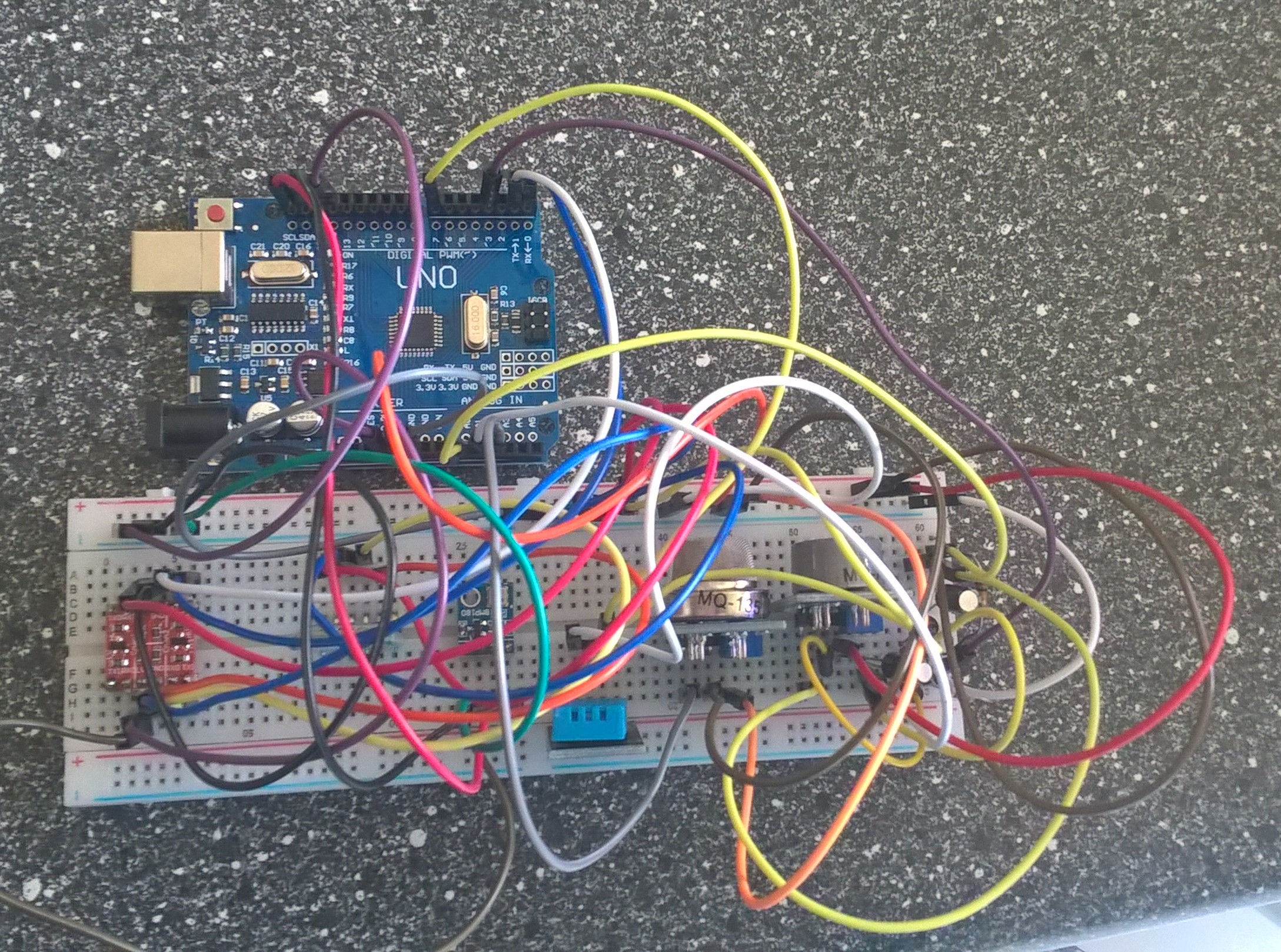
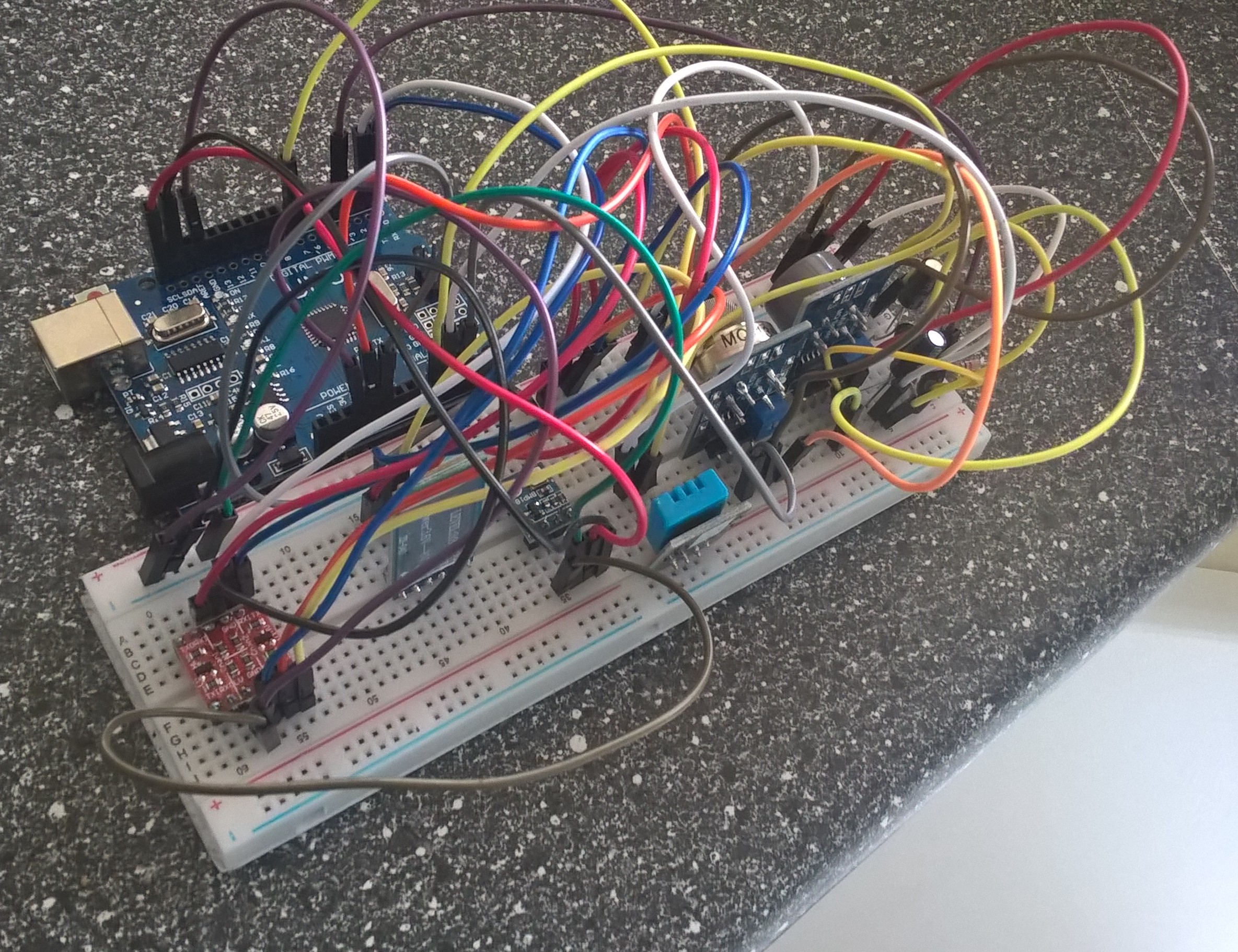
The most difficult part is the part of the Arduino because it handles basically everything.
In the included schematics you can see, well, the schematic. It might look big and difficult at first but it's fairly easy. I first build the whole circuit without the circuitry for the led, on a breadbord to see if it all worked. Afterwords I soldered everything of perfboard, I tried to at least.
Most of the sensors are fairly straight forward except the MQ-7. This sensor is, for my experience hard to incorporate in the project. I followed one of the only good guids I could find and it seemed to work if I only connected that sensor. If I connected the other sensors it acted weird so I had to do some manipulation of the code, more on that later.
Arduino Code
If you have build your circuit on a breadboard then you are able to test most of it. Connect your Arduino to a pc and upload the included code. If you disconnect the tx and rx pins you can send commands via the Arduino IDE Monitor. If you send 'BMPTemp' you should get a response if you did everything right.
Downloads
Raspberry Pi Circuit
I added a display to my Pi to display the IP-address the site is hosted on. the most difficult thing was figuring out the right pins.
Raspberry Pi Code
The first thing you have to do is configure the onboard Bluetooth. I did everything using the command line, it can be done using a GUI but I will not cover that. I assume you know the basics of a Raspberry PI and Rasbian, the operating system.
It goes as follow:
Step 1: connect to your Pi via SSH, I use Putty.
Step 2: Type the following commands in the terminal:
- 'sudo bluetoothctl'
- 'power on'
- 'agent on'
- 'scan on'
Step 3: Now wait until the HC-05 is discovered, you need to power it on.
Step 4: Now will have to pair and trust the device, type the following commands:
- 'pair xx:xx:xx:xx:xx:xx', with the mac address of the HC-05 module in the place of the x'es.
- 'connect xx:xx:xx:xx:xx:xx', but this will most likely give an error.
- 'trust xx:xx:xx:xx:xx:xx'
Step 5: Now that the module is paired and trusted we need to bind it to a serial port. This can be done with the following command: 'sudo rfcomm bind 0 xx:xx:xx:xx:xx:xx', again with the x'es representing the mac-address of the HC-05 module. Normally if you look in '/dev' you should see 'rfcomm0', if you don't try rebooting.
The problem is now that you have to manually execute that command every thing you boot the Pi. To do that automatically I added the command to '/etc/rc.local' before 'exit 0'. Now it will automatically bind the module.
Now that you have configured the Bluetooth you can run the code I included. Beware that I have put a MariaDB database on my Pi, I will not cover how to set that up, I will only include a model of my database and a dumbfile. If you want to run the code without the database and the website I included a simple program to do so.
Copy the content of the zip file to your Pi and run them with the following command: 'python3 airduino.py', assuming you are in the same folder. If your Arduino is powered on and the tx and rx pins are connected you should see some messages about inserting data into database. If you want to automaticaly start the program add this line to '/etc/rc.local': 'python3 /<pathToArduino.py>/arduino.py', replace <pathToArduino.py> with the actual path.
For the website, I installed an appache server to host the website. Copy the files from the zipfile to '/var/www/html/'. Now if you go to the IP-address of your PI you should see the website and data if everything worked correctly.
Building a Case and Soldering
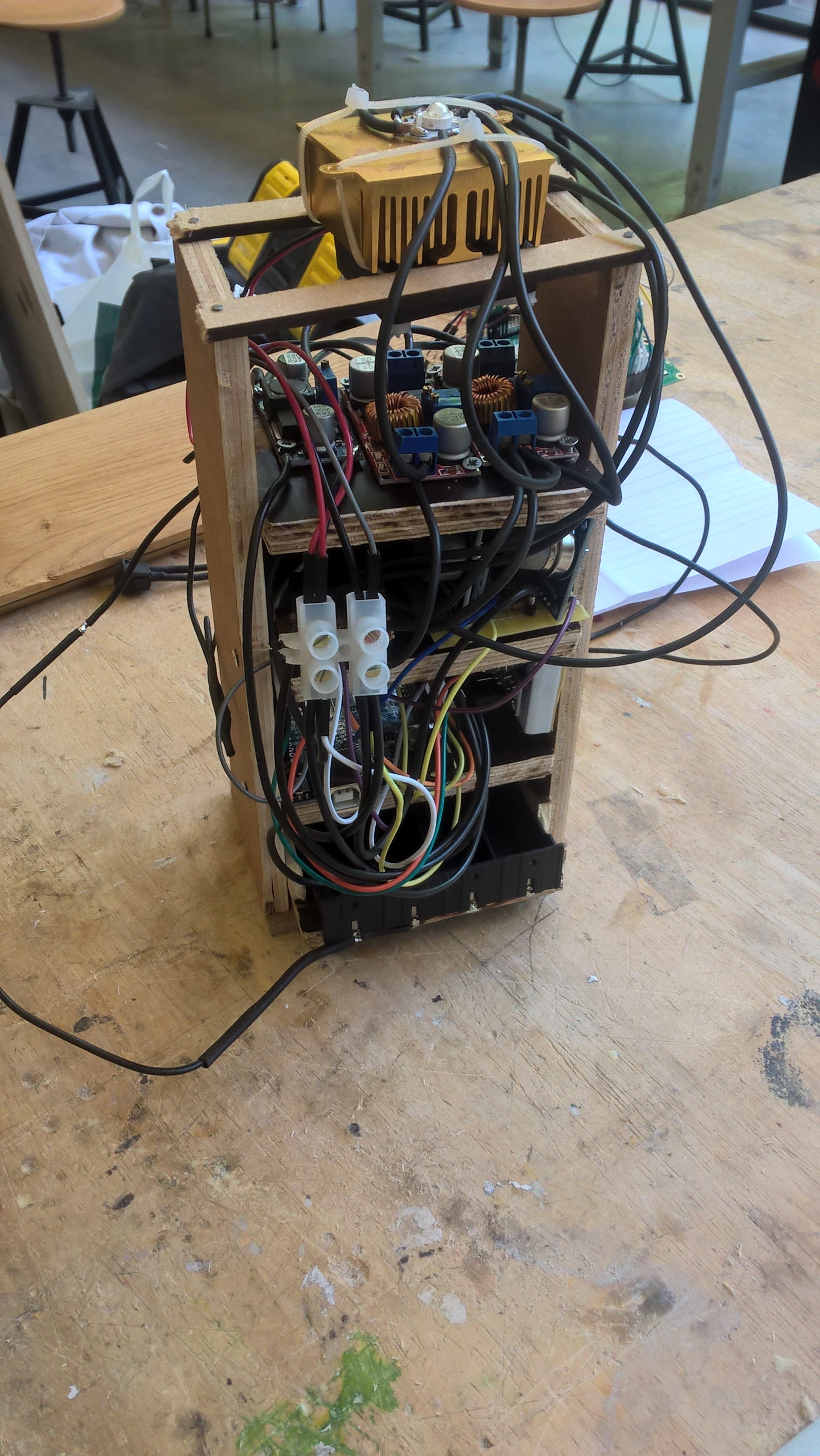
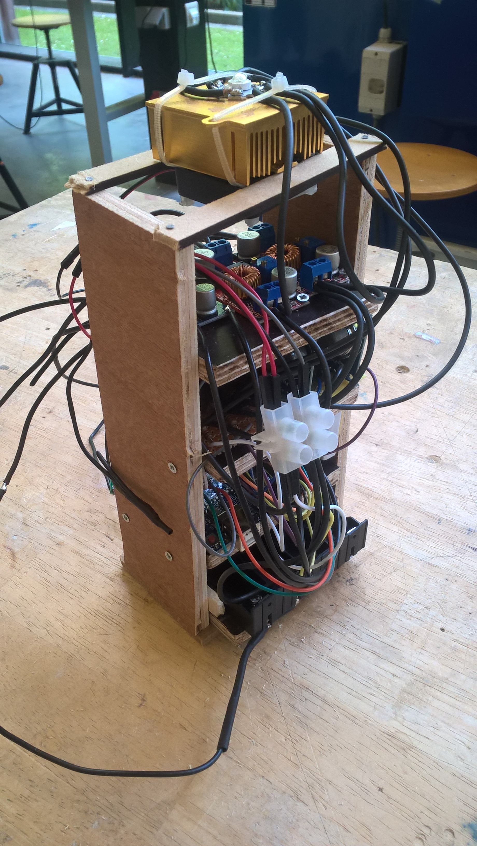

Arduino
Now that everything works, except the led, it's time to put everything in a nice case. I decide to make a tower where all the components are connected to, and surround that by a simple case.
But first I soldered all the components to perfboard and attached some wires for Ground and Vcc. I put mostly one or two components on one piece and placed them around the tower.
The battery holder has longer wires and isn't fixed in place, it can slide in and out to change cells.
At this point I placed the drivers for the led on the last level of my tower. I turned down the output voltage of the drivers to 2.2 for the red led and 3.2 for the green and blue led. I attached the led to my heat sink and my fan with zip-ties. Then I used some wood to hold it in place.
I connected most of the Ground wires and Vcc wires using screw terminals.
Make sure you're make your base plate big enough so the outer case lines up nicely. The outer case is just a squire box out of wood. On top I put some transparent plastic witch I sanded a little bit to make the light softer. I also added power button.
Raspberry Pi
For the Raspberry Pi I just made a simple wooden box with the LCD on top and the button on the side.
Finale
After you soldered everything and build your enclosure it's time to do the final testing. Power everything on and visit the website, if all went right you should see some live data.
About the batteries:
If you use more then 1 battery in parallel you need to make sure their voltage levels are the same, or close to.
Github:
Here is a link to my Github repository where all the up-to-date files are located.