Advanced Traffic Light System
by Jeet756868 in Circuits > Arduino
232 Views, 0 Favorites, 0 Comments
Advanced Traffic Light System


Once upon a time, the incredible concept of a 'traffic light' was invented to make street life a lot more simple. Who knew with the development of our minds and technology, that same concept could be built onto a breadboard with some creative adjustments.
Welcome back to yet another Instructable that shows you step by step on how to create your very own advanced and fun Arduino traffic light system. It works almost just like a regular traffic light you'd see on a day to day basis, but with even more - that's essentially the gist of it.
You might not be able to grasp it right away, but how one goes about building this project is actually much more easier than you think. But, how does this so-called advanced traffic light system even work? Great question. Essentially, like any other traffic light, the basis of it operates the exact same way. When the push button is pressed, the entire system turns on, therefore, the green LED turns on for about a few seconds, followed by yellow, then red. The red LED will stay on with the sequence on pause, however, if the distance sensor senses a distance less than 5 inches while it's on, it will trigger the seven segment display to start counting backwards to 0 from 9. When '9' is displayed, the RGB LED will turn red, indicating it is the farthest away from the green LED to signal "Go" and you must remain at a full stop. When '5' is displayed, the RGB LED will turn blue with an indication of the halfway mark, and when '0' is displayed, the RGB LED will turn green. Immediately after it turns green, the countdown will end and the RGB will turn off. The green LED will then turn on and follow the same exact sequence of the traffic light. If the pushbutton is pressed again, the entire system turns off.
Supplies

.jpg)


- Arduino Uno
- Arduino Cable
- Long Breadboard
- 1 x Pushbutton
- 1 x Red LED
- 1 x Yellow LED
- 1 x Green LED
- 1 x RGB LED (Common Anode)
- 6 x 330Ω Resistors
- 1 x 10kΩ Resistor
- 7 Segment Display
- Distance Sensor
Placing the Components Onto the Breadboard

1 - The LEDs and 330Ω Resistors
The best idea would first be to plan out where you're going to place the green, yellow, and red LED that essentially serve the main part of the purpose. The initial plan is to have enough space between your LEDs and other components, similar to the example above, so that later you will be able to put them into a miniature traffic light prop as recommended - Because that's the best part.
- First, place the red LED onto your breadboard, then follow it by the yellow LED, and then green. This will later be taken and put into an upright prop.
- Then of course, connect a 330Ω resistor to the negative (cathode) of each led.
2 - The Pushbutton
Placing the pushbutton onto the breadboard is a rather simple process, but also a precise one. Once you have placed it onto the breadboard, follow these steps to ensure it is wired properly:
- Connect the 10kΩ resistor to the first terminal of the pushbutton (left side), and place it into the negative rail on the breadboard - This process connects the pushbutton to ground.
- Then, take a red wire and attach it to the second opposing terminal of the pushbutton, then connect it to power.
3 - The Distance Sensor
Wiring the distance sensor on the breadboard is a process that doesn't require much of an explanation. There is a label that says 'Vcc' on the far left which is what you use a red wire to connect to power, and as well as that, a label that says 'Gnd' on the far right which is what you use a black wire to connect to ground.
4 - The RBG LED
In a simple essence, the RGB LED only needs one 330Ω resistor, the rest of its legs will be later wired to the Arduino.
- In this case, the RGB LED in use is a common anode, therefore the 330Ω resistor will be connected to the positive rail on the breadboard (power).
- This leg is fairly easy to differentiate from the others - it is the longest leg of the RGB LED.
5 - The Seven Segment Display
Place the seven segment display onto the breadboard like the example in the image above and follow the simple two following steps:
- First, connect a 330Ω resistor to the common of the seven segment display, which is then connected to power.
- Then, connect another 330Ω resistor to the corresponding common on the opposite side of the seven segment display, which is also connected to power.
Last but not least, the final step is to use a red wire to connect each side of the positive rails to each other, and a black wire to connect each side of the negative rails to each other. This ensures that power and ground is equally transmitted throughout the entire circuit.
And there you have it, you are officially done with wiring the components onto the breadboard portion and can now move on to the next part. Even more wiring.
Begin Wiring the Entirety - Arduino


With the intricate wiring throughout this project, mainly due to the seven segment display, it is crucial to follow each pin connection carefully in an organized manner. Therefore, this step will guide one through the specific Arduino pins designated for each component.
For now, regarding the 3 LEDs, simply connect your wires to them and the designated pins. The steps on how to go about making the actual traffic light prop will be introduced later on.
(3D wiring is optional)
The LEDs:
- For this instance, the red LED is connected to pin '13' using a red wire
- The yellow LED is connected to pin '6' using a yellow wire
- And lastly, the green LED is connected to pin '7' using a green wire
The Pushbutton:
- Connect the corresponding terminal to where the resistor is connected to a digital input pin with a coloured wire of choice, in this case pin '12' is used.
The RGB LED:
- The RGB has 4 specified pins: Red, Anode, Green and Blue. Click here for image of RGB, follow Common Anode
- The Anode is connected to power with a resistor
- The red, green, and blue pins all must be connected to PWM (Pulse Width Modulation) pins.
Connect the red pin to pin '11'
Connect the green pin to pin '10'
Connect the blue pin to pin '9'
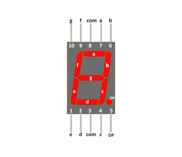
The 7-Segment Display
A 7-segment display consists of 7 segments, labeled a, b, c, d, e, f, and g. This step is quite the process, however, this image (click here) and specifications below will surely make it make sense:
Since most of the pins were used for the other components, majority of the seven segment display will be using the analog pins (A0 - A5) instead.
Connect pin 'a' of the 7-segment to Arduino pin 'A5'
Connect pin 'b' of the 7-segment to Arduino pin '2' (This is the only one that will not be using an analog pin)
Connect pin 'c' of the 7-segment to Arduino pin 'A3'
Connect pin 'd' of the 7-segment to Arduino pin 'A2'
Connect pin 'e' of the 7-segment to Arduino pin 'A0'
Connect pin 'f' of the 7-segment to Arduino pin 'A4'
And finally, connect pin 'g' of the 7-segment to Arduino pin 'A1'
For the wiring, it is recommended that you use the same colour for the entire seven segment display like the image above.
There you have it, the wiring portion is complete and we can now move on to actually getting the project working.
Breaking Down the Code - Declare Variable Names and Pins

This is the easy part of the code. Declare each variable for each component and which Arduino pin they use like so. You can use whichever variable name you'd like, or simply just use the same one's provided.
Breaking Down the Code - Void Setup

.png)
The first part of void setup states which specific components are declared as input or output. The output devices are always declared as output, and the input as input, simple as that. Regarding the distance sensor, 'trig' is declared as output, and 'echo' is declared as input.
This is the second part to void setup:
This portion of the code is what defines the functions to control a 7-segment display and shows the digits 0–9. Each digit is represented by a specific combination of segments turned on or off (LOW or HIGH). It essentially works in the opposite way of how one would think for it to. 'HIGH' in this case, turns a segment off, and 'LOW' to the contrary turns it on.
Take 'void zero' for example:
- Segments a, b, c, d, e, f are on (LOW).
- Segment g is off (HIGH).
This lights up the shape of the digit "0" on the 7-segment display.
This is the third and last part of void setup:
The function 'void setColour' allows a colour on an RGB to be set by specifying values for the red, green, and blue components (each ranging from 0 to 255). By varying the red, green, and blue values, you can create any colour.
- Red, green, and blue are integers representing the brightness levels of the red, green, and blue LEDs.
- And as priory mentioned, each value can range from 0 (fully off) to 255 (fully on).
Lastly, Serial.begin(9600); is the command that opens up a serial port and will allow you to later on print your values.
Breaking Down the Code - Void Loop Part 1
.png)
.png)
The following code does not include the function for a pushbutton.
Now, this first portion for void loop includes both the functions for the LEDs and the distance sensor.
The function 'digitalWrite (green, HIGH);' is what turns the green LED on, and 'delay(5000);' leaves it on for 5 seconds. Then, 'digitalWrite(green, LOW); ' turns the LED off. As the code goes on, the same thing occurs for both the yellow LED (for 3 seconds instead, hence delay(3000);) and the red LED all in that specific order. However, with the red LED, there is no 'delay' or 'digitalWrite (red, LOW);' that turns it off - this is essentially because the red LED will stay on while the rest of the code operates. Later on in the code after a specific sequence, the green LED will turn on again. But we're not there yet.
Before we move on to the basis of how the term 'advanced traffic light' comes in, the second image provided shows the function used to measure distance with the distance sensor. The distance sensor essentially operates by emitting an ultrasonic pulse or sound waves and measures how long those sound waves take to bounce back from an object - hence this code being the setup needed to make that happen. As well as that, it also calculates the distance in inches.
- Serial.println (inches); allows the serial monitor to print the distance in inches.
Breaking Down the Code - Void Loop Part 2
.png)
.png)
Congratulations, you have made to the very last steps of the complete code. This is the section in void look that will do all the advanced main work at the 'red light'. If you're read the introduction, I'm sure you now have a bit of a grasp on what exactly this project does. When the light turns red, the 7-segment display will start counting down from nine. At 9, the RGB will turn red, then it will turn blue at 5, and once the countdown reaches zero, the RGB will turn green. This code does exactly that in the most simple manner.
This part of the code performs a countdown sequence (from 9 to 0) as mentioned using a 7-segment display and an RGB LED. It is only triggered when an object is detected less than 5 inches away from the distance sensor.
'if (inches < 5) {'
- This is an if statement and remains as the main trigger condition, the sequence should trigger because of this function (However, if you would like to remove the distance sensor as an easier method, the code operates without this statement and the sensor as well)
7- Segment Display
- The functions nine();, eight();, seven();, six();, etc., control the 7-segment display to show numbers from 9 to 0.
- 'delay(1000)' means that each number is displayed for 1 second
The RGB LED
- The RGB changes colours depending on what number the seven segment displays
- setColour(255, 0, 0); sets the RGB to Red.
- setColour(0, 0, 255); sets the RGB to Blue.
- setColour(0, 255, 0); sets the RGB to Green.
- setColour(0, 0, 0); turns the RGB off.
The sequence first shows 9 displayed on the 7-segment. This is when the RBG turns red, delay (1000) means it waits for one second. When numbers 8, 7, and 6 are displayed on the 7-segment, the RBG is off - 'setColour(0, 0, 0);'. When the 7-segment displays number 5, the RBG turns blue - 'setColour(0, 0, 255);'. Numbers 4 through 1 also have the RBG off, and when the 7-segment display shows zero, the RBG turns red - 'setColour(255, 0, 0);'.
The very last part of the code within the second image then turns the red LED off after the sequence ends, and turns the green LED on again. The entire sequence repeats itself in a loop.
The Entire Code
The Traffic Light Prop


This fun step can be done however you like, therefore, I will only go into it briefly.
You will need:
- Cardboard
- A Glue Gun
- Glue Gun Sticks
- Scissors or An Exacto Knife
- Black Paint and A Paint Brush
- Soldering Iron and Solder
- Cut out 4 miniature rectangles from the cardboard, small and big enough to fit all 3 of the LEDs. (Try to make them as equal in size as possible).
- Paint them all black.
- Then, stick your LEDs through what you'd see fit as the front piece, red at the top, yellow in the middle, and green and the bottom - Just like a traffic light.
- Now, you are going to bend the legs of the LEDs downwards, connecting the cathodes to the resistors you placed on the breadboard.
- Solder the anode of the LEDs using a soldering iron to their designated wire colour and re-connect them to the Arduino pins.
- Since you now have your LEDs prepared, carefully glue the other pieces of cardboard onto the main one together in a somewhat 'box' or 'cube' like shape with your glue gun.
- Cut out another piece of cardboard, this one smaller than the rest and in a square shape, then paint it black as well.
- Finally, glue that last piece on top of the others to close your traffic light off.
And that's it - You have officially made it to the end of this Intractable. I hope you've given this project a shot and enjoyed making it to the fullest.
Who wouldn't want to make their own traffic light system?
A Video Demonstration

