Advanced Hexagonal Mesh in Freecad
by ancienthart in Design > Software
22676 Views, 45 Favorites, 0 Comments
Advanced Hexagonal Mesh in Freecad
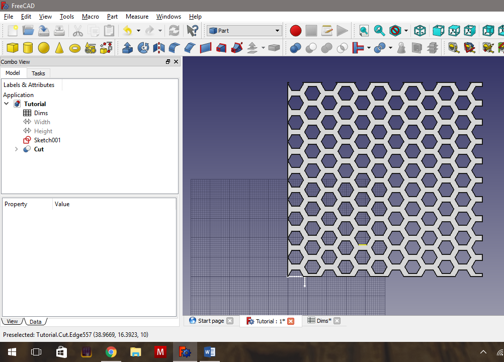
The following is a tutorial for making a hexagonal grid in Freecad, that is parametrically controlled and suitable for 3d printing. What we want is a Freecad file that allows us to type in one measurement for the size of the hexagonal voids, and the thickness of the walls between the two hexagons, and Freecad will calculate the final mesh for us automatically.
If you just wanted to make a single hexagonal grid, you could do it faster than the method outlined below. The reason I’m presenting it this way, is because this tutorial will demonstrate the following advanced Freecad features:
- Parametric modelling using Freecad spreadsheets.
- How to use constraints in Freecad sketches.
- How to link geometry between different sketches (so you can ensure that two parts are the correct distance between each other).
- How to use the Draft Workbench in Freecad to make measurements, including a trick to link those measurements to the actual geometry, enabling measurements to be adjusted as you change your model.
- How to use the Array Draft tool in Freecad to make regular repeating patterns, and finally,
- How to use the Part tools to do an Extrusion and a Boolean Cut.
Adding Parametric Spreadsheet - Steps 1&2
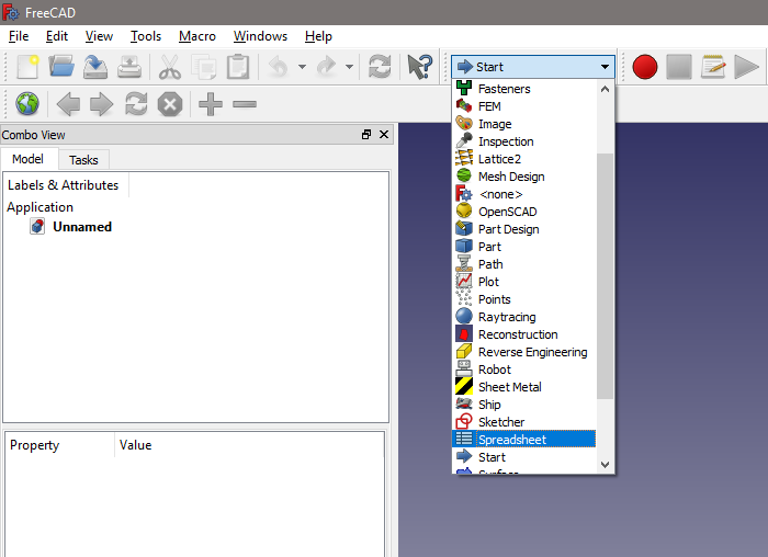
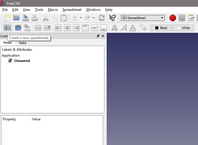
- Create a new document, then in Workbenches, choose Spreadsheet Workbench.
- Once the Spreadsheet Workbench opens, create a new spreadsheet by clicking the button.
Adding Parametric Spreadsheet - Step 3.
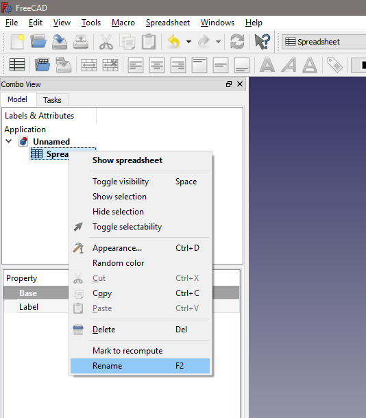
- I rename the spreadsheet to Dims, short for dimensions. You will be typing this into a lot of dialogs through this process, so you’ll want something short, and easy to remember. Do this by right clicking on the Spreadsheet in the Combo View.
Adding Parametric Spreadsheet - Steps 4&5.
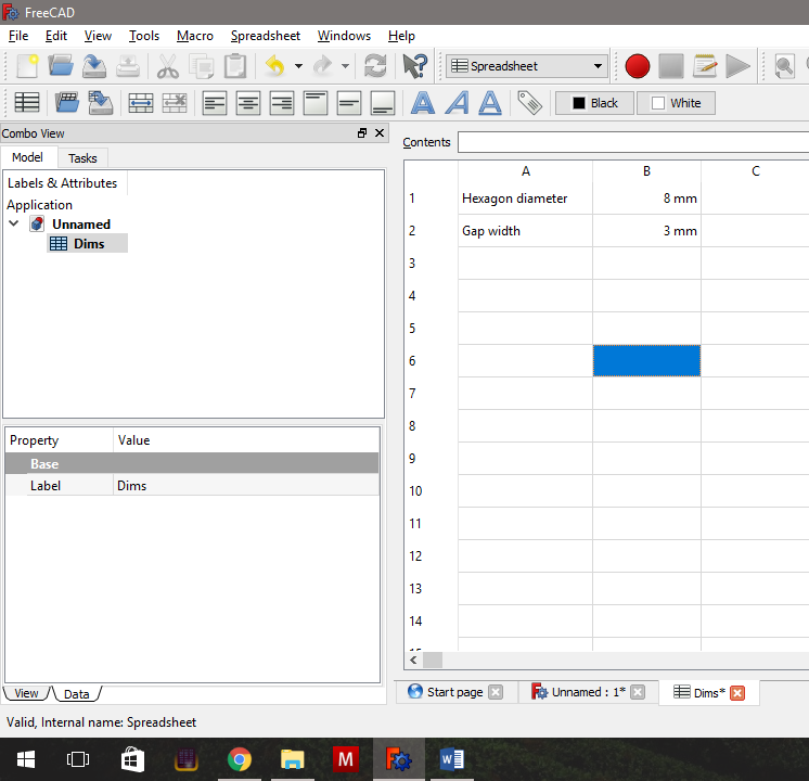
- Double click on the spreadsheet in the combo view to open it, and add the entries shown in the first of the pictures above. I’ve chosen a diameter of 8mm (the width from point to point) for the hexagons, and a gap between the hexagons of 3mm. Freecad is unit-aware, so unlike Excel, make sure to include your units in the cell. Before we close the spreadsheet, we have to assign aliases to the two cells with our measurements.
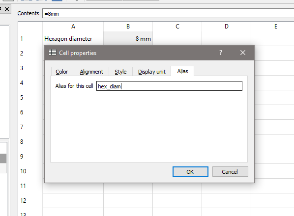
- Right click on the first cell (Note that the 8mm is greyed out in the image), choose Properties, and go to the last tab in the dialog window that pops up, the one called Alias. Again, you will want an easy to remember alias, that is quick to type. I chose hex_diam for the hexagon diameter, and gap for the gap width between the hexagons. Make sure to give the 3mm cell its alias as well.
Closing the Spreadsheet and Starting the First Sketch
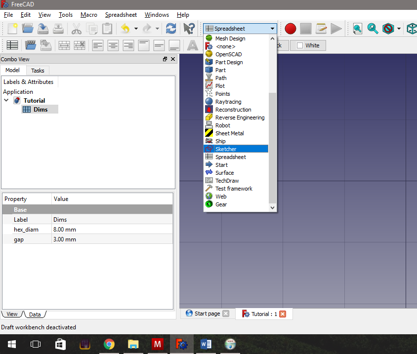
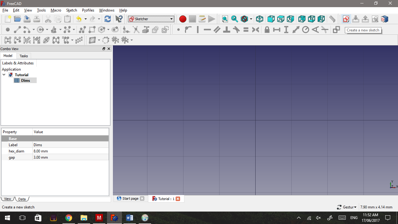
- Close the spreadsheet tab by clicking the little red cross on its tab at the bottom, and switch to Sketcher Workbench. This is also a good time to save the file.
We’re using the Sketcher Workbench because we want to use it to create two separate hexagons in a sketch, and then extrude them into two separate but linked shapes.
It used to be in Part Design, that a sketch containing two or more separate components would give you the same number of solid objects when extruded, but this was a behaviour that was never intended. Since 0.17, extruding a multi-part Part Design sketch will now only give you one solid.
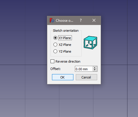
- Once the Sketcher Workbench opens up, add a new sketch on the xy axis. Note that I’ve shifted my toolbars around, so the button I’m selecting (the red circle and rectangle) may be in a different location for you.
Adding the First Hexagon and Copying It.
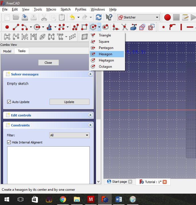
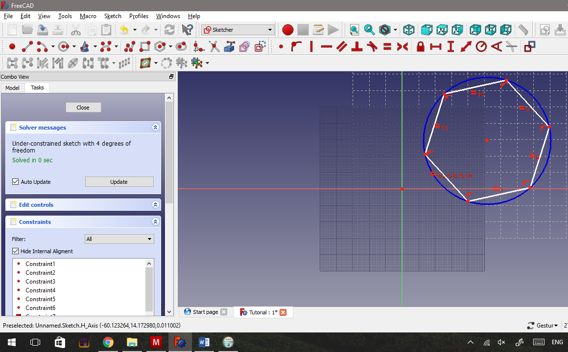
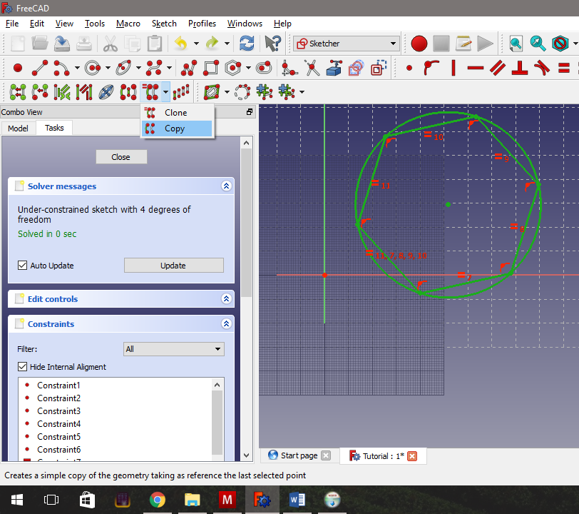
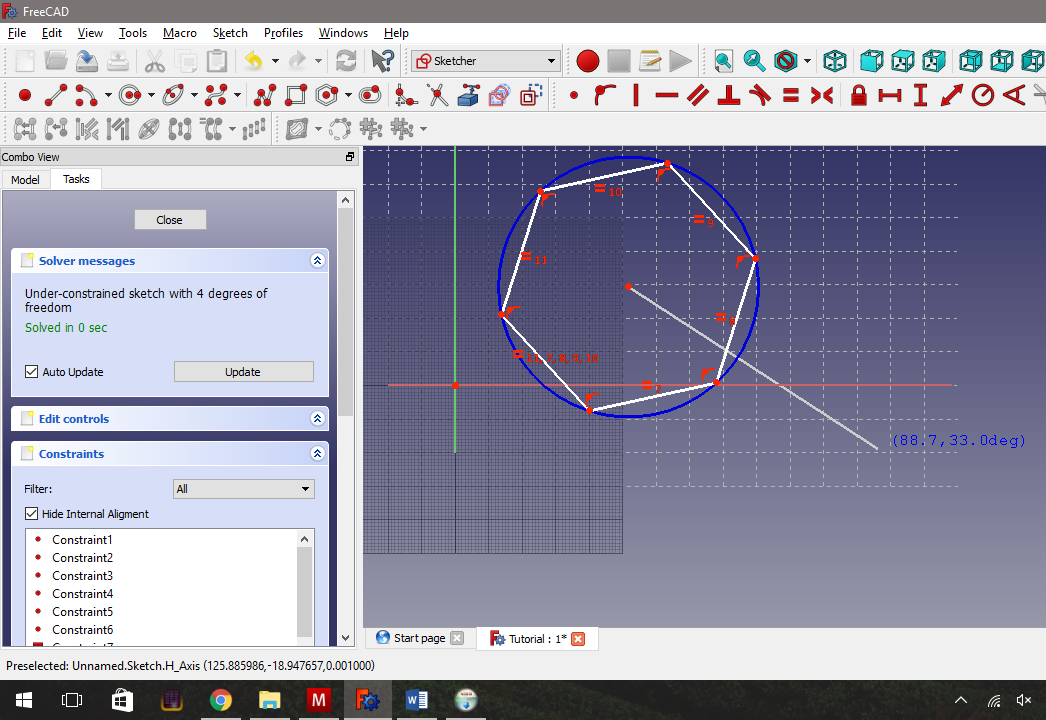
In the sketch view, you have three main toolbars, one containing all your sketch tools (To the left in the second row in my setup), one containing all your constraint tools (To the right in the second row) and finally one containing your copy tools (to the left on the bottom row). There are other toolbars, but these are the important three.
In Freecad sketches, the workflow is like this:
- You draw your geometry loosely; and
- Then use constraints to force that geometry into its final form.
You have to be careful not to over-constrain the geometry, because Freecad will throw an error message if you do, and refuse to update the geometry.
- Choose the Regular Polygon tool from the sketch tools, and use it to draw a hexagon in the sketch. Don’t worry about its size or arrangement, because as stated above, we will use constraints to jam it into place.
-
Use your mouse to select the entire hexagon, including the blue construction circle. All of the geometry should turn light green.
-
Now choose the Copy Geometry tool from the copy tools, A new line shows up in the sketch, which represents in what direction and how far the copy will be placed away from the original copy. Place the copy to the right and below the original hexagon.
I wanted to show you the Clone tool rather than the copy tool, as this would create a copy that is dynamically linked to the original geometry. If you rotate or resize the first hexagon, the second one changes immediately. Unfortunately it seems this tool's behaviour is still unreliable in the development 0.17 version of Freecad.
Adding in Our Constraints - 1st Horizontal Constraints.
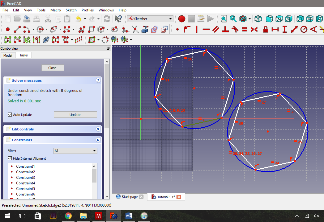
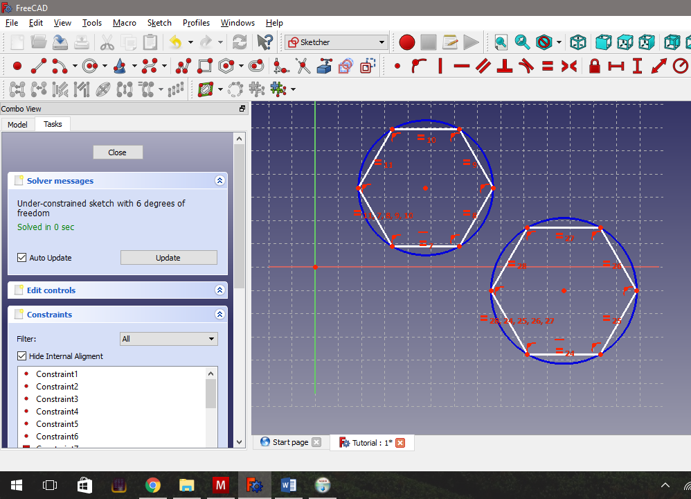
Now it’s time to add the constraints. I will state that sometimes using the Freecad geometry tools can be incredibly frustrating. Each tool has a certain number of geometric objects of a particular type, that it will ONLY work on. If you accidentally click the wrong object, Freecad will complain and either do nothing, or do the wrong thing. In either case you will have to start again. I much prefer to select the geometry FIRST, and then click the constraint tool.
With that in mind, we want to add the following four constraints:
- We want the bottom of the hexagons to be horizontal.
- We want both hexagons to be the same size.
- We want the diameter across the hexagon to match what we placed in the Dims spreadsheet. This will require some calculation as this constraint is easier to add as a radius constraint, and not a diameter constraint.
- And we want the gap between the hexagons to match what’s in the Dims spreadsheet, and this to be measured at right angles to the hexagon edges. For this last constraint, we will need to add some construction geometry.
- First, for the horizontal constraint, select one edge of one of the hexagons and click on the horizontal constraint button (It’s the one that is a single horizontal line.) Do the same thing to the other hexagon.
Adding the Second Constraint - Equal Size.
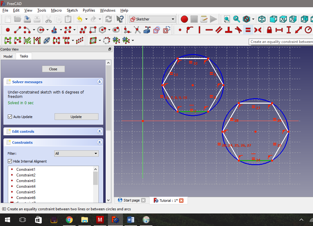
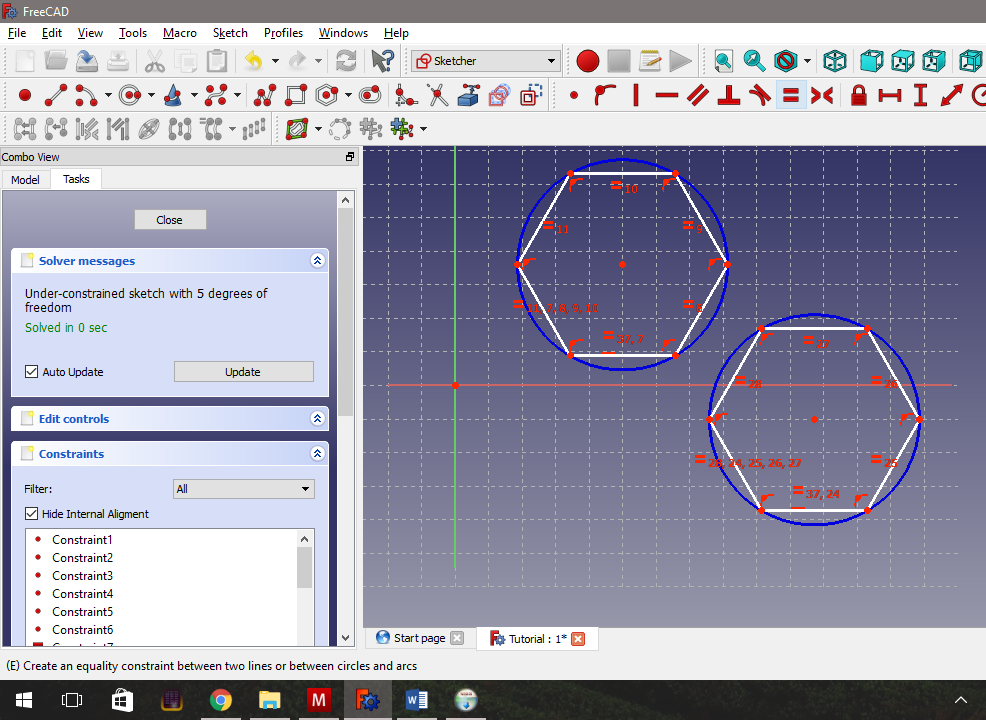
- Now select one line from each hexagon and click on the equality constraint (The one that looks like an equals line).
The equality constraint is the most flexible. You can choose several lines (more than two) and make them all the same length, or several circles and make them the same diameter.
We only chose two lines here because if you look to the list of constraints to the bottom left, you will realise that Freecad adds a lot of constraints automatically, including the ones that make each hexagon a regular hexagon.
Adding the Third Constraint - Setting the Hexagon Diameter
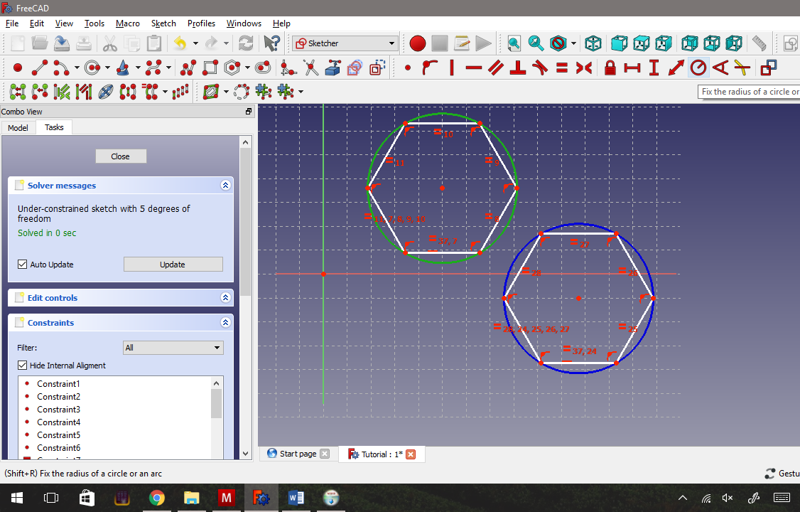
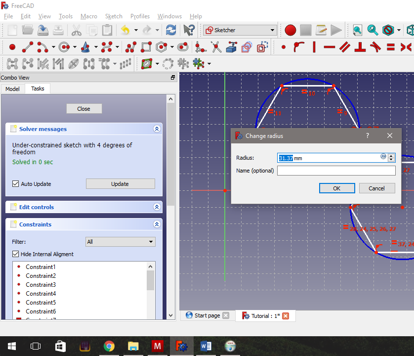
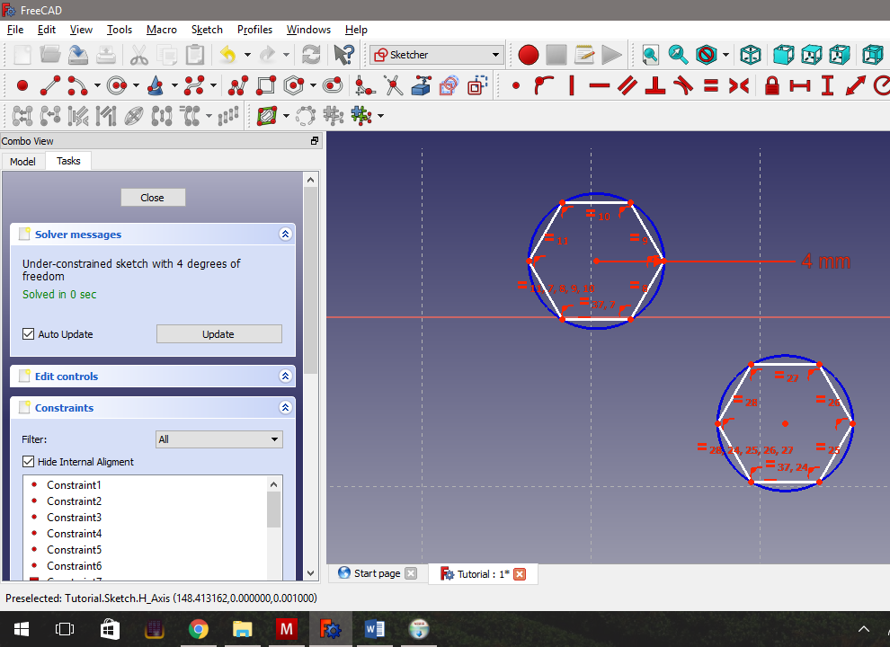
- Now for the third constraint, choose one of the blue circles and click the radius constraint tool. This will pop up a dialog where normally you could type in what radius you want. We will be doing something a little bit different.
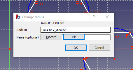
- Beside the box for the distance, you will see a little blue circle with the letters fx in it. Clicking this circle brings up Freecad’s formula tool. Note the formula I have typed into the box: Dims.hex_diam/2. This will go to the Dims spreadsheet, look for the cell that has the alias hex_diam, and then divide it by 2.
- Press OK in the formula tool, then press OK in the constraint dialog.
- Doing this, I found the two hexagons immediately shrunk (because they both shared a line equality constraint) so that I had difficulty seeing them. I selected one of the dots on the first hexagon, and used this to drag it closer to the second hexagon, before zooming in to the final picture above.
Adding the Fourth Constraint - Setting the Gap Width
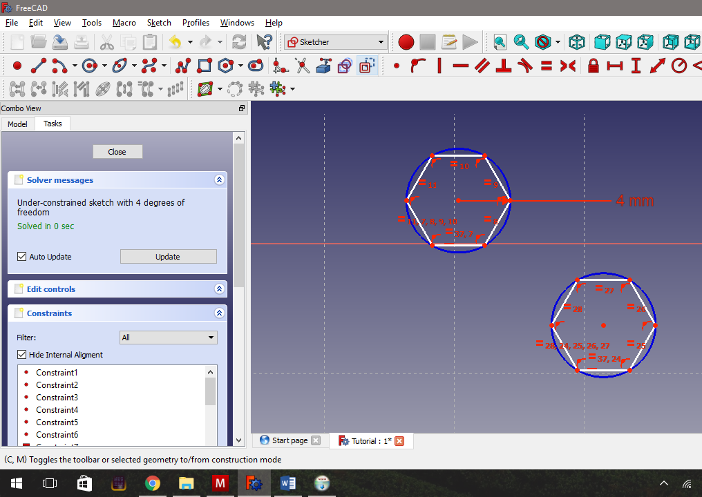
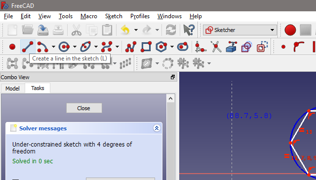
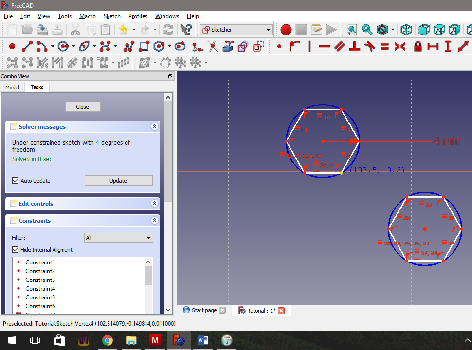
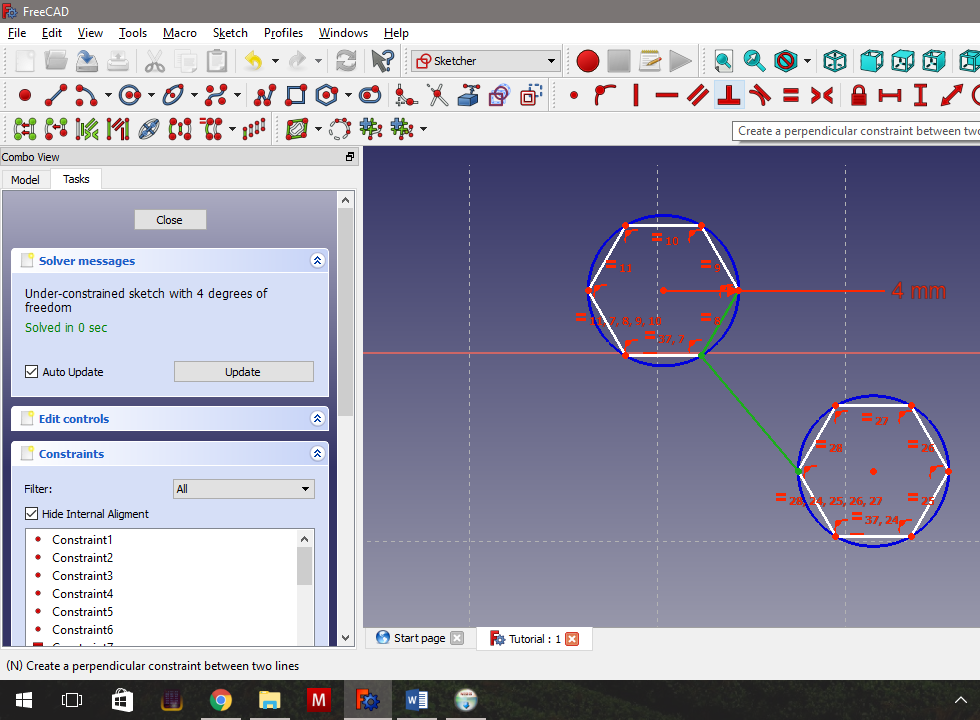
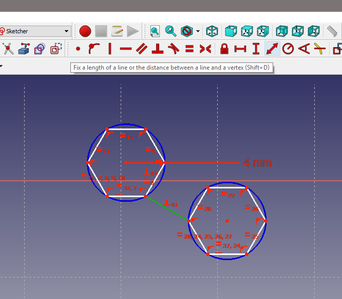
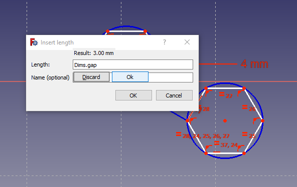
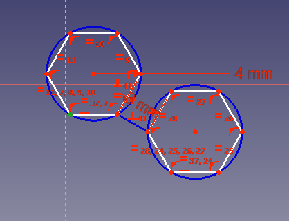
The final constraint we want to add, is the gap constraint. But we want to measure this straight across between the two hexagons, not at an angle. None of our constraint tools will do this by themselves. We need to add a little construction geometry to help things along.
- Click the Toggle Construction Mode button (the white and blue squares) to switch to construction mode. You will note that all our sketch tools turned blue.
- Use the line tool to draw a line between the two hexagons. Be especially careful to ensure that the line is drawn from point to point. (You will notice that the cursor pops up a little dot when you get near the point, and the point changes colour.) This is the fiddly bit. You HAVE to get this right. If you don’t, CTRL-Z and try again.
- Now we want to force the line to be perpendicular (right angles) to both hexagons. Select the construction line, and one line on a hexagon, and then select the perpendicular constraint tool (the one that looks like an upside-down T).
- Now, select the construction line and chose the distance constraint tool (This one looks like a double headed arrow).
- In the dialog that pops up, click on the little blue circle again, and add the following formula: Dims.gap and press OK for the formula editor, then OK for the dialog.
Zeroing the First Sketch and Closing.
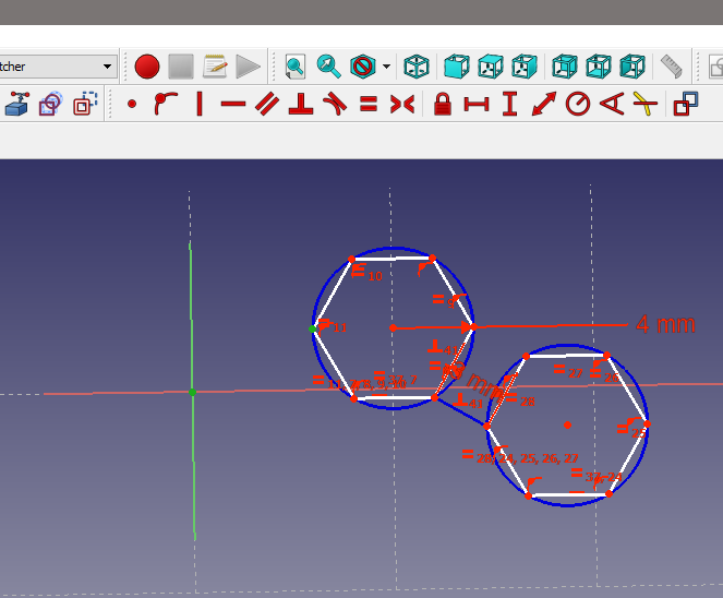
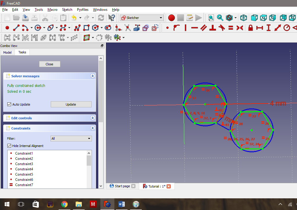
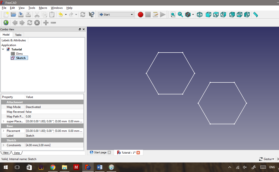
- Finally, select one of the dots to the left of the first hexagon,
- zoom out and select the single dot that is sitting by itself on a horizontal and a vertical line (this is the origin 0,0 of the sketch, and the two lines are the x and y axes.)
- and click on the Coincident Constraint tool (The one that looks like a red dot, beside the dot on the circular arc.)
The entire sketch will turn green (except for the construction lines). This is Freecad’s way of telling you that the sketch is entirely constrained. The reason for doing this, is that Freecad will place the solid geometry in relation to the sketch. If we have the sketch built on the origin (0,0) it makes it easier for us to predict where the solid shape will be if we move things around.
- Close the sketch by clicking the Close button in the Combo view, then press the following keys in the geometry view V F to make the screen fit what we’ve just created.
Creating Geometry to Measure - Second Sketch
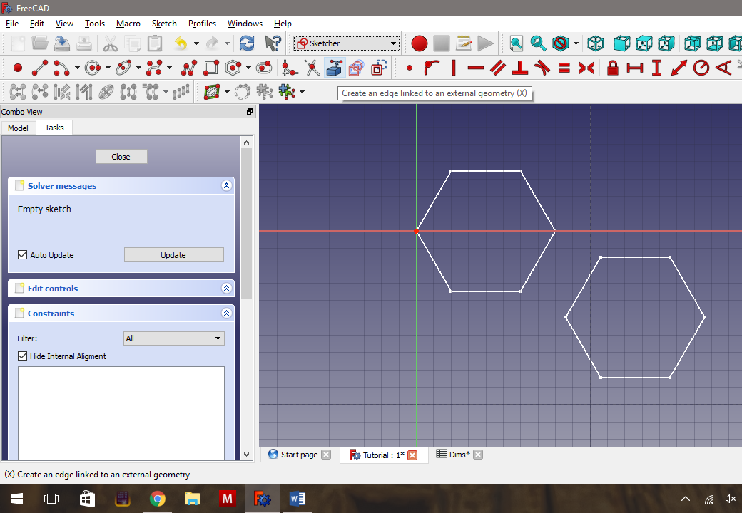
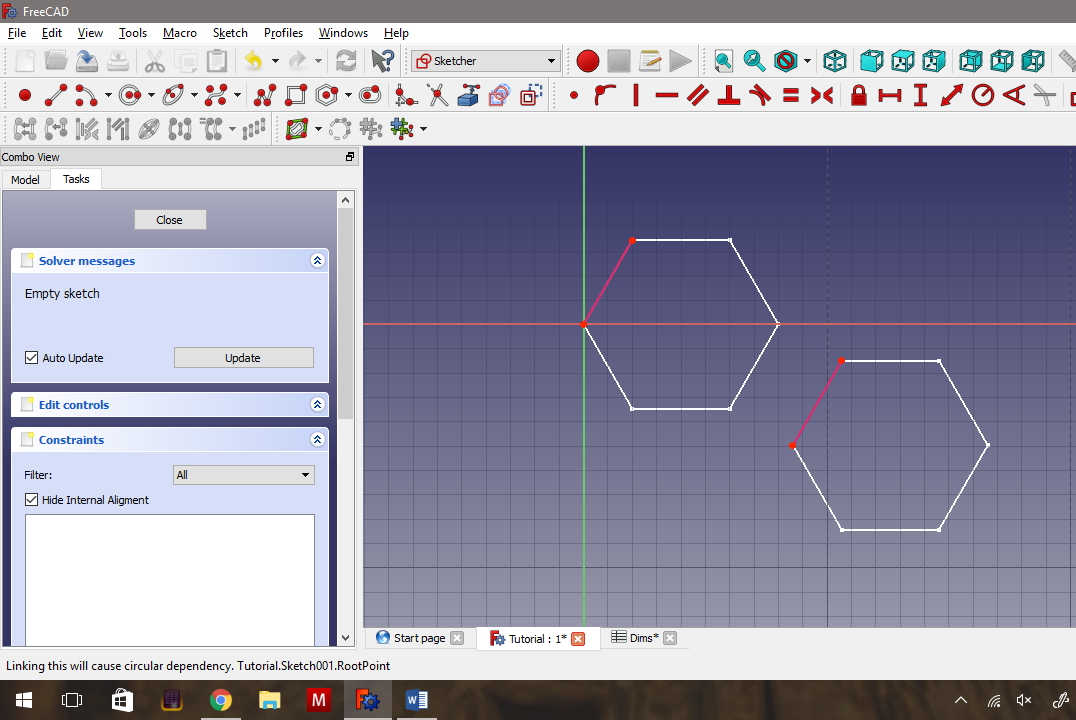
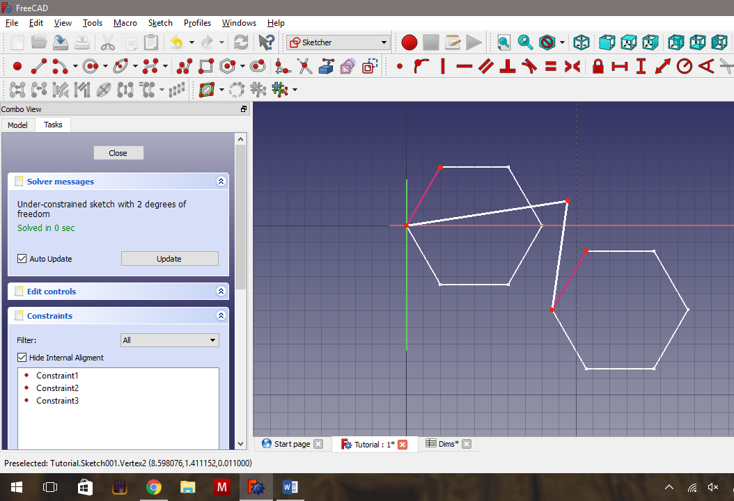
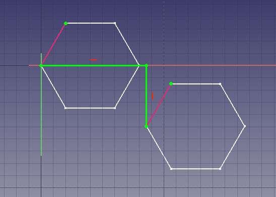
Now comes the fiddly part. We want to measure how much the second hexagon has been offset from the first hexagon. Unfortunately, Freecad doesn’t have a method for doing this neatly yet, at least in a way that will allow the measurements to update if we shift things around. We’re going to have to hack together a couple of things in order for this to work the way we want it to.
- First, we need to create another sketch on the xy plane.
- Once the new sketch is open, click the External Geometry tool, and click one line from each hexagon.
- Create a line from a point on the first hexagon, out to the right. (It’s actually better to ensure the line isn’t horizontal.)
- Then add a line from the end of the first line, down to the matching point on the second hexagon. Refer to the pictures to ensure this step is clear.
- Select the horizontal line, and add a horizontal constraint, then select the vertical line and add a vertical constraint.
Making the Measurements Using Draft Dimensions
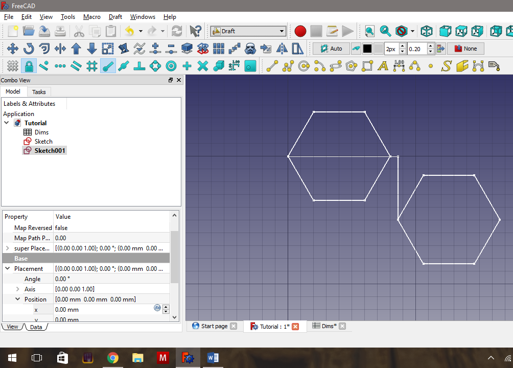
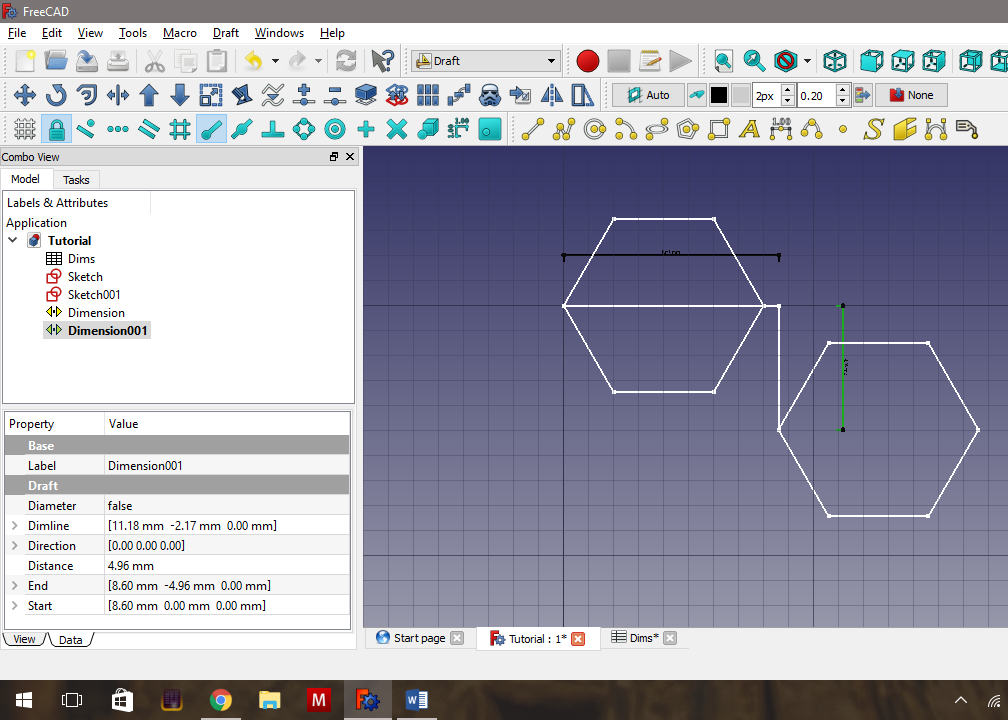
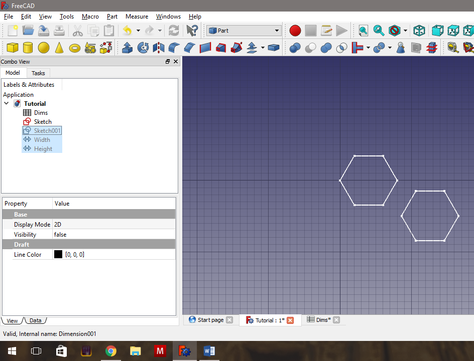
- Exit the second sketch, and switch to the Draft Workbench.
Now, click on the button for the Dimension tool (The yellow button with the number 1.00 across the top).
Hold down the ALT key, and click on the horizontal line of the new sketch. Then move the mouse up vertically, and click once. This creates a dimension line that is pinned to the length of the horizontal line in our second sketch.
Repeat the step above for the vertical line, moving the mouse to the right.
I rename the horizontal measurement Width, and the vertical measurement Height. By using the ALT key, and selecting a sketch edge, if the edge changes length, the Dimension changes to match it.
We only want the measurements, not the actual objects, so our next step is to make the Dimension lines and the second sketch invisible. In the Combo view, select all three of these and press SPACE.
Extrude the Hexagons
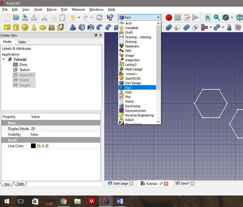
- The next step is to switch to Part Workbench,
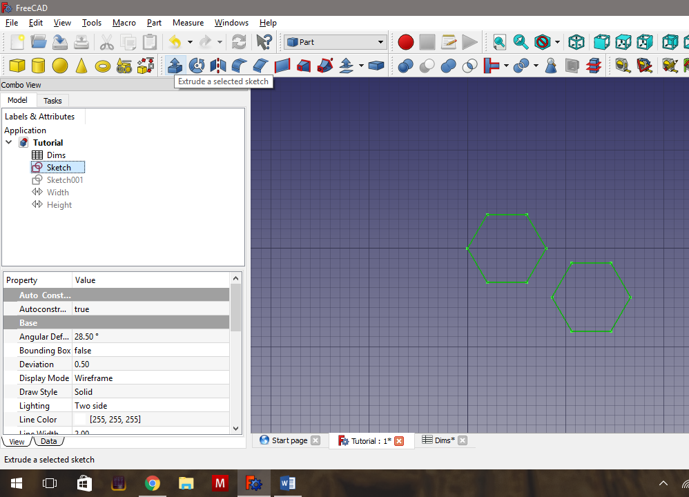
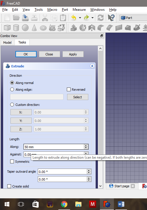
- Select the first sketch and click the Extrude Tool,
- Change the Length -> Along value to something large like 50mm,
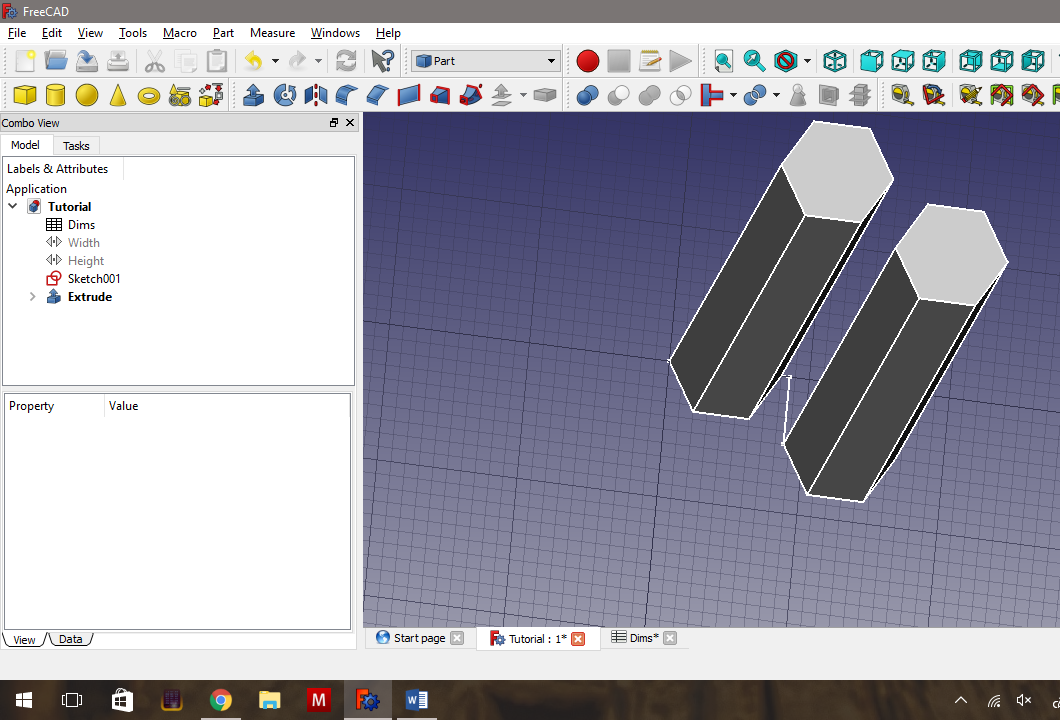
- and press OK. This will result in two rectangular prisms 50mm long. (I’ve rotated the view in the last image, to make the geometry more apparent.)
Create the Array.
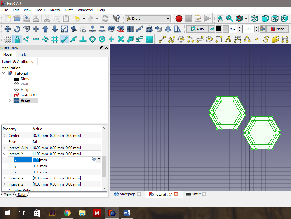
Now we’re ready to create an Array from the prisms.
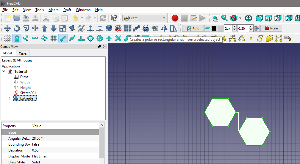
- To do so, we need to go back to the Draft Workbench, select our new prisms, and select the Array Tool (The blue one that looks like a rectangle of 6 cubes).
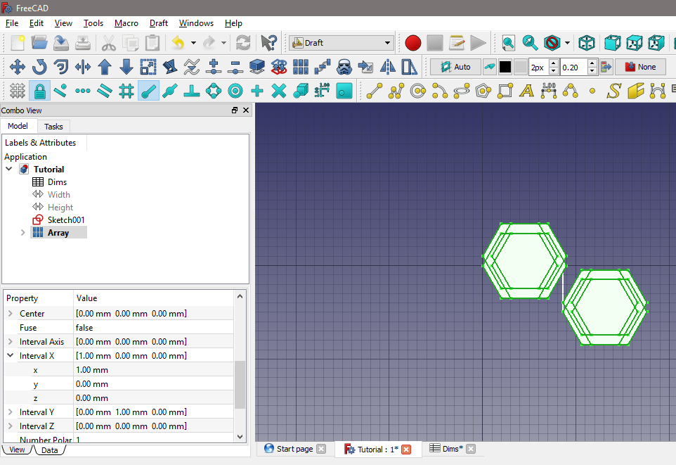
This doesn’t produce a dialog, but creates the Array immediately, with default values. We will want to change these in order to create the array we actually want.
- Go to the Data tab in the Combo View, and scroll down until you get to Interval X and Interval Y.
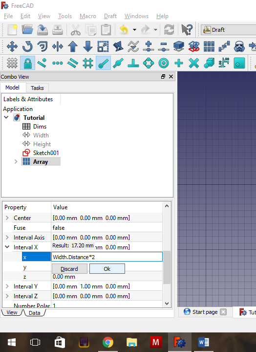
- We want to edit the x value of Interval X. Click on this entry and then click on the little blue circle that pops up to enter the Formula Editor again.
- The formula we want to add is: Width.Distance * 2
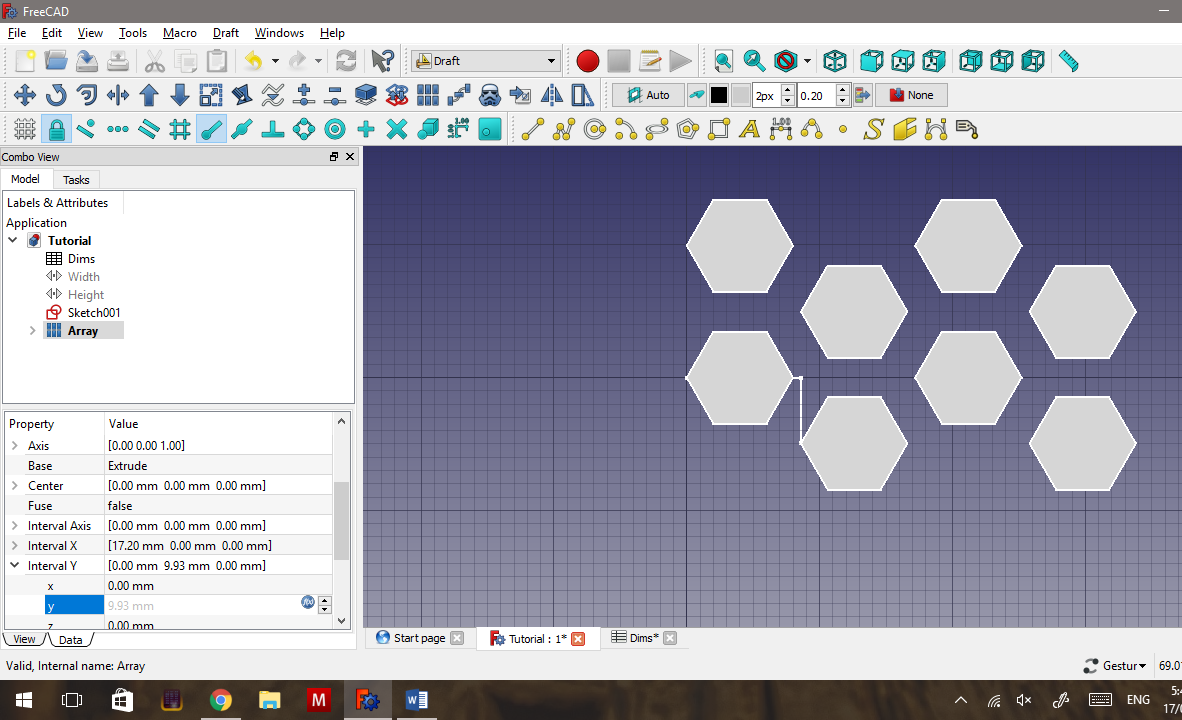
- Press OK, then press Enter to cause the horizontal copies to shift two widths to the right.
- Then change the y value of Interval Y to Height.Distance*2, press OK, then press Enter to cause the vertical copies to shift two heights up.
Resize the Array.
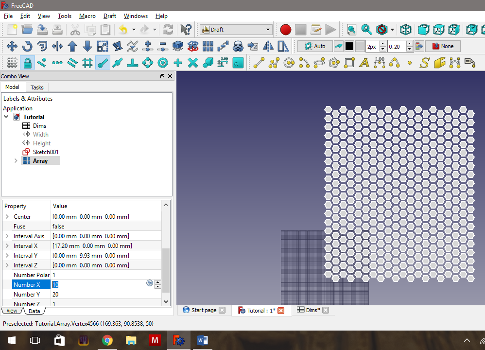
- To create more hexagons, we go to Number X and Number Y in the Data tab of the Combo View. I created 10 horizontal copies and 20 vertical copies. The numbers don't matter, you just want the Array big enough to cover what you want to chop them out of.
Create Geometry in Order to Mesh.
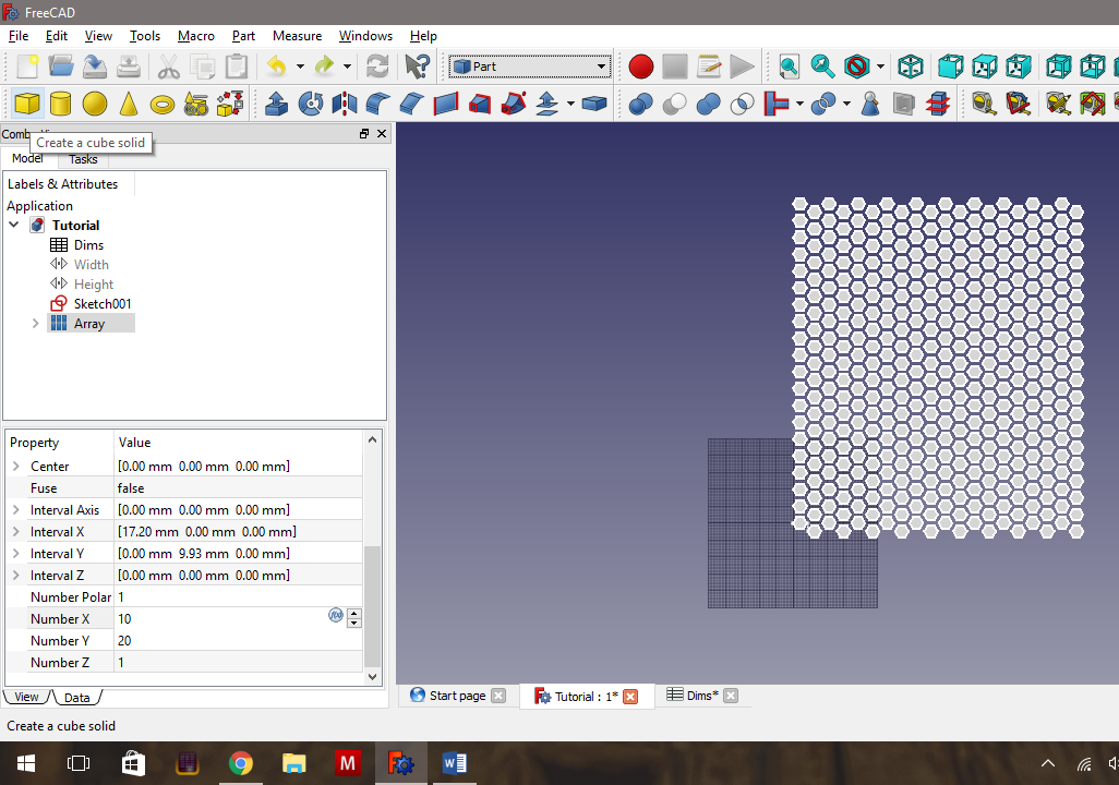
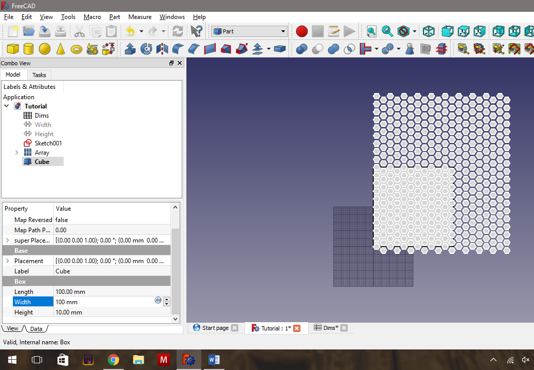
The final stages are to create an object (In this case, a thin rectangle), and chop the hexagons out of the object.
- We need to go to the Part Workbench, and create a Cube (The yellow cube button to the left).
- Select the Cube in the Combo View, and in the Data Tab, and change the Length to 100mm and the Width to 100mm. Leave the Height at 10mm.
Ensure the Hexagon Array Fully Covers the Object to Be Cut.
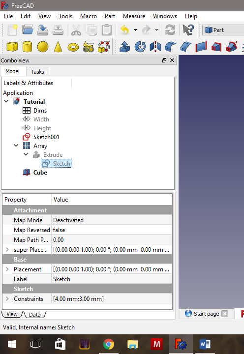
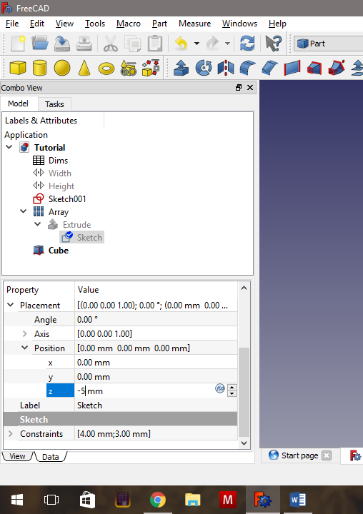
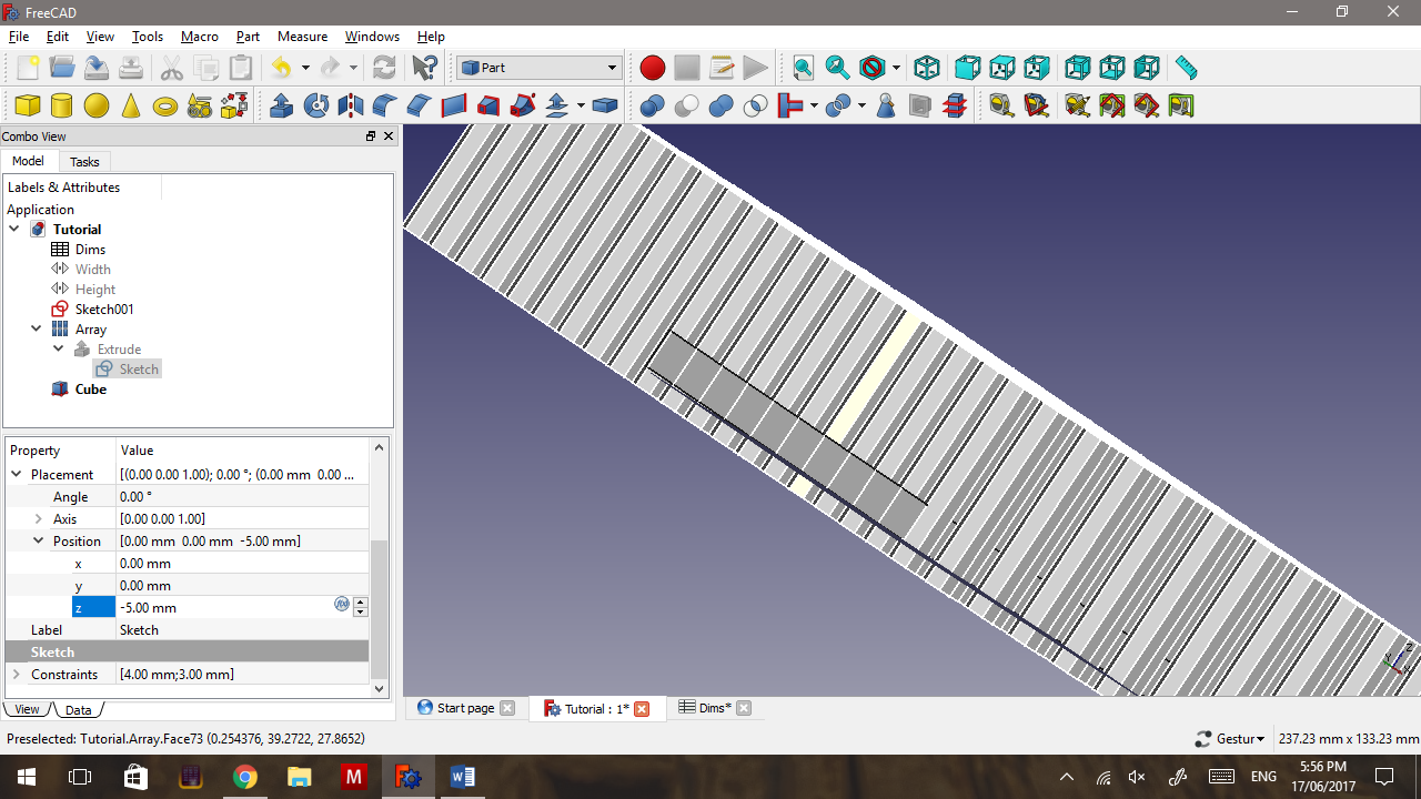
We want to ensure that the Array cuts entirely through the rectangle (Cube).
- We do this by selecting the arrow to the left of the Array, the arrow to the left of the now-visible Extrude and then select the Sketch.
- In the Data tab, go to Placement > Position > z and change it to -5mm.
Some important points regarding 0.17. Most objects have a Position and a Superposition option. Usually only one works in a given situation, and its usually trial and error for which one you should use. Also, when an object is derived from another (Like Array depends on Extrude, which depends on Sketch), the only way currently to change the Array’s position, is to change the bottom-most object’s position.
Superposition is the first attempt at making this more flexible. In the future, Superposition will enable the user to move any object relative to the objects it is formed from, while Position, as it currently exists, will vanish completely. Currently we’re in a situation where neither system is really complete so as mentioned, it’s usually a case of trial-and-error.
Boolean Cut
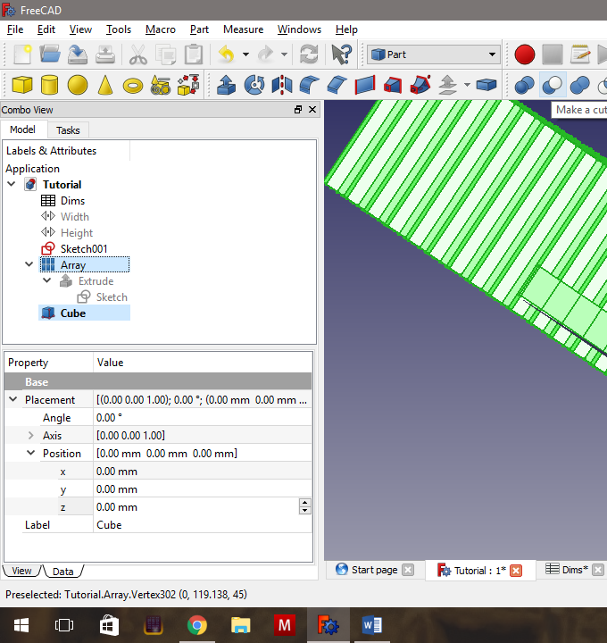
So, now we have a hexagonal Array that cuts through our rectangular plate.
- Select the plate (called Cube in this example), hold down CTRL and select the Array (but not Extrude or Sketch), and then click on the Cut Boolean Tool. (The blue and white sphere, where the white sphere cuts into the blue sphere).
This will take some time. Also, Freecad’s Boolean tools aren’t always that smart and may require you to jiggle objects around by a few thousandths of a mm. This time I got lucky.
Final Product - a Hexagonal Array That Is Easy to Edit.

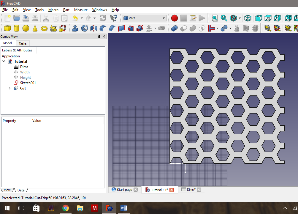
And we're done. Now if we want to change the size of the hexagonal holes, or the thickness of the walls between them, we only have to change the appropriate cells in the Dims Spreadsheet. Note that it does take some time for Freecad to recalculate everything when you change one of these settings.
In the second picture, I have changed the hexagonal diameter to 12mm, and the gap to 4mm.
You are also not restricted to cutting a rectangular sheet. Instead of using a cube, you can cut the hexagons into a circle, an extruded sketch, or even Bezier curves imported from an SVG file or an imported STL/OBJ mesh. Anything that you can turn into a solid, and Freecad can cut with a Boolean operation.
To print the mesh, just select the final Cut object, then go to File->Export and choose what format you want to save it as.