Adrianino. ATtiny 1614. UPDI.
by AdriánT30 in Circuits > Microcontrollers
5748 Views, 13 Favorites, 0 Comments
Adrianino. ATtiny 1614. UPDI.

The following project was born with the idea that electronics is very easy to learn and modular at the same time. Although I have already finished my Fab Academy, I am still researching. Speaking with my instructors Nuria and Pablo, I told them that I wanted to continue working on the Hello World project, but I was not satisfied with making a board for each sensor or actuator.
So I decided to make a board with the ATtiny1614, where I could use the maximum pins for the inputs or outputs; that had external power; I2C connection. The idea is that a student can test as many sensors as possible, become familiar with electronics and programming little by little. And the Adrianino was born. Furthermore, I wanted to go one step further and place a VCC pin next to the UPDI programming pins, which I will explain later on how it works. This version of Adrianino has been updated for the new Serial-UPDI converter.
Features

- This board has FTDI and UPDI + VCC connection to program it without the need for external power (or the FTDI).
- It contains a voltage regulator to power the board with a power supply (9V battery).
- It has another 9V power connection to for example power a DC motor driver.
- Then there are 4 outputs or inputs with VCC and GND on each side to be able to connect different inputs or outputs.
- On the left there is an I2C connection to connect an LCD, OLED or a sensor that uses this communication.
- There are 3 outputs or inputs at the bottom and with a GND pinout.
- There is an LED and an integrated button, which will help us to test that the microcontroller works with a simple program.
- Through the FTDI connection we can read the data from the different sensors through the Serial.
Datasheet

ATTINY1614
As we have looked at the graph, there are more microcontrollers within the tinyAVR-1series family. Another ATtiny I use is the 1614. I combine the Datasheet image with the one from the SpenceKonde website on the ATtiny1614.
- 14 pin package.
- Two internal clocks 16 and 20 MHz.
- 16 KB Flash Memory.256 B EEPROM.2 KB SRAM.
- Maximum voltage: 6V; minimum voltage -0.5 V.
After looking at the basic features, you will find the pinning of the microcontroller.
BOM and Schematic for Adrianino


This is the schematic where you can see all the components. More information here.
Board Design


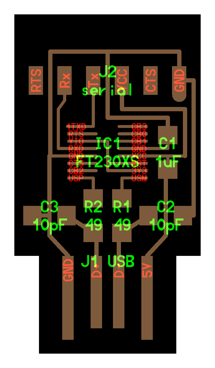
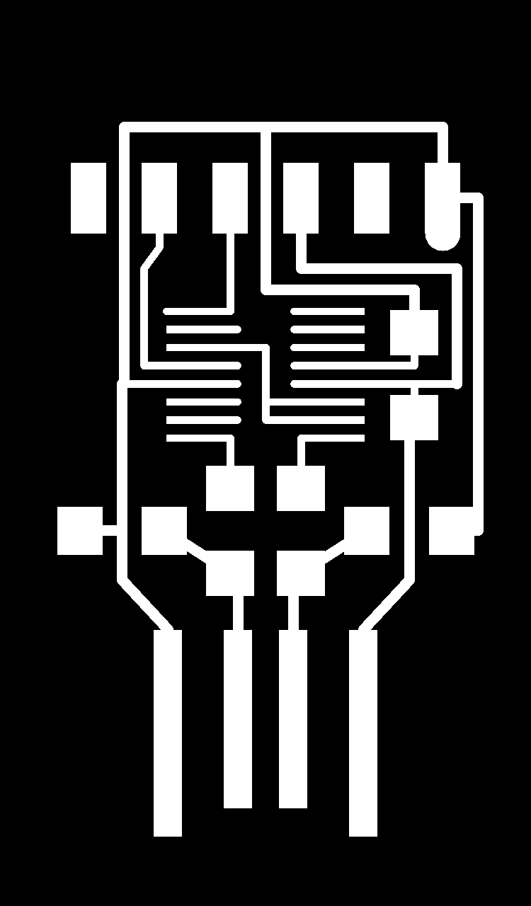
Here you can download the Eagle files and the PNG's. Here is a sample of the PNG's, traces and cutting lines. The files are for milling with a CNC machine.
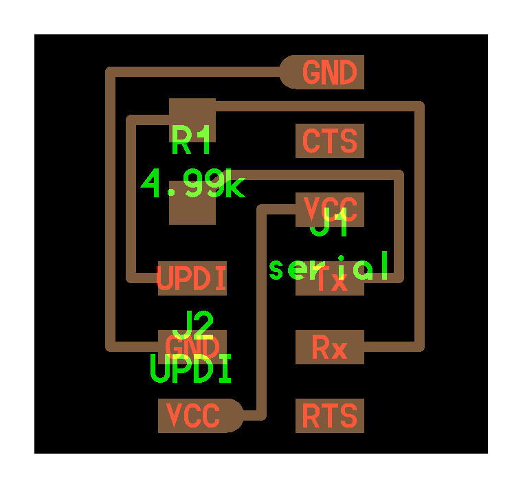
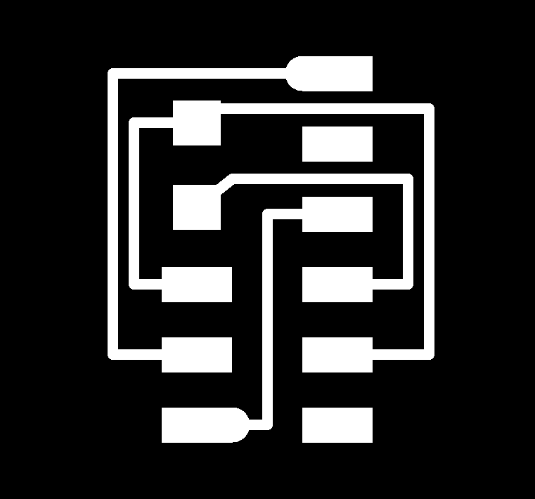
UPDI + VCC Module

You can find the files to create your Serial - UPDI + VCC converter here.
UPDI + VCC converter
Operation

The connection is very simple, we only need the FTDI-USB and we connect the UPDI + VCC module to the board, in this case to the Adrianino that has the three pins (UPDI + GND + VCC).
Programming With Arduino IDE and Windows.

Video Tutorial
Inputs and Outputs.

You can connect different sensors and actuators. In the following video you can see several examples. In this link you can find more documentation.