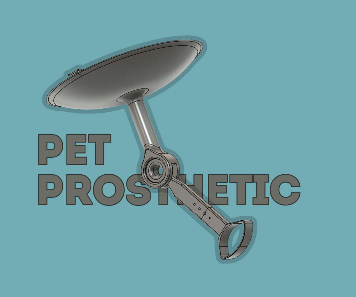
Adjustable Pet Prosthetic
.png)


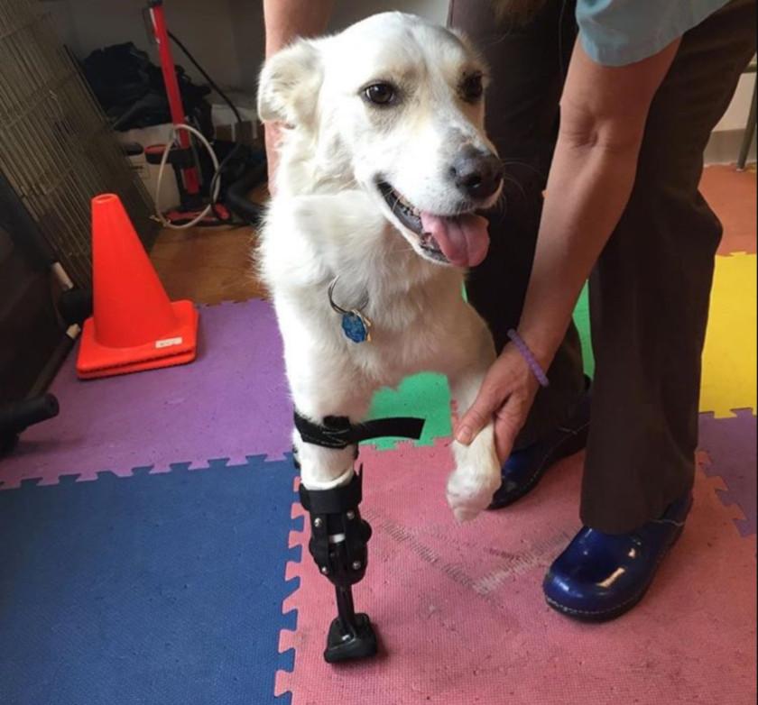
Greetings everyone! Welcome to my instruct able, where I will be showing you the process I used in order to create this Pet Prosthetic device that has able to carry necessary loads of most domestic canines and feline animals and has adjustability factors in both angle and length. Firstly, I want to detail a story that I recalled as I thought of the idea for this particular device. When I was 10 years old, I visited India for the second time, and, during my stay at my grandparents'' house, I looked out the window and recall seeing a 3 legged dog leaping from the walls of one compound to the walls of the next. Initially, I did not consider that this dog was missing a leg but merely that I might have been viewing it from a abnormal angle, but after looking at it prance around for a while, the reality dawned on me and my sympathy for the poor dog rocketed. I remember feeling helpless at this time and despite giving this dog some food with my grandparents, I could not help but think that this dog's life was jeopardy due to this development. When considering ideas about how I could help change the life of an animal, especially one of a pet that is near and dear to one's heart, I began to recall this experience and decided to bring a change through designing a prosthetic with more features than ones I have seen implemented on other animals. Let's change the lives of these animals one at a time with these prosthetic devices!
Supplies
- Fusion 360 Design Software
- Creality Ender 3D Printer
- PLA Filament
- Belts and Bands
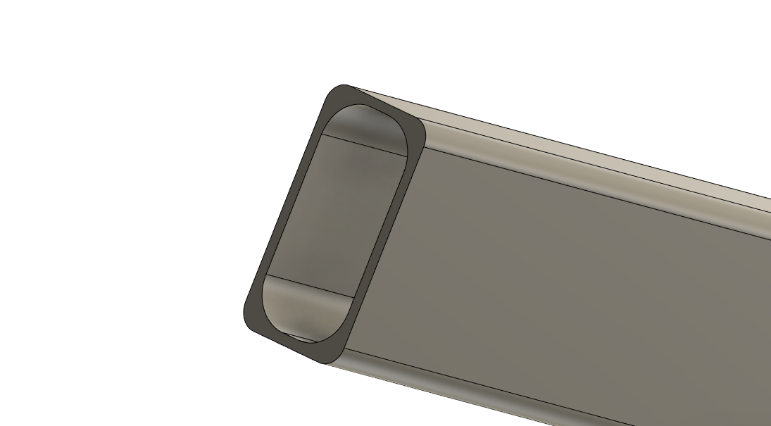
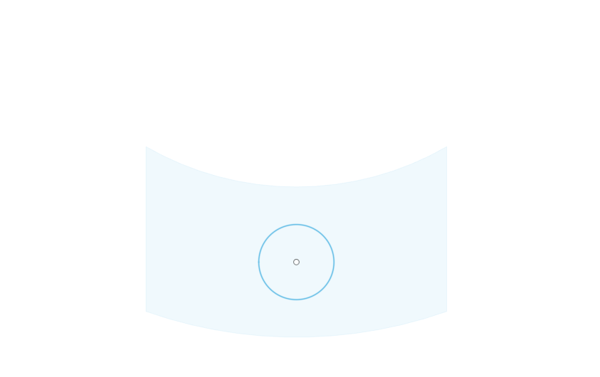
Create the Fitting Socket
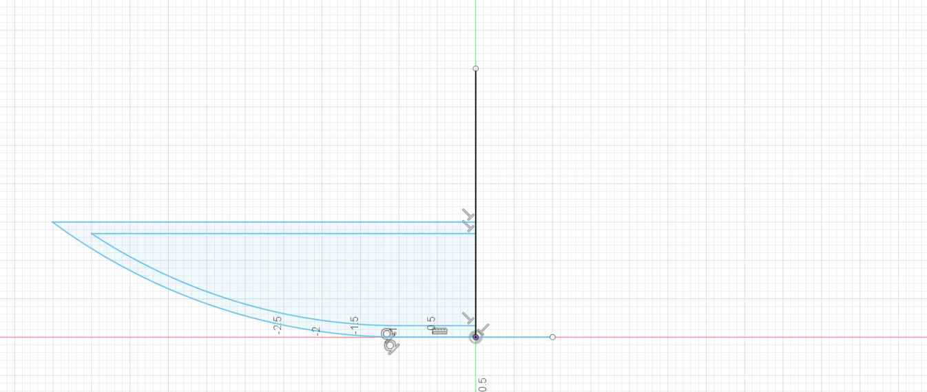
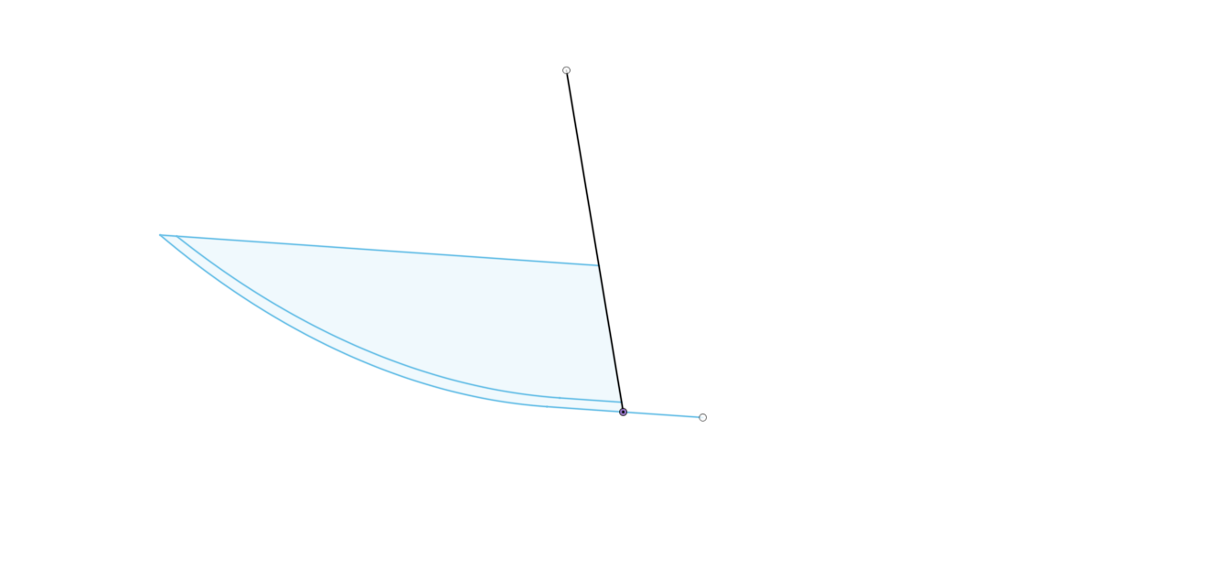
To start this process is fairly simple and most of you will be bale to complete this without concern or worry as it is merely just a 2 dimensional drawing created at the front view and rotated about a line stretching parallel to the Z-axis to create the cusp-like fitting socket for this particular mechanism.
- Open Fusion 360
- Go the front view and create a drawing
- Set this drawing to inches increment
- Create a vertical line as the axis of rotation at the origin
- Create a horizontal one-inch line perpendicular to the axis moving out
- Create an arc connecting the end point of the horizontal line and connect it upward to the desired point
- Create another layer, leaving a gap between the initial and second curve to add depth to the socket
- Complete the drawing and revolve the drawing amidst the axis
- If needed, add a finishing arc on the drawing before rotating in order to allow for some adjustability for the animal this will be used on
Creating First Socket & Joint
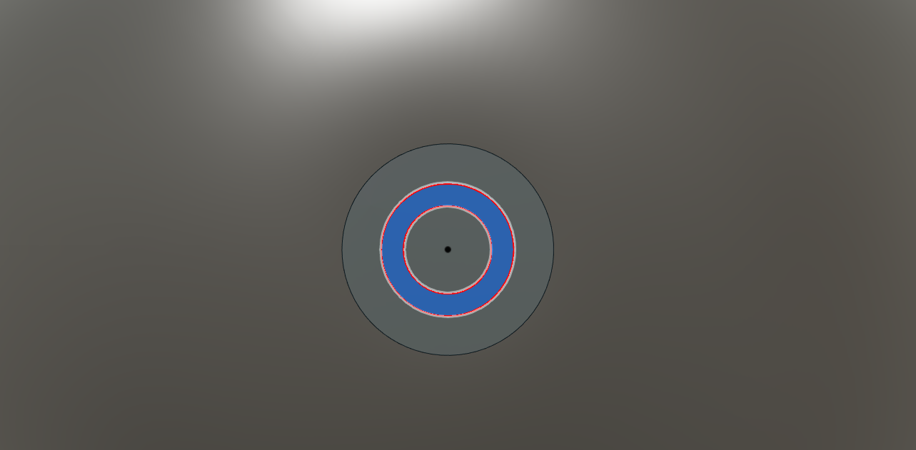
- Go to the bottom of the created socket and create a circle with the outside diameter being 1.6 and the inside diameter being 1.2 inches, respectively.
- Extend and extrude this circular region outward between 5-6 inches
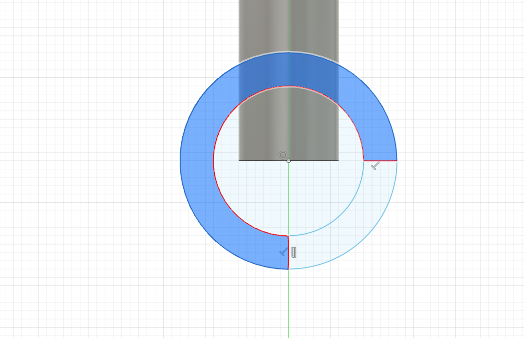
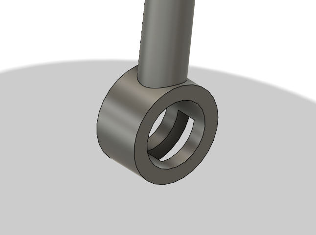
- Create another view on the right access and create a circle for the joint. Size does not strictly matter, bit choose one with a diameter noticeably larger than the outer diameter of the other circle.
- Leave the bottom right quarter of the circle exposed to create the gap in which rotation will occur for the adjustable angle factor.
- Extrude both portions outward to over the whole 1.6 inch diameter of the previous circle and more and then, using the same drawing, remove some central space in that bottom corner
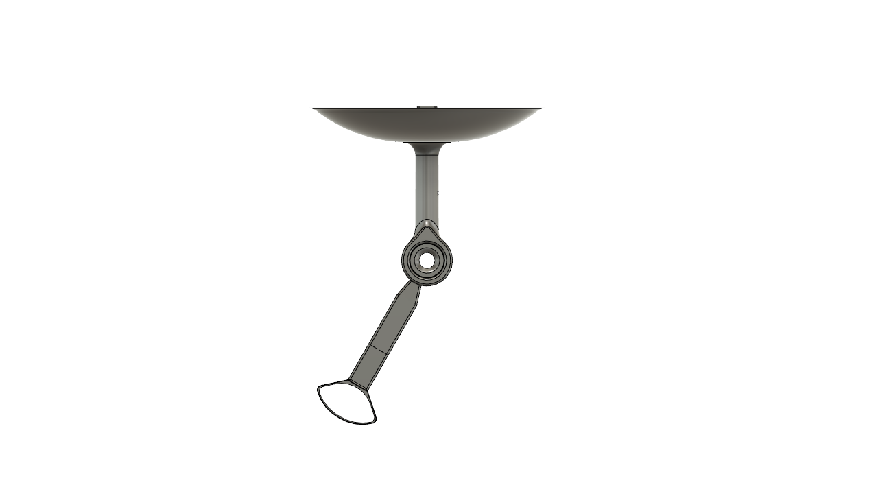
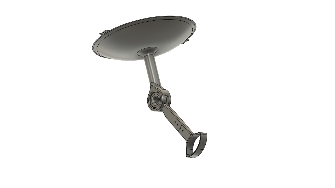
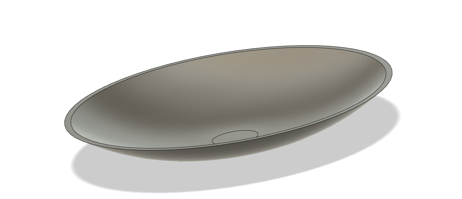
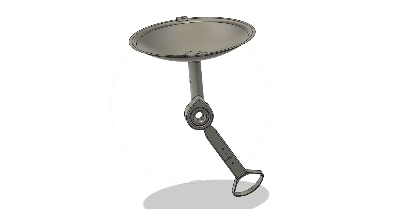
At his point, you should have your socket created, your first cylindrical support, and the joint around which the pylon second support will be able to move.
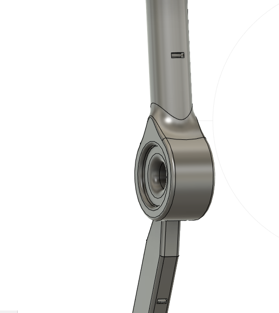
Creating Second Support (Pylon) & Shell
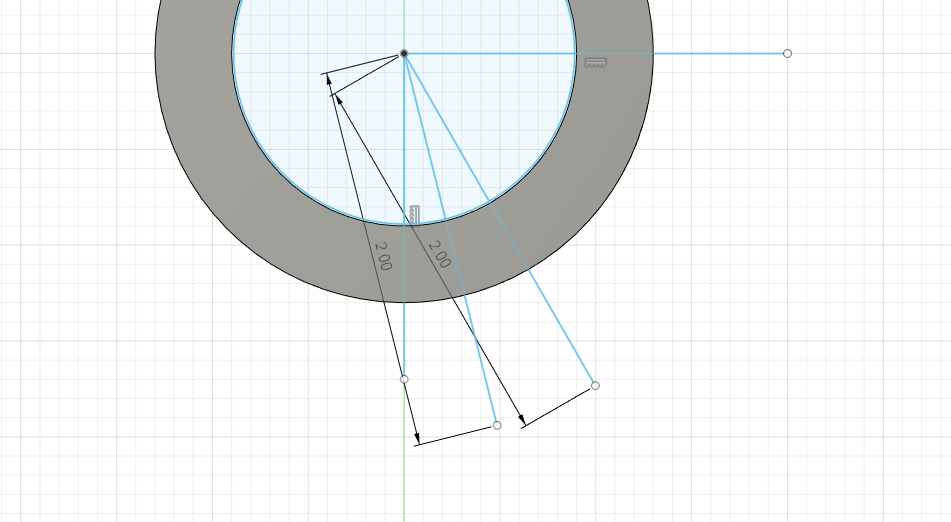
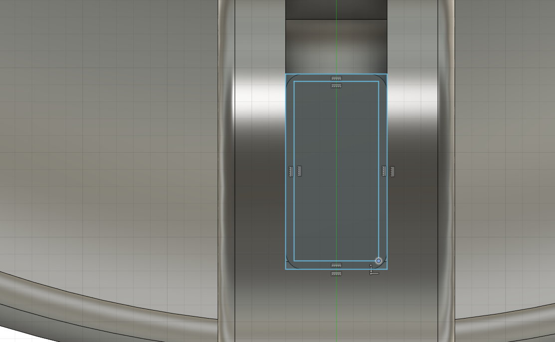
- Create a circle embedded within the circular space that is left within the joint previously created.
- Using the end lines of the quarter as guides, create an approximately 2.5 inch extension for the lines starting from the center to create the rotational piece for this particular joint.
- Ensure they are properly spaced out and provide them with a thickness within the limited space provided to them through extrusion
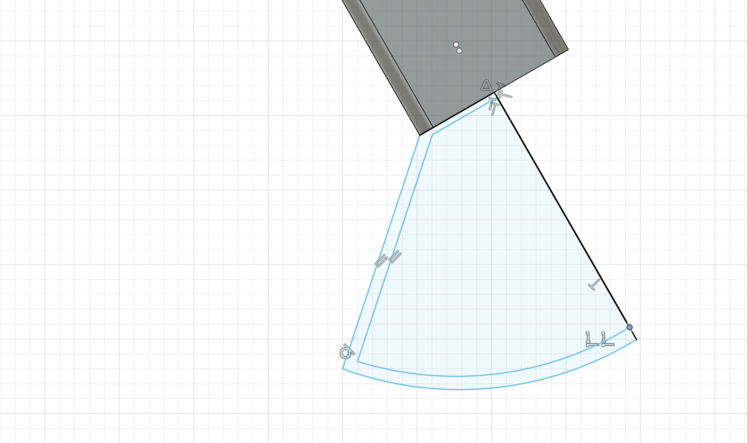
- Create a drawing on the angled face of the plane of the piece that just gained thickness and create a rectangle with small depth added for extrusion next.
- Extrude this piece around 5 inches as well, but this matters less as technically this part will be adjustable using the socket-button method that can allow for this to be used on a myriad of animals.
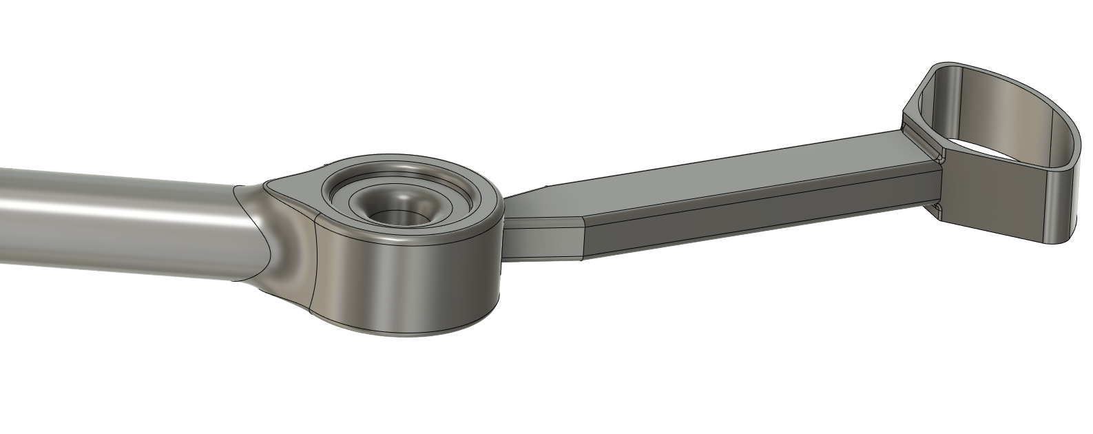
- Following extrusion, add some fillet on the edges of the piece and fillet other portions of the design as well in order to reduce the actual material amount and create a more seamless and integrated look.
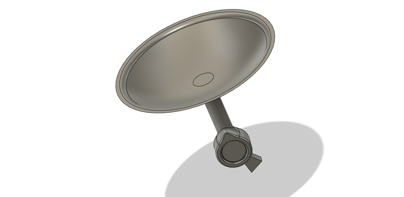
- Draw out the shell for the actual prophetic foot replacement and mirror it to the other side before extruding and filleting it
Adding Adjustability Factor + Final Modifications
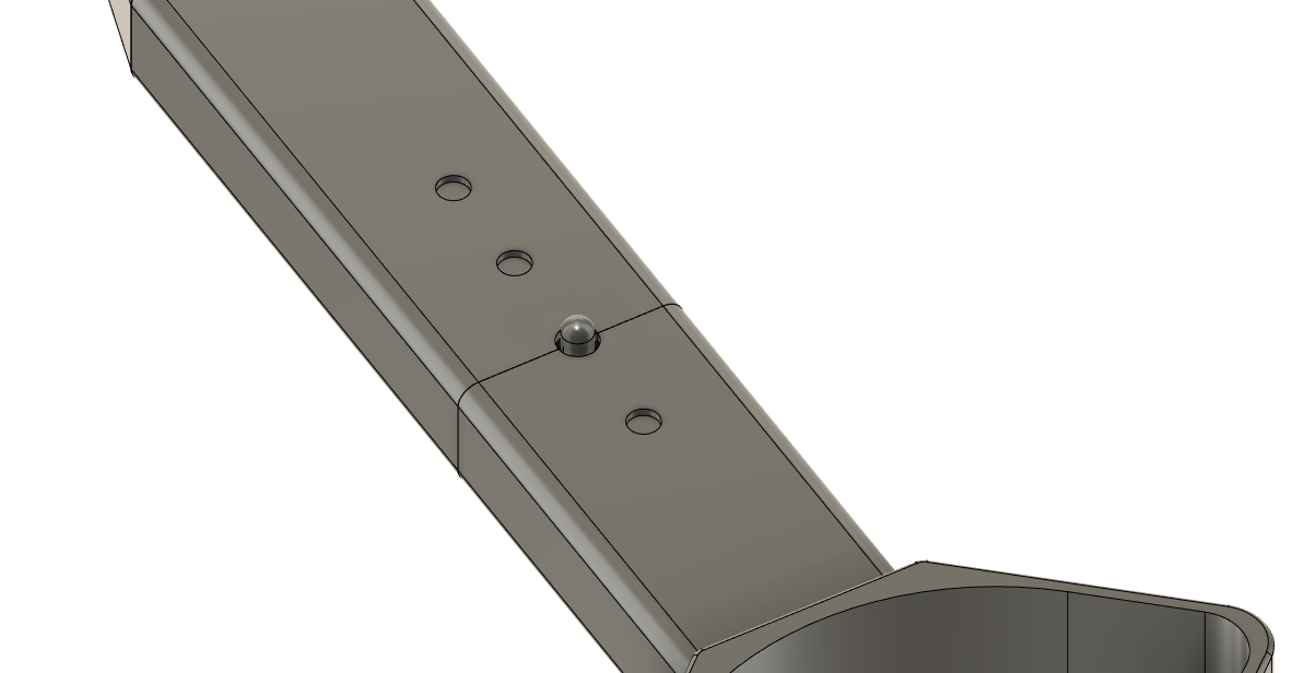
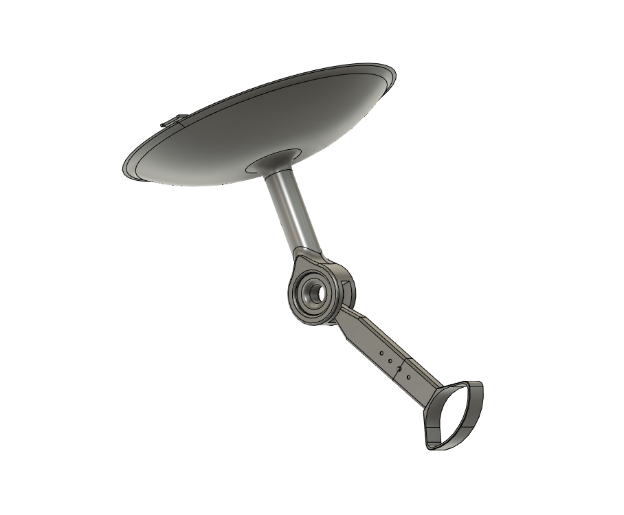
In this project, following the initial creation of a rigid body, I went back and added the length adjustability factor for the bottom support or pylon structure, as I realized this would make the implications for this product higher. Being able to secure one of these to your pet without the worry of having a much smaller or larger size compared to the pet's other limbs for both the human and the animal to have the most utility from it.
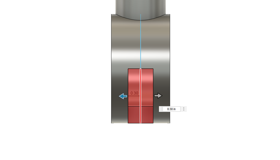
- Create a division line and extrude into cutting in order to narrowly define this split and adjustability line
- stablish the downward thickness with which you will have to create the inside piece and create circles around the outside surface that extend downward, one of which has the push button aptly applied.
- Add the button and create the holes and ensure that it seems to be the proper configuration from afar
- Lastly, create holds and add some cylinders within the first and second support system, as this is the are where potential energy sources particularly rubber bands can be used to bring the prophetic back to equilibrium and provide more passive support and strength to the movement itself.
- Additionally, go back on the top of the bowl and add two rectangular protrusions that could be used for this to become a tool that people can have and a string can be attached to keep this device with you in as many situations as possible.
Downloads
Conclusion
At the end of the day, there are hundreds to thousands of different canine and felines and other pets that have a disability and they need to be properly cared for and supplemental so that they do not have to suffer the harsh consequences that might come with their disability. I hope to deploy this product in an experimental sense and then provide it to those that need it for their pet especially during this time and I hope to continue pursuing this task and bringing some physical execution and implementation of this project to better the life of so many animals.