Adding Status Lights to the XRV Kit With the Fungineers Stompies Footpad
by tcm0116 in Workshop > Electric Vehicles
1583 Views, 3 Favorites, 0 Comments
Adding Status Lights to the XRV Kit With the Fungineers Stompies Footpad
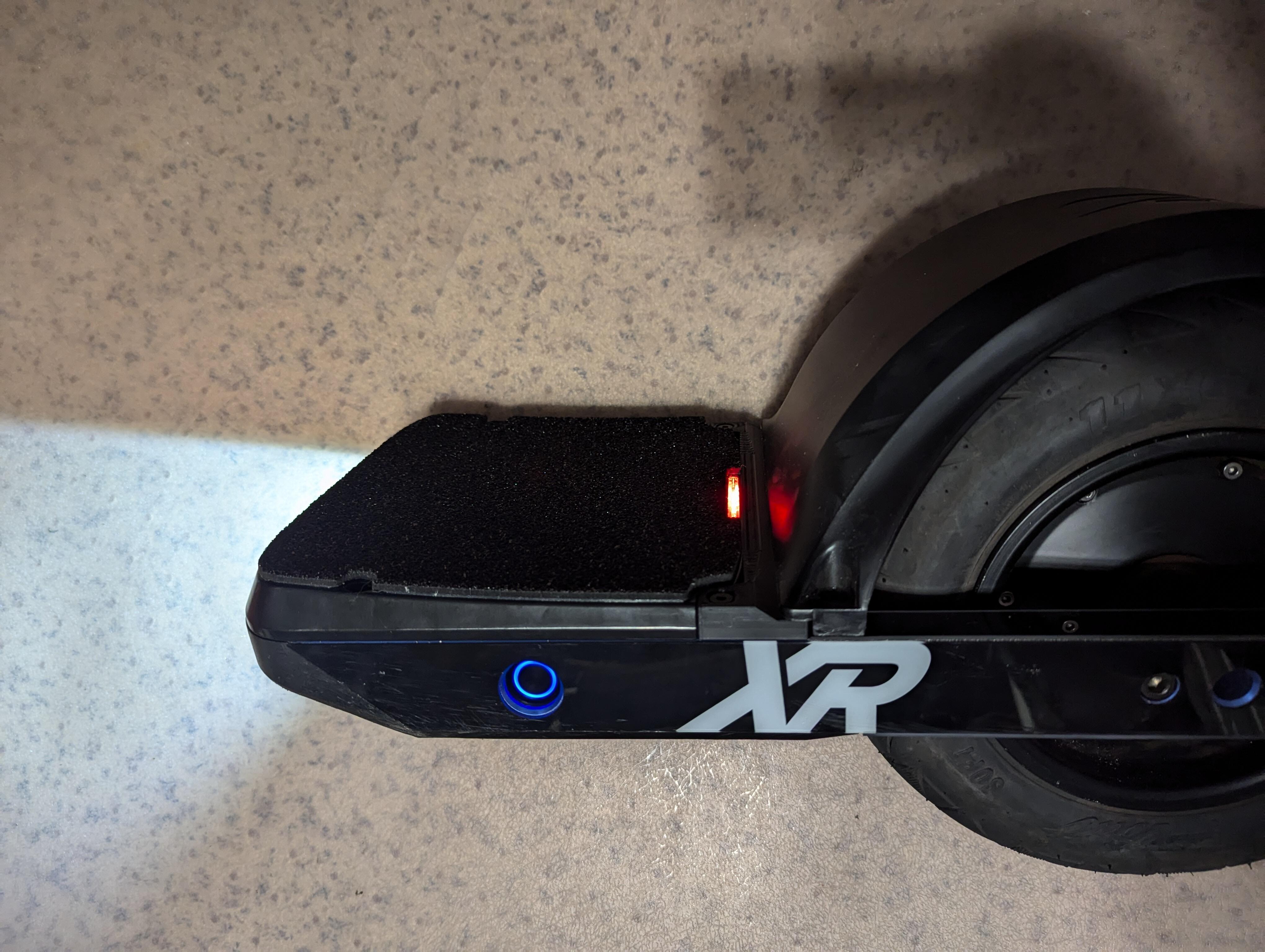
After installing the Floatwheel XRV kit, I really wanted to add status lights to my board. I discovered that the Fungineers Stompies frootpad has a slot for the lights to illuminate through, so I decided to work on a mod to install status lights into my board.
Supplies
- Onewheel XR with Floatwheel XRV Power Kit installed
- Fungineers Stompies Sensor Footpad
- ZJPT connector - Z108-6A
- WS2812B LED Strip with 6.5mm spacing
- 24 AWG Stranded Wire
- 0.1" Male Header
- 3/32" Heat Shrink Tubing
- 3/16" Heat Shrink Tubing
- 1/2" Double-Sided Film Tape
- J-B Weld ClearWeld Epoxy
- Clear Silicone Sealant
- GH1.25 Connector Kit
- 3/8" 10-32 screw (short XR footpad screw)
- Fungineers Stompies Footpad XR Close Out with LED Status Light Holder
- Soldering Iron
- Solder
- Flux
Controller Wiring
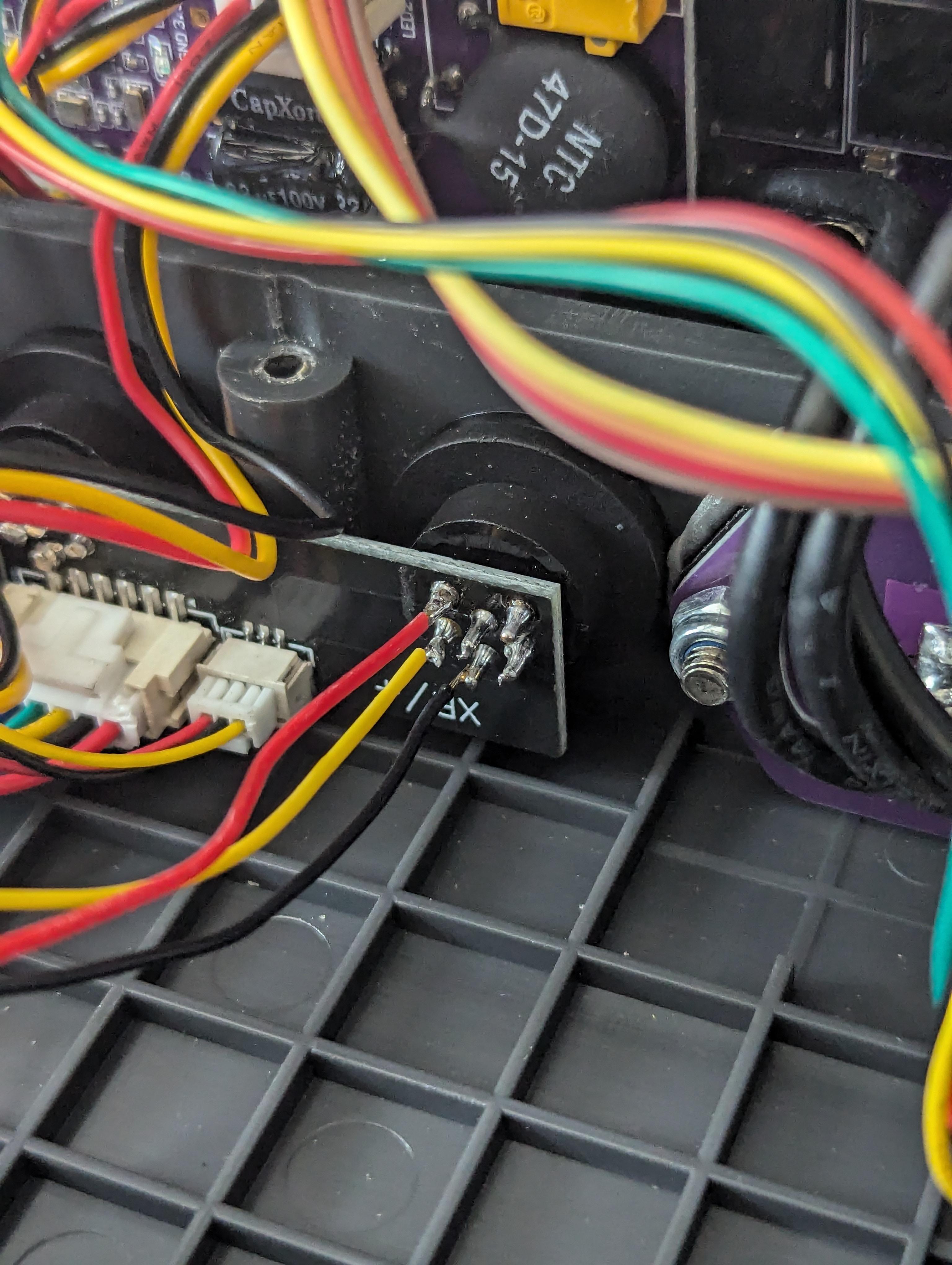
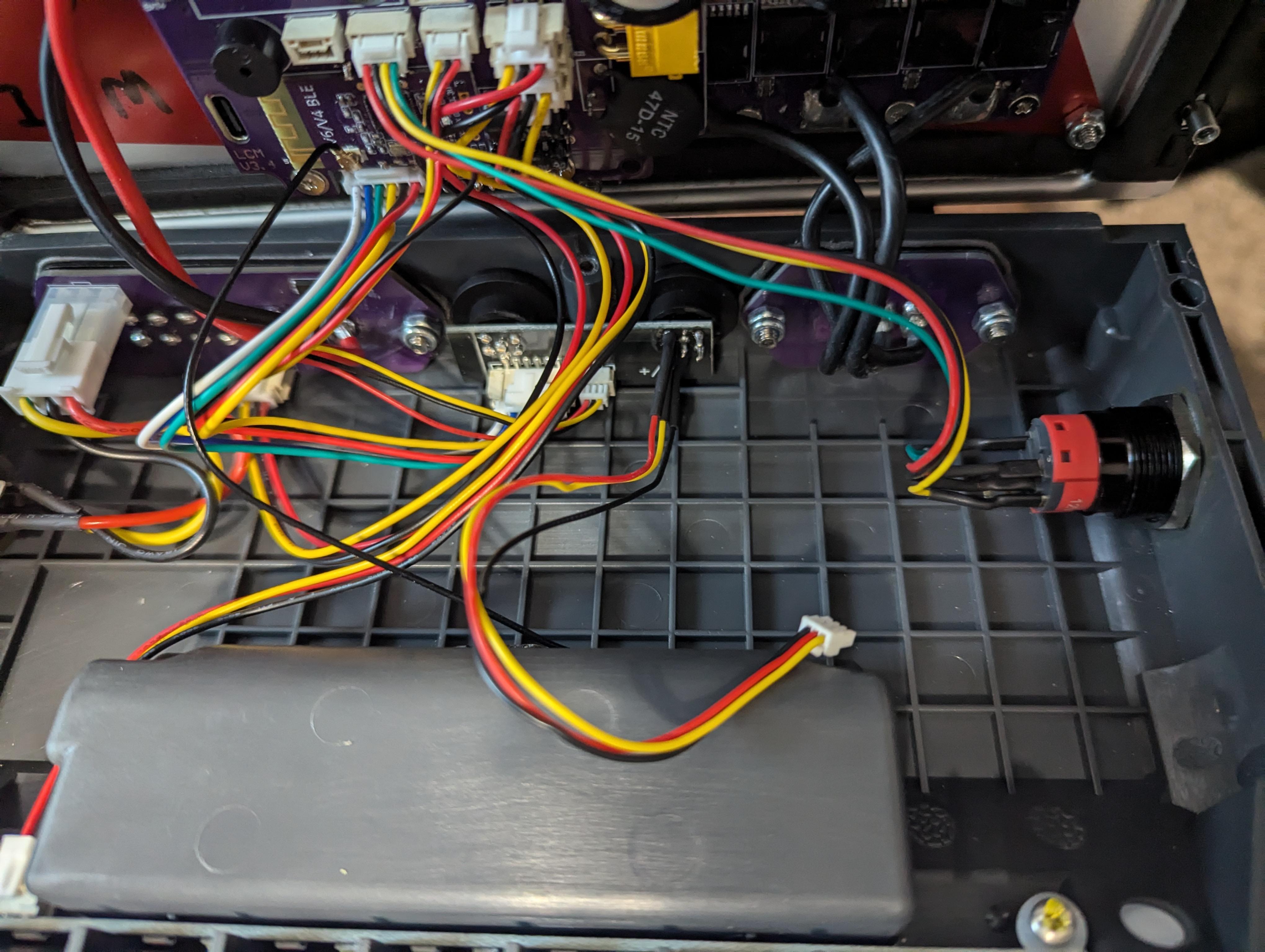
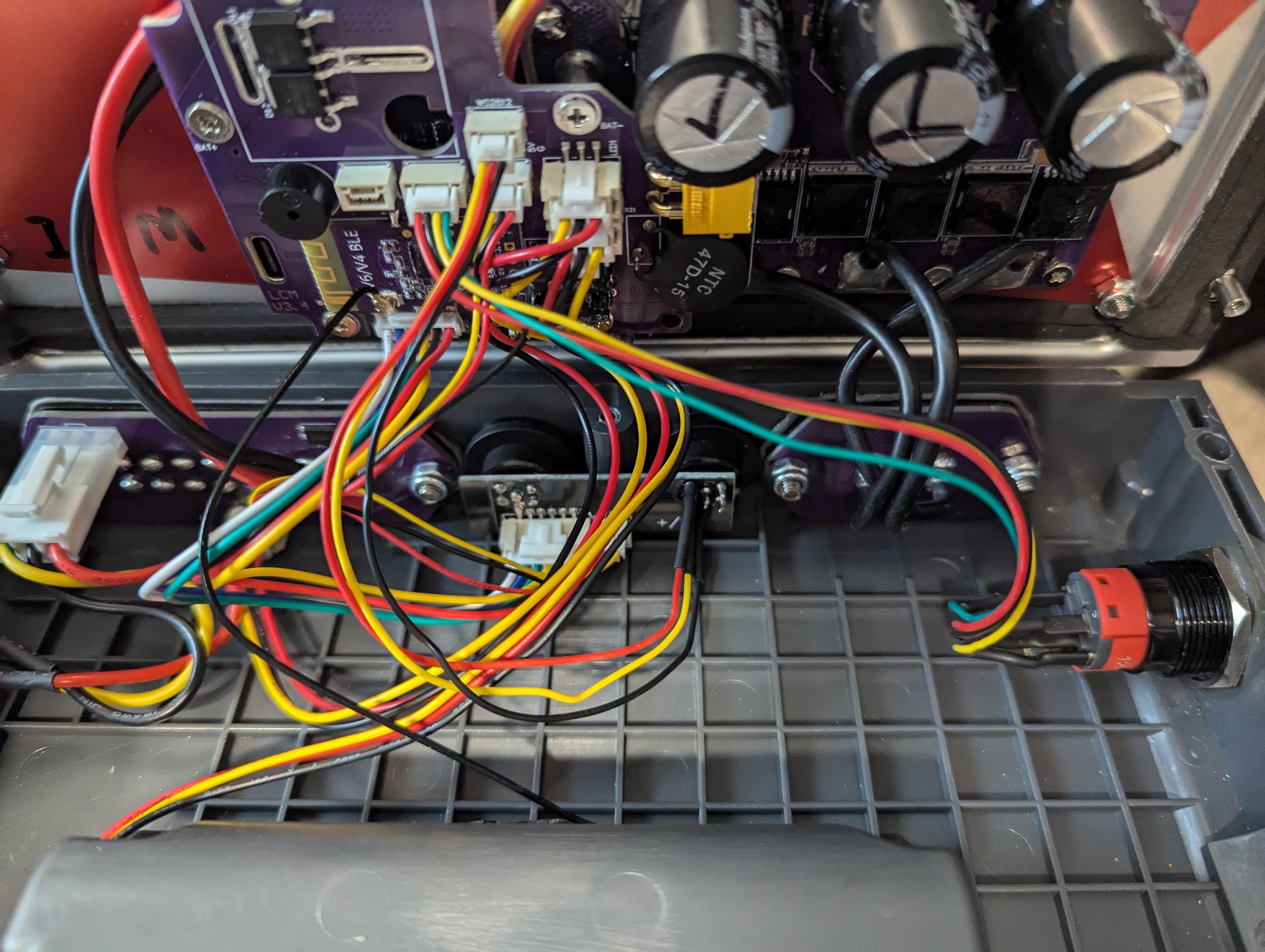
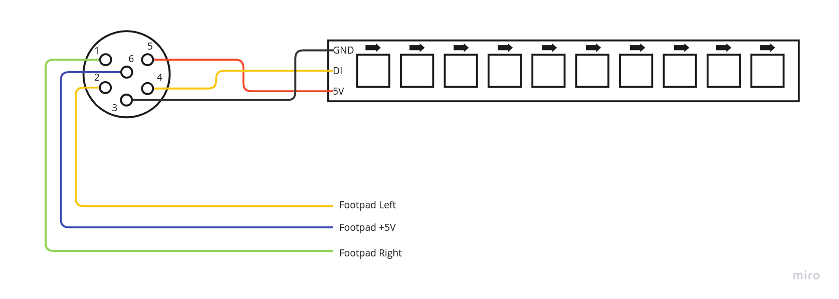
The footpad connector for the XR only uses 3 of the 6 pins, which leaves 3 unused pins that can be used for the status light wiring.
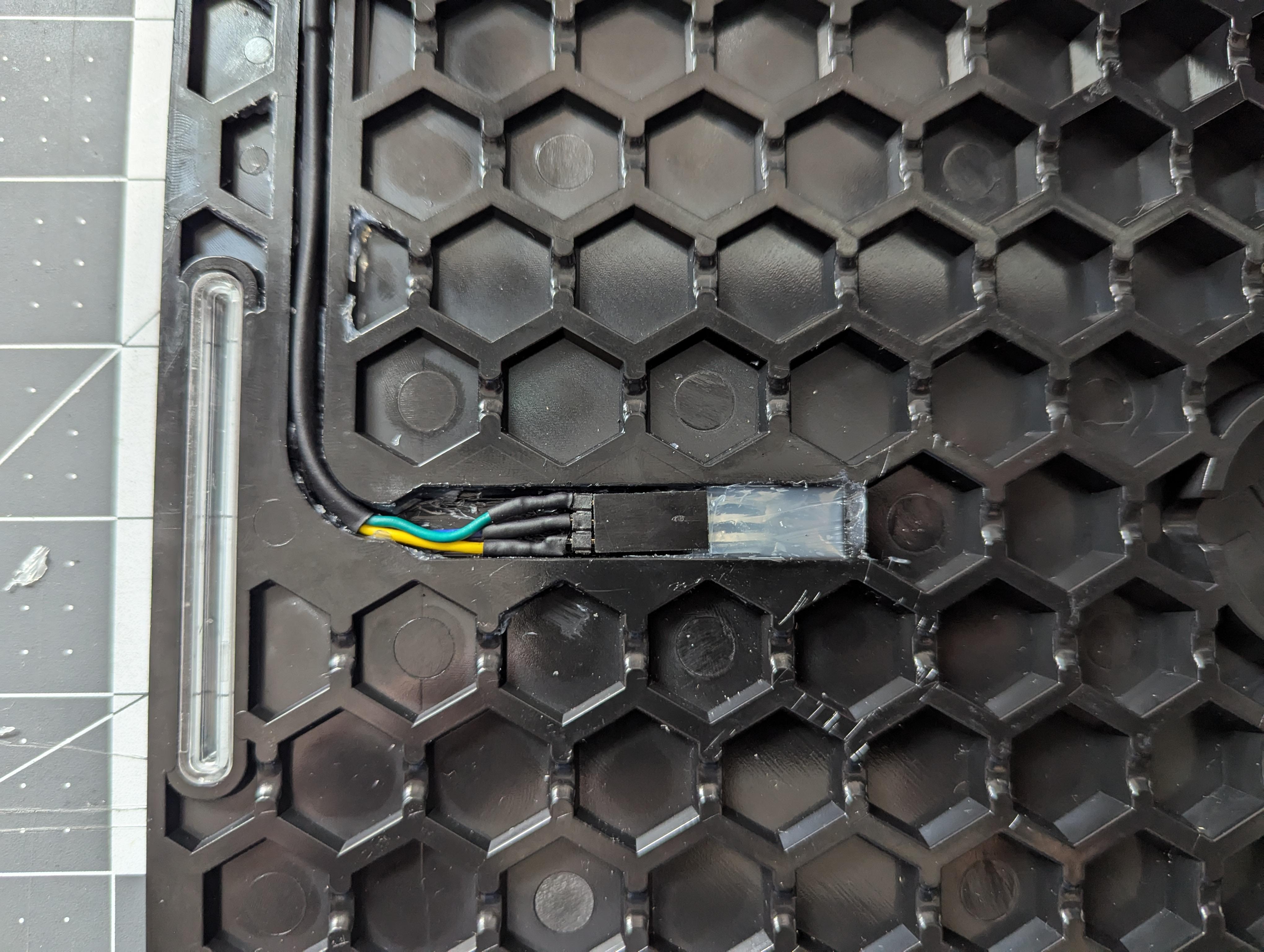
Using a 3 pin GH1.25 connector, install a yellow, red, and black wire going left to right when plugged into the "WS2812" connector on the XRV controller board. Then, carefully solder the wires to the leads on the footpad connector as shown (Pin 3 - Ground, Pin 4 - DI, Pin 5 - 5V).
Footpad Wiring Harness
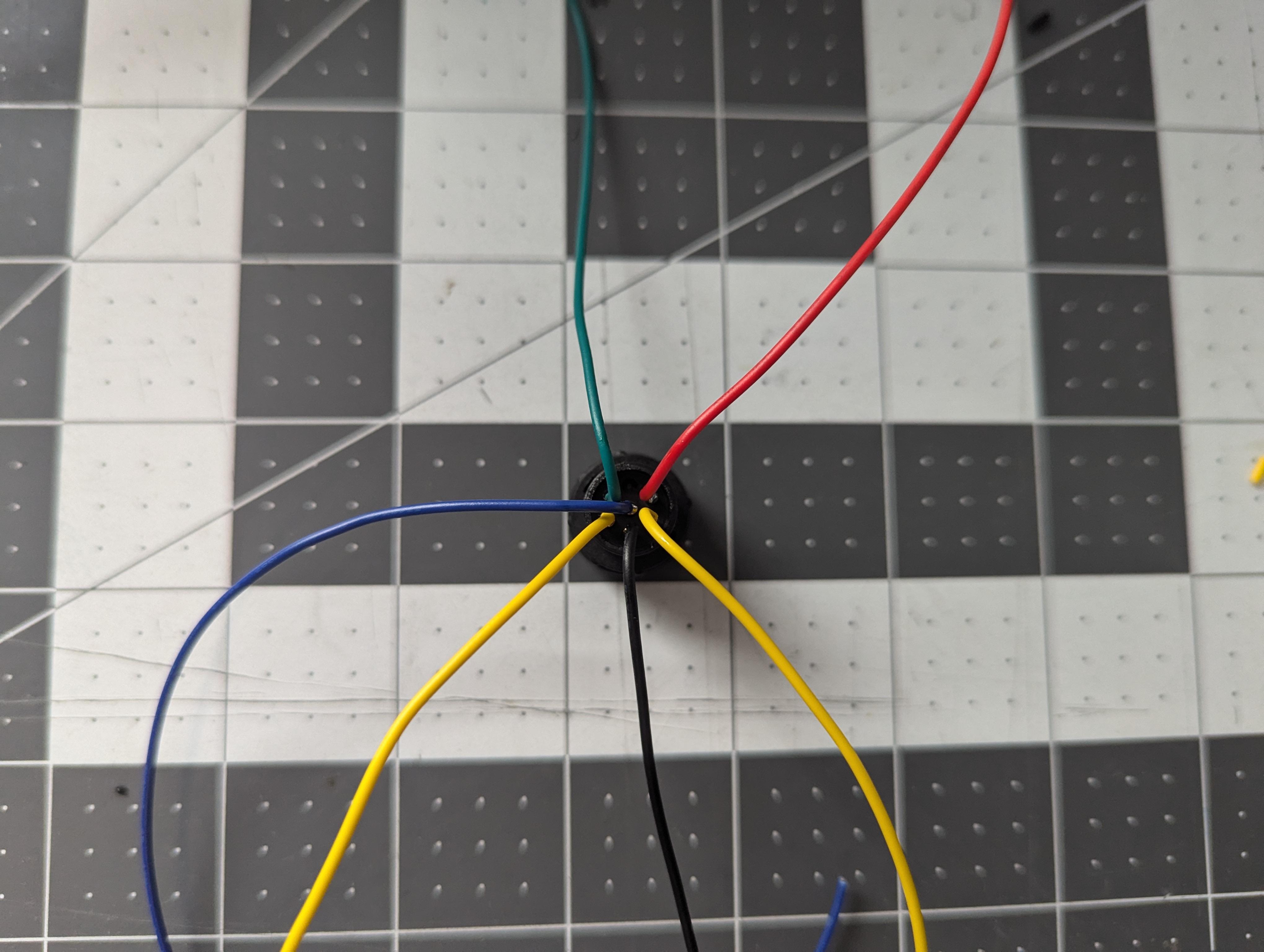
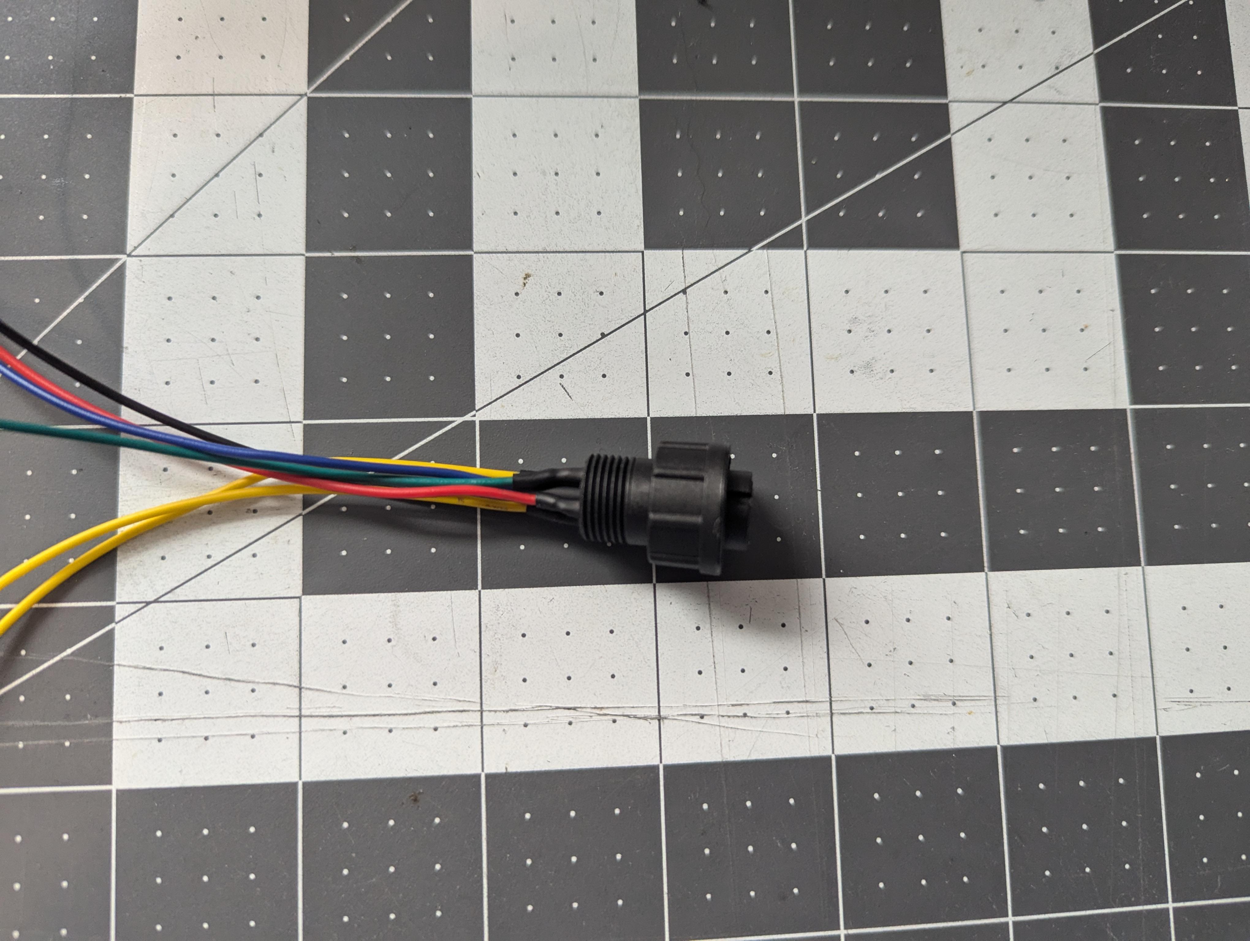
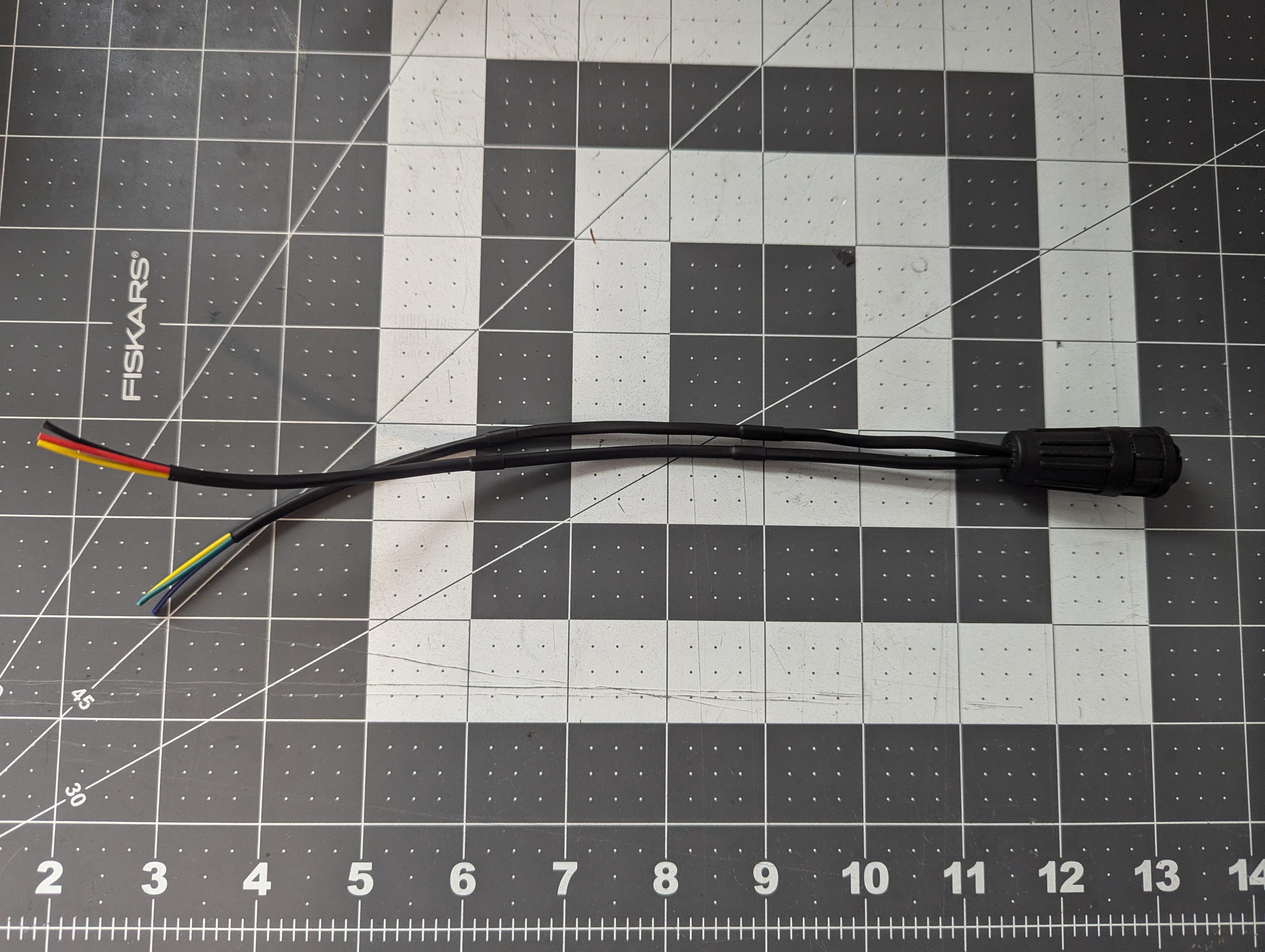
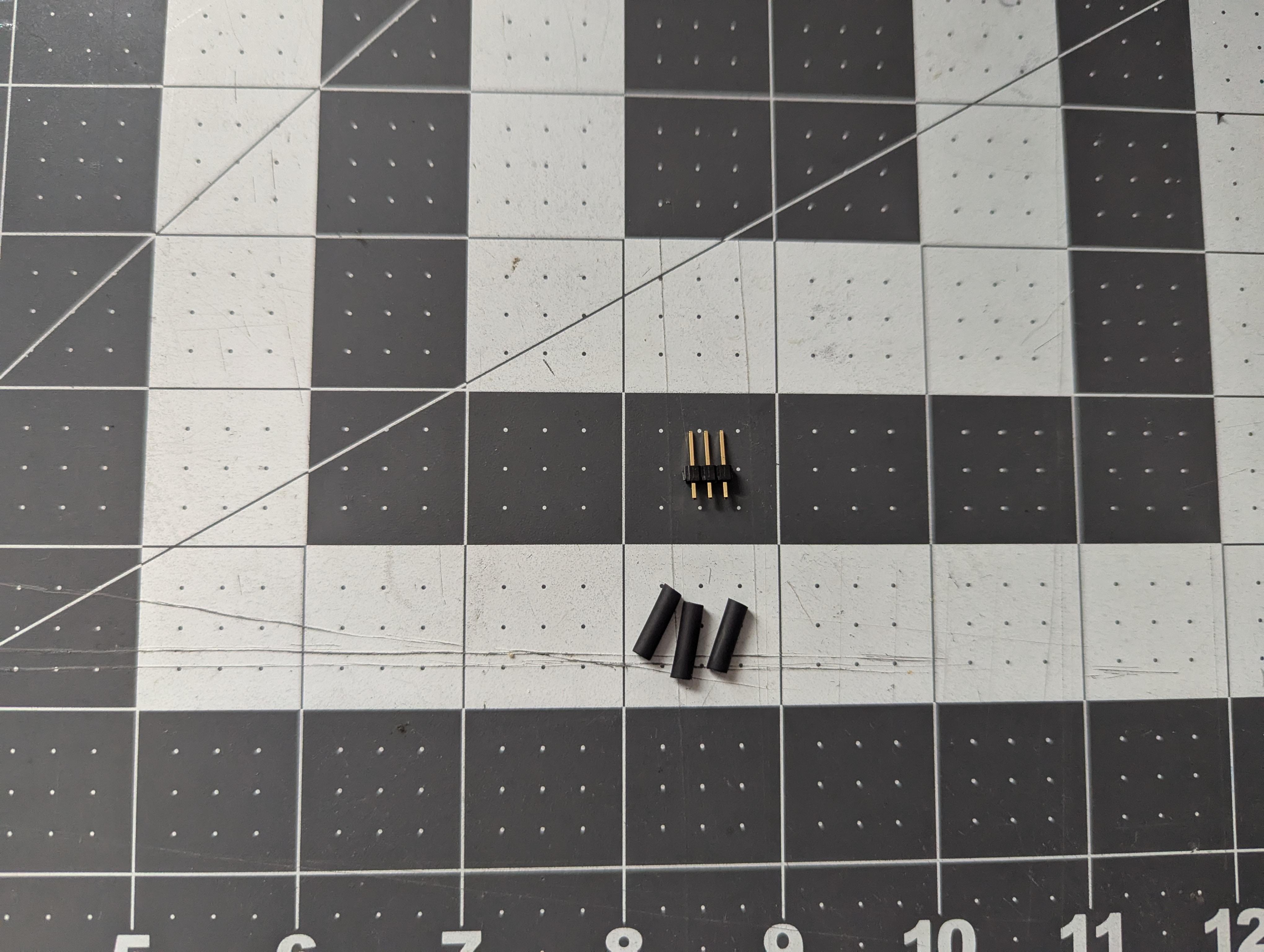
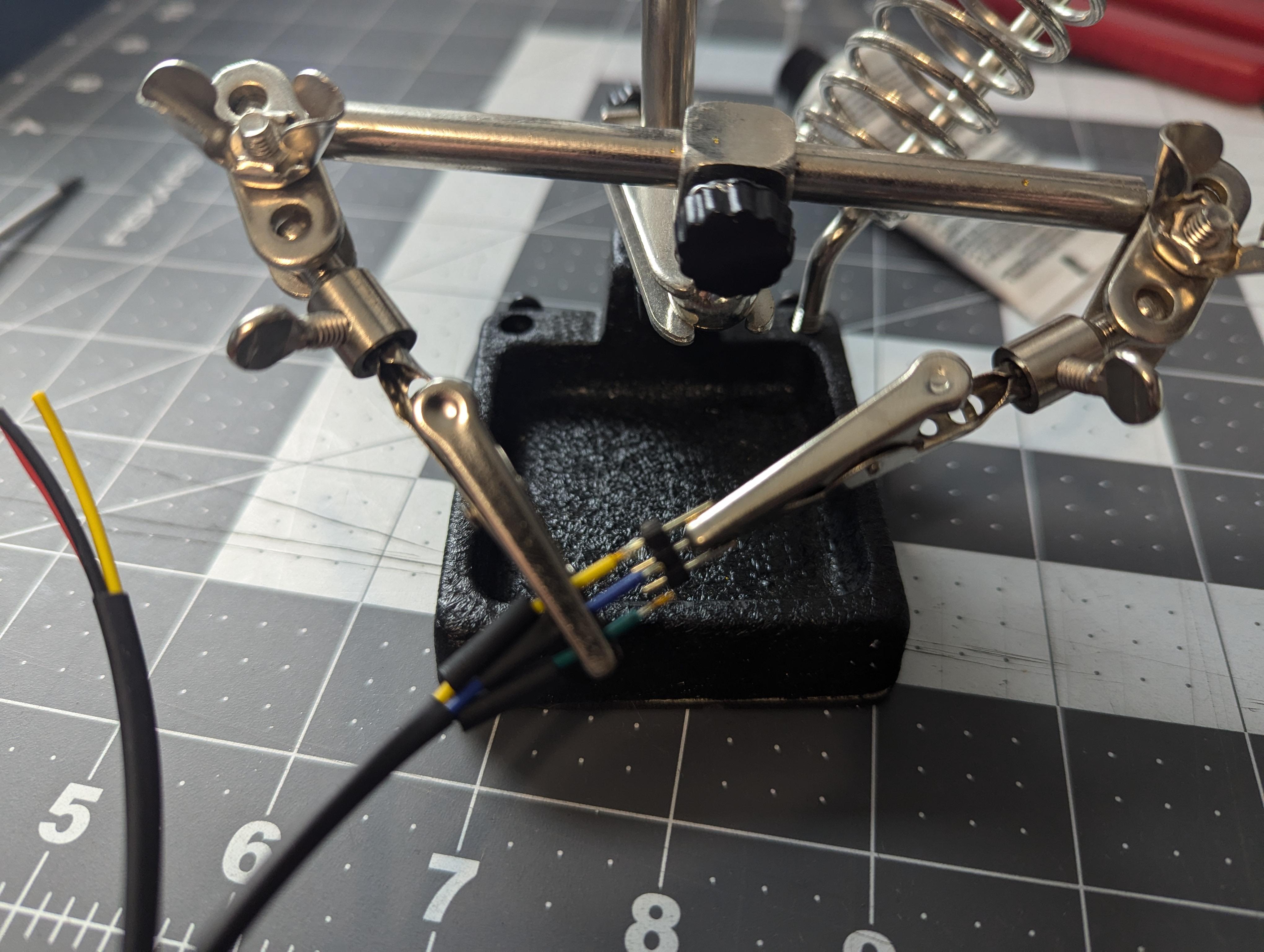
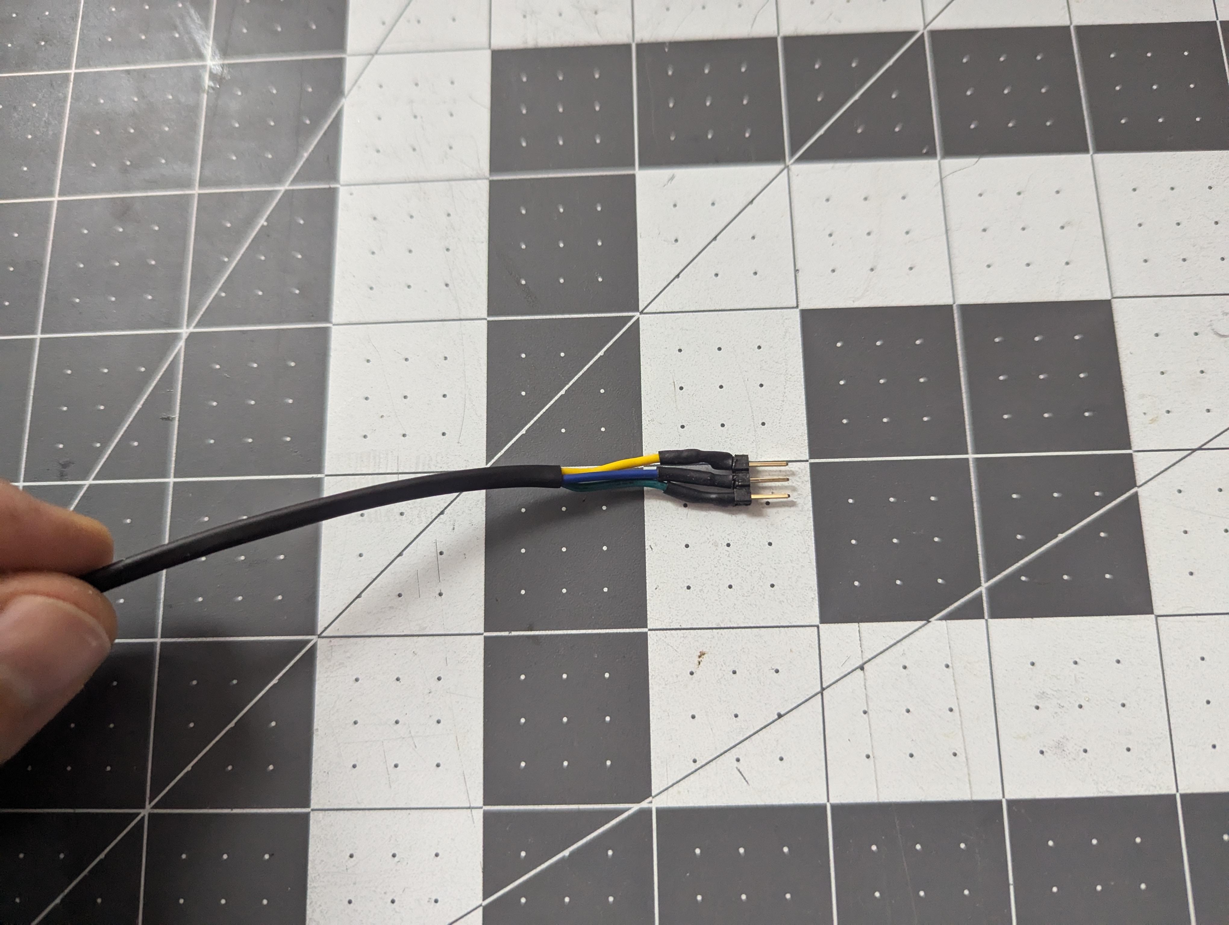
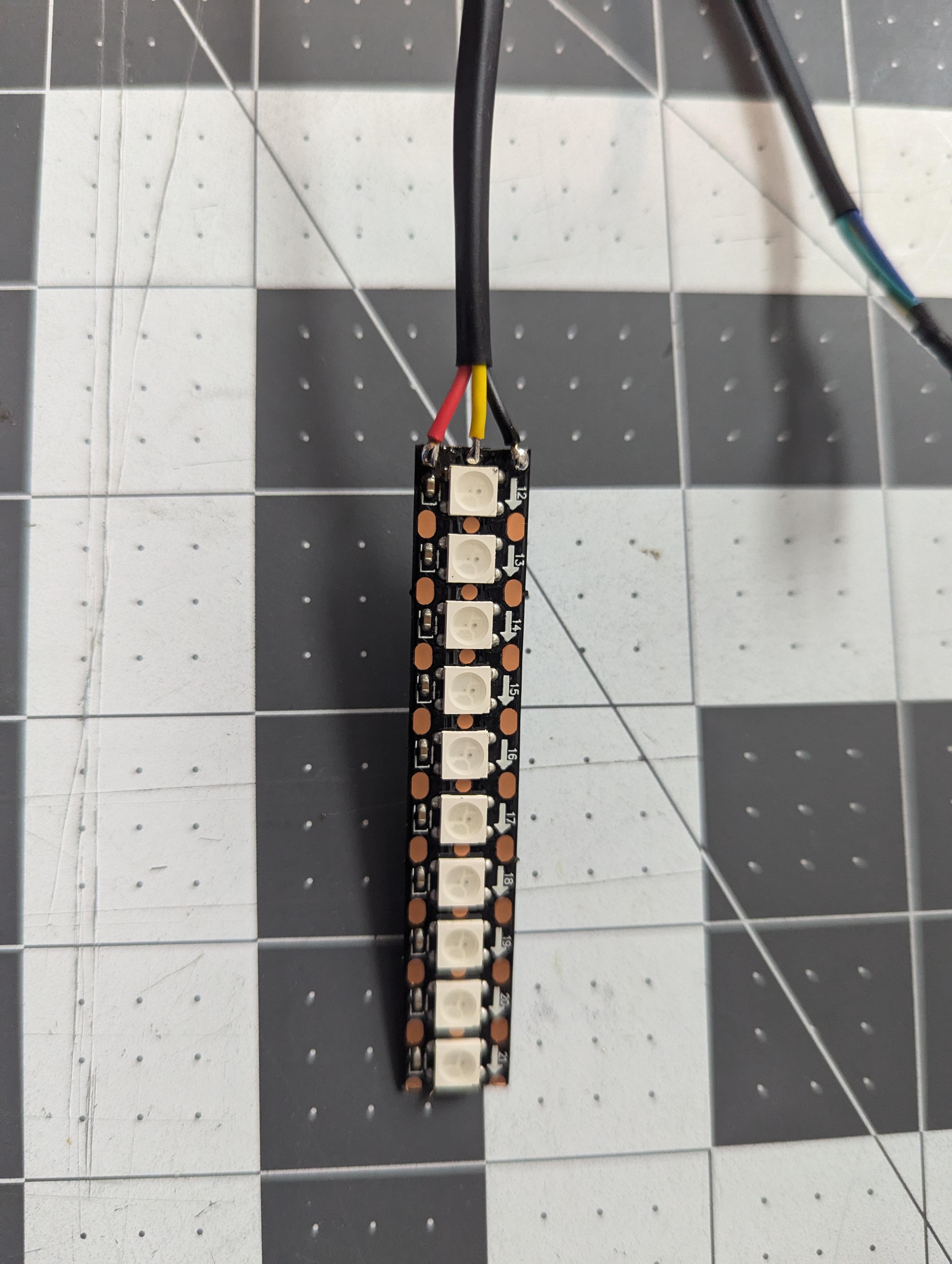
Build the wiring harness as shown.
The LED strip is much longer than needed, but can be cut down to the appropriate length containing 10 segments. Be sure to leave enough of the solder pads exposed on the input side (the side the arrows are pointing away from) to solder the connections.
Test the Wiring Harness
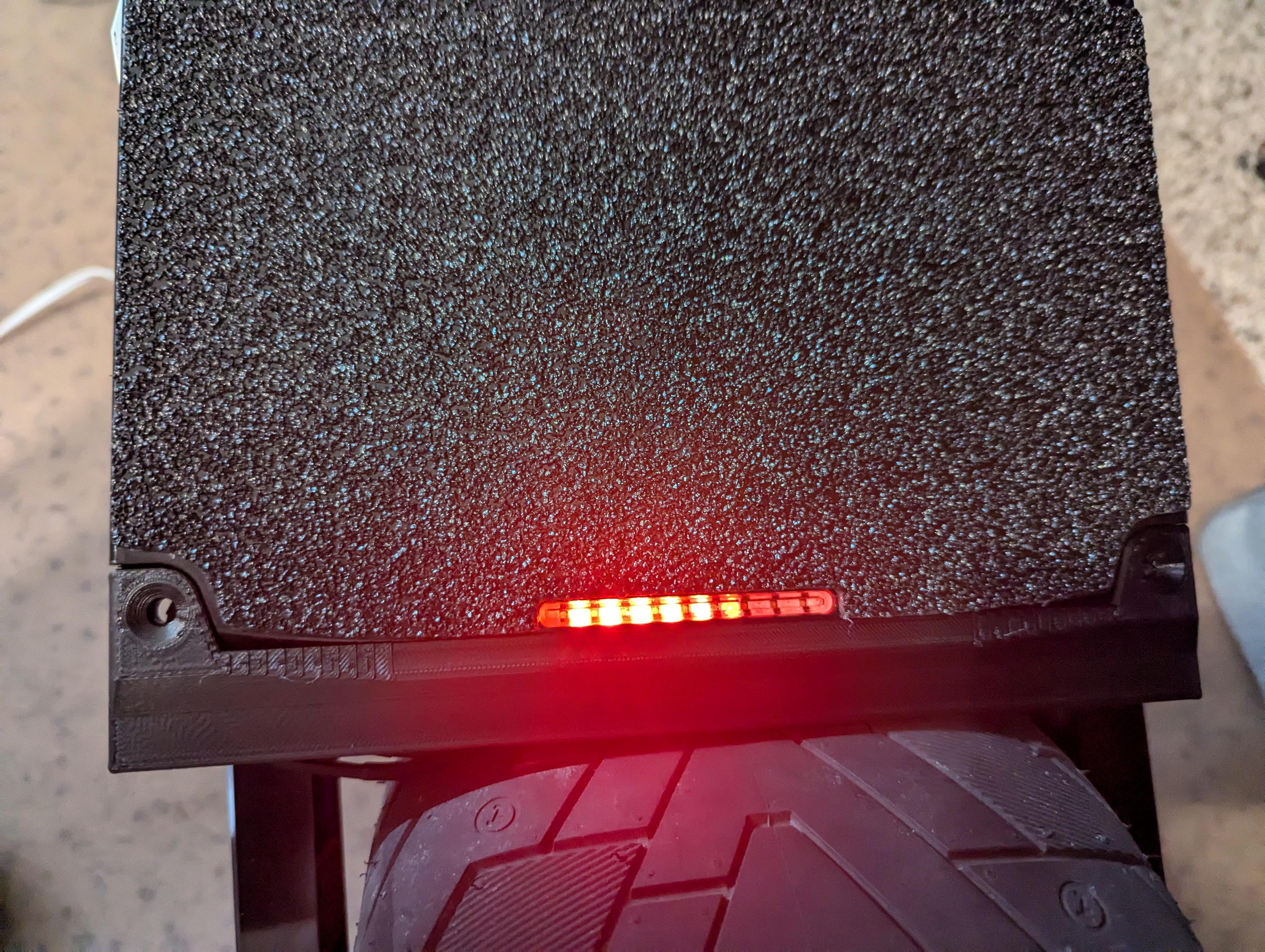
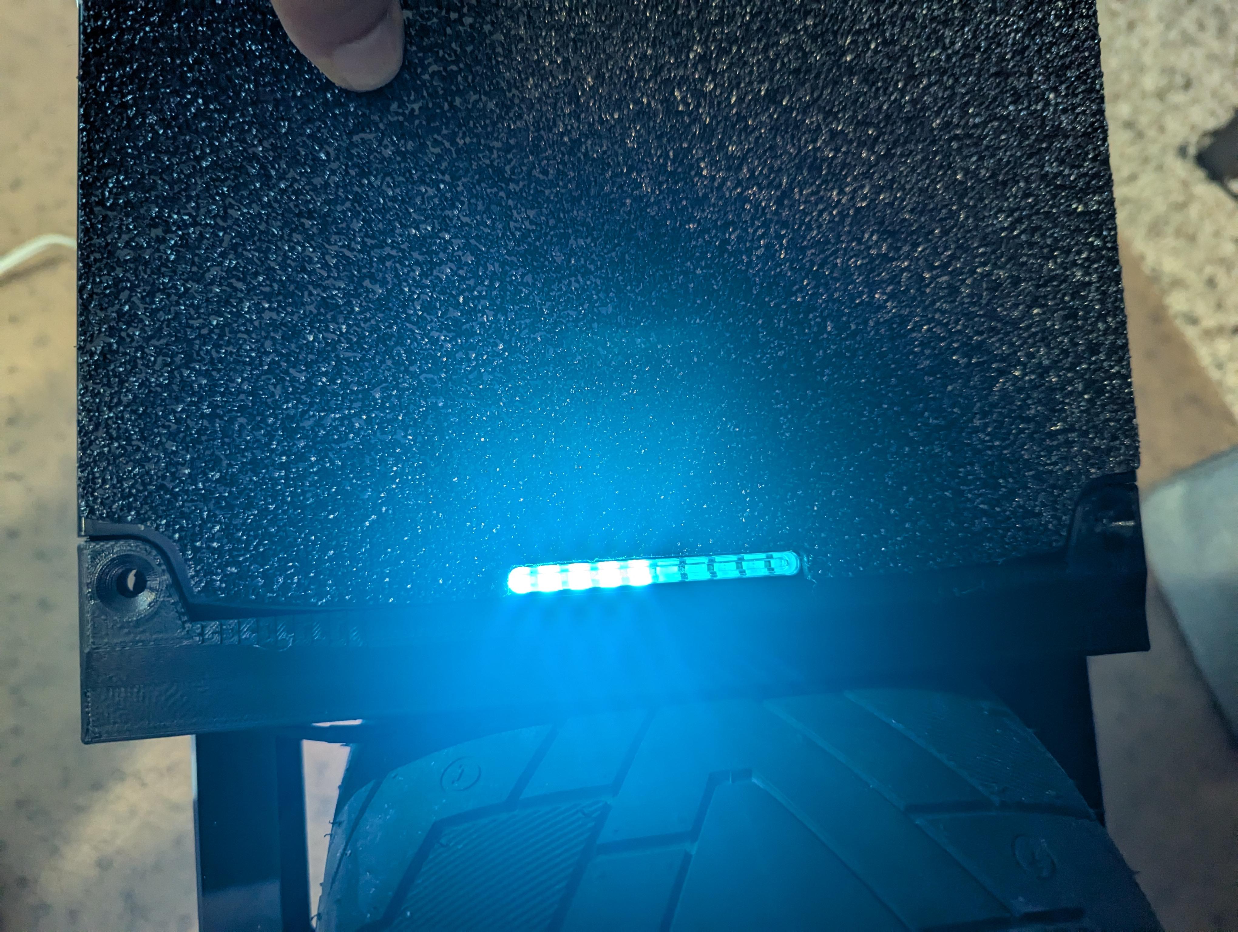
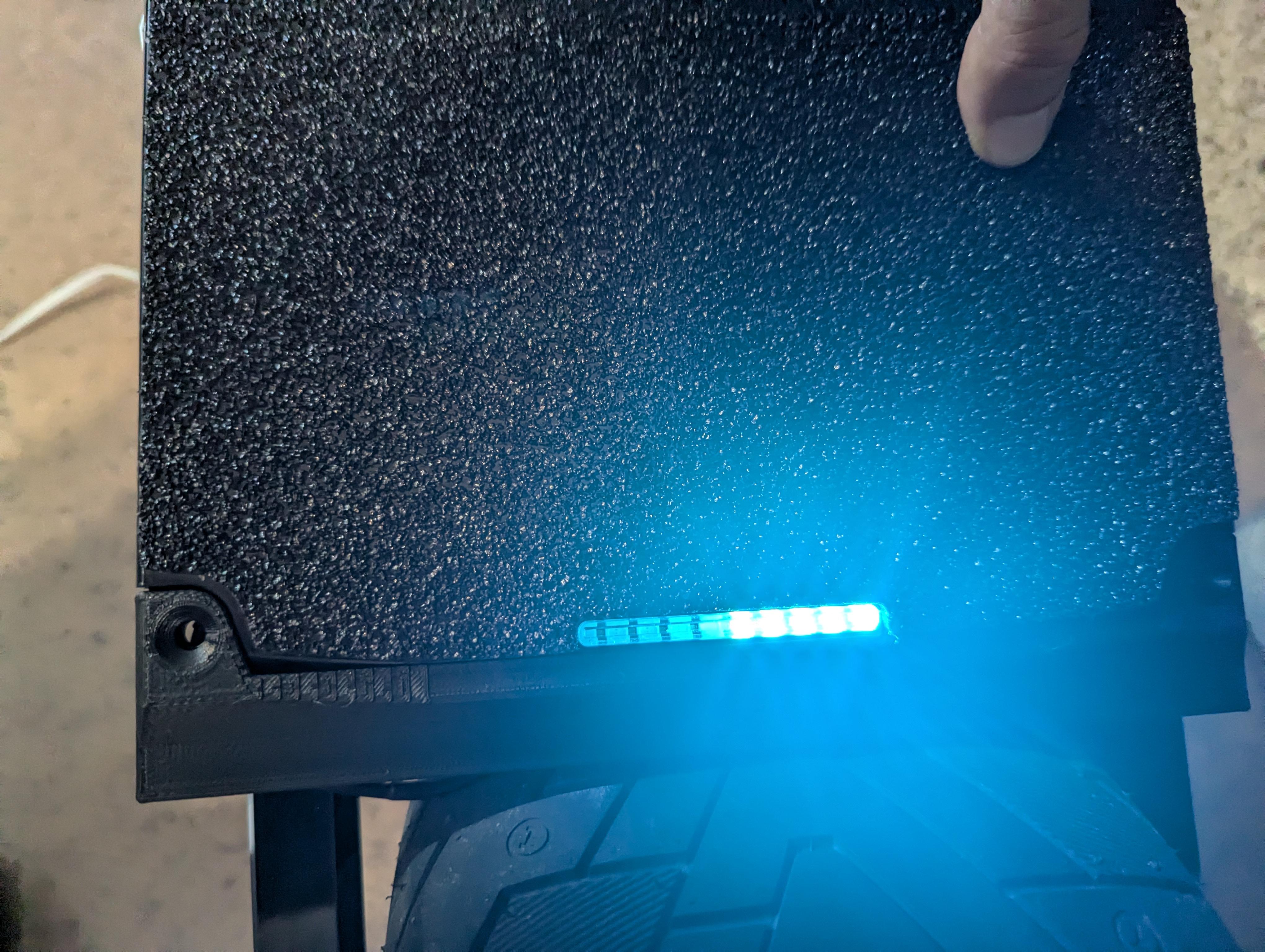
Connect the wiring harness to the footpad and to the controller. Power on the controller and verify that the LED strip illuminates and is reactive to pressing on both sides of the footpad.
Install LED Strip Into Holder
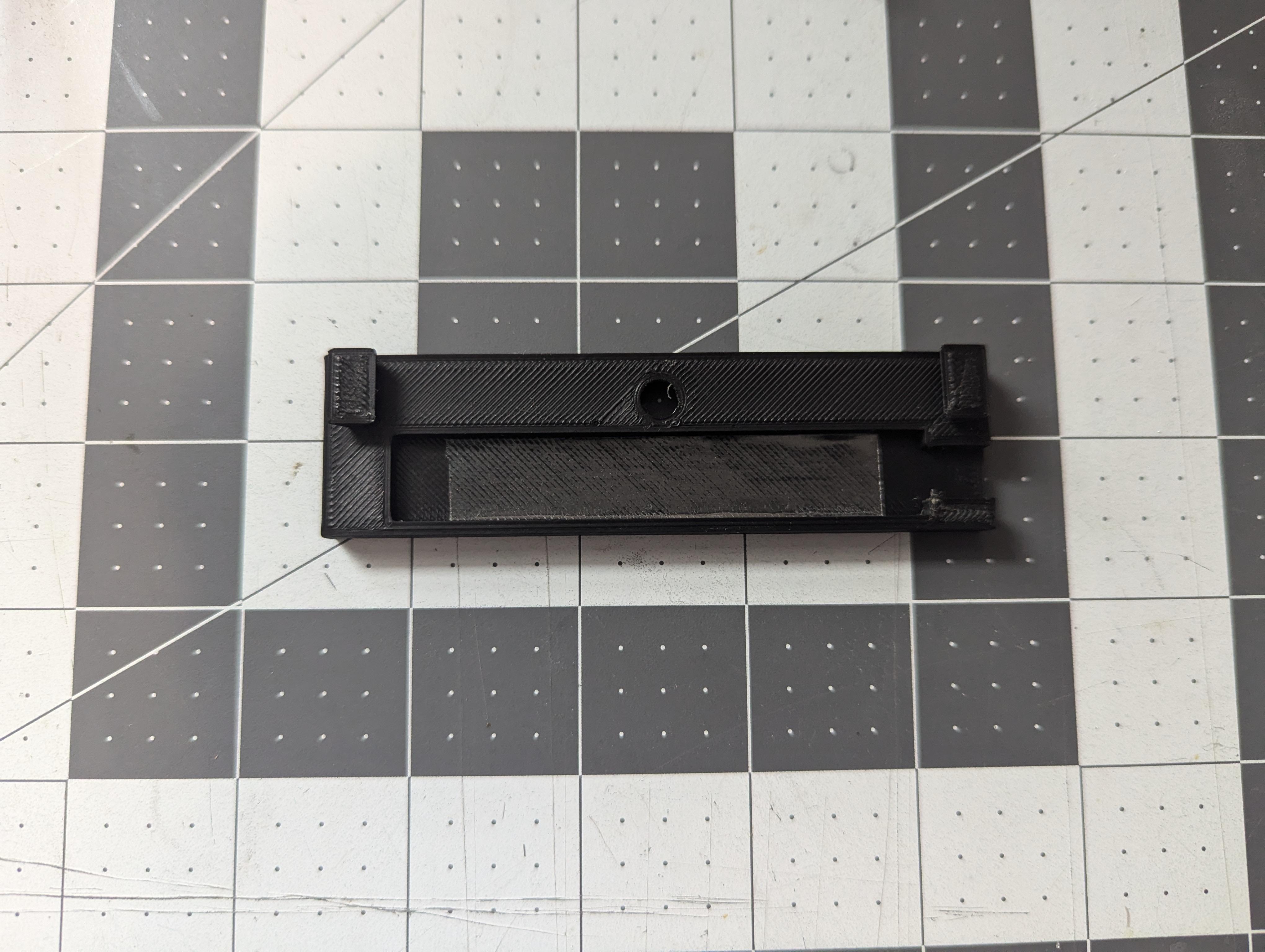
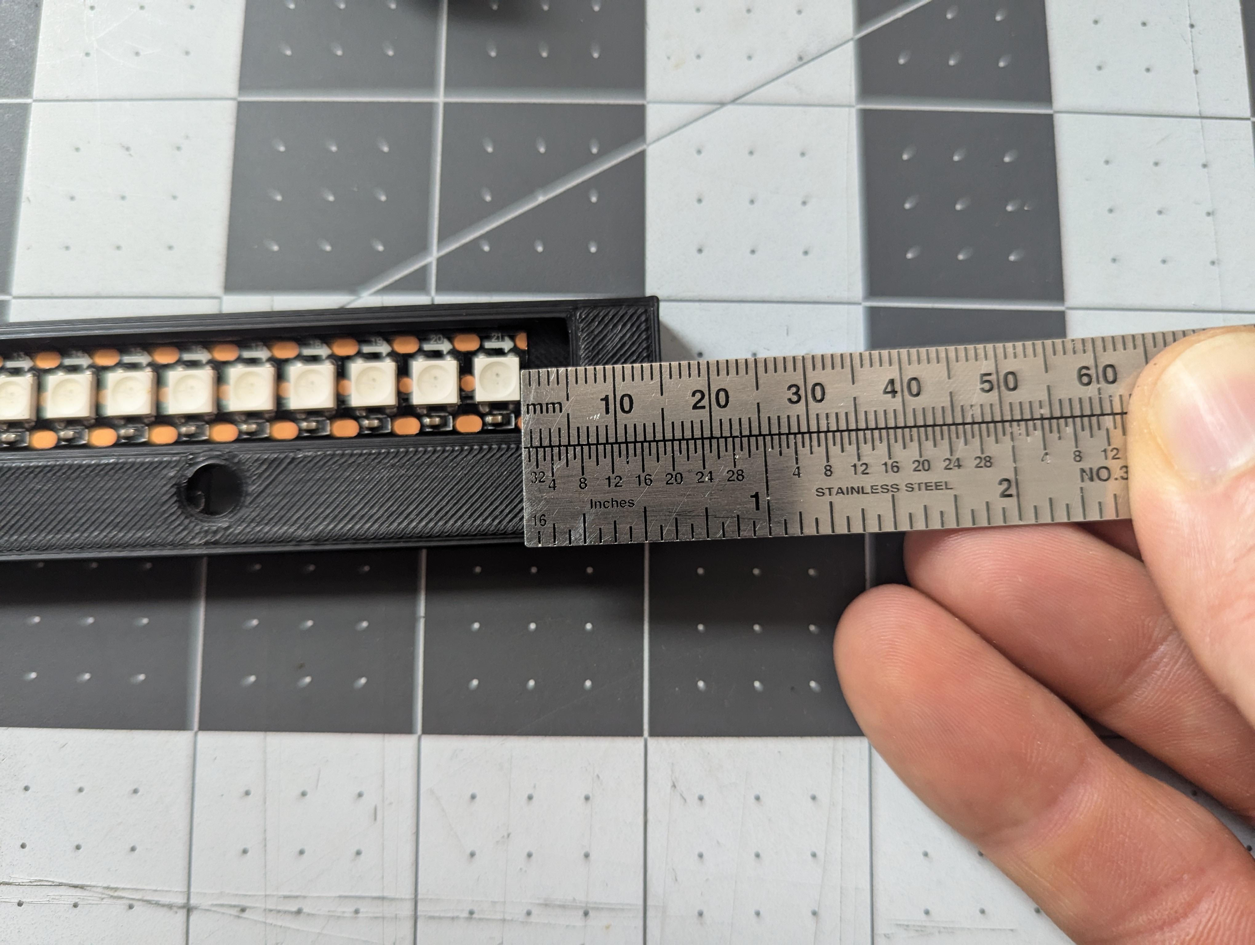
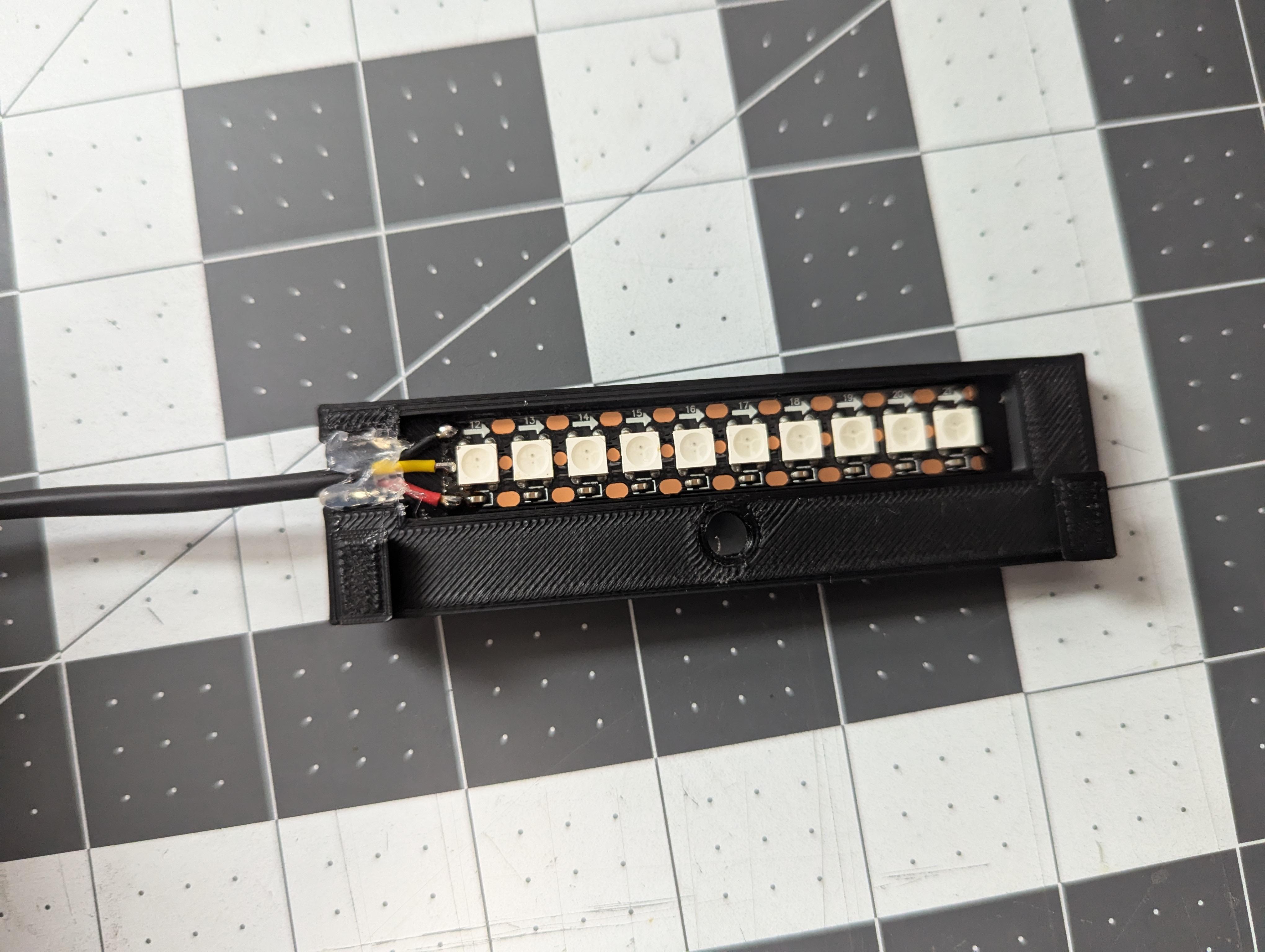
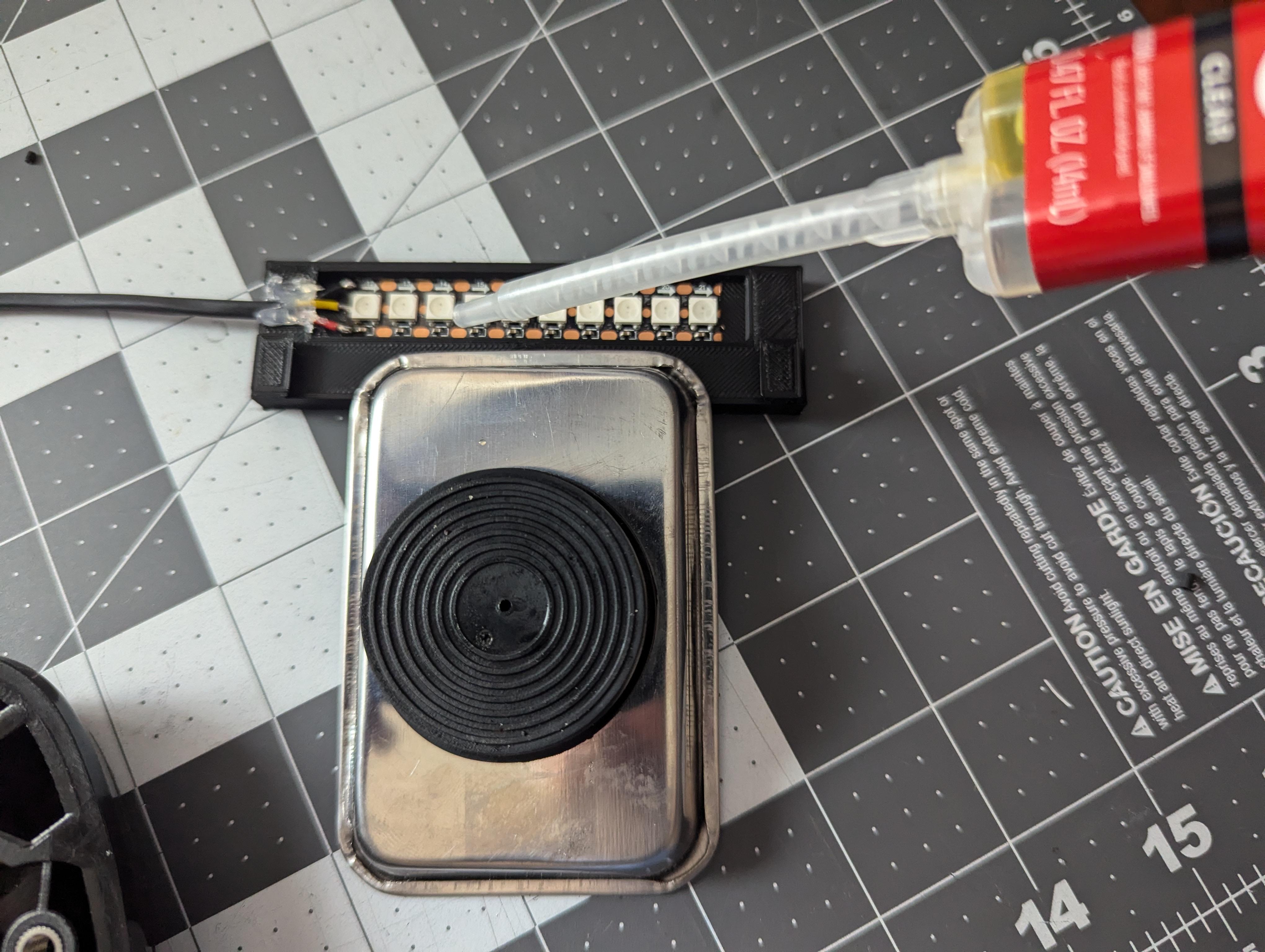
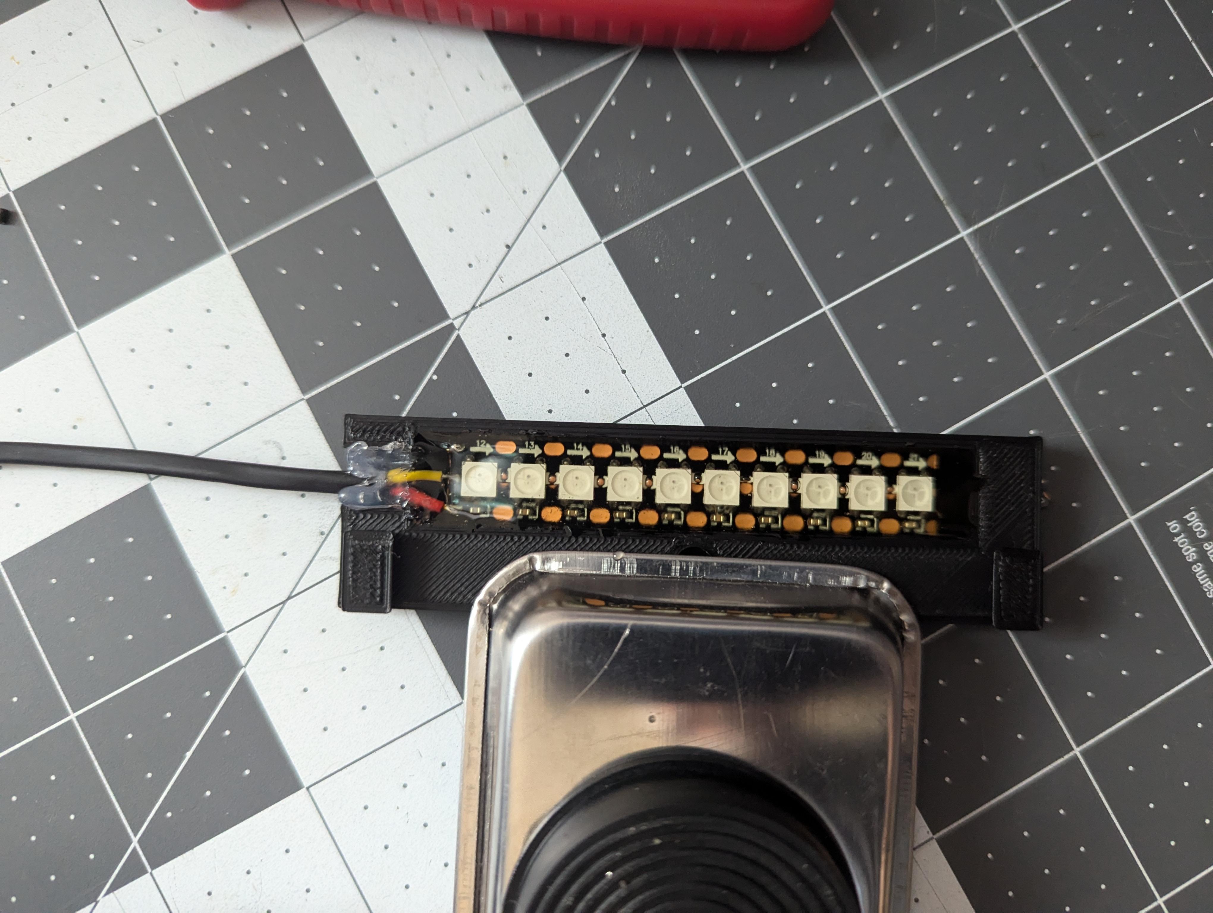
Using a strip of the 1/2" double-sided film tape, place the LED strip into the holder, being sure to center it. Apply a small amount of hot glue around the cable to prevent the epoxy from spilling out. Once the hot glue is dry, apply the epoxy to fully seal the LED strip, being sure to not over-fill. The epoxy will start to harden in 5 minutes, but wait at least an hour before proceeding.
NOTE: Be sure to apply the epoxy in a well ventilated area.
Install the Wiring Harness in the Footpad
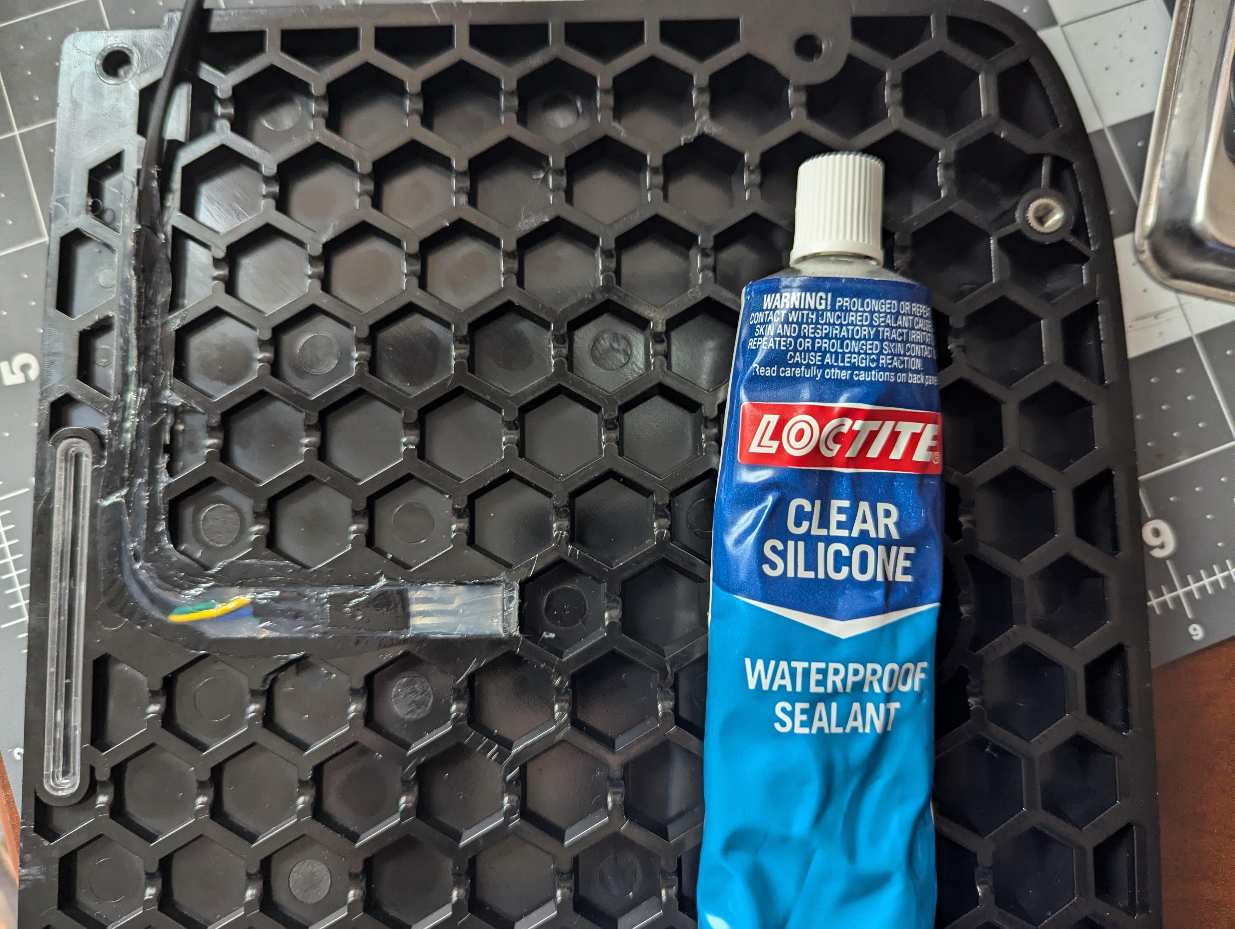
After verifying that the footpad is connected in the correct left/right orientation, Use a small amount of clear silicon to install the wiring harness into the footpad. A plastic spoon works well to smooth it out. Let cure for several hours.
Final Assembly
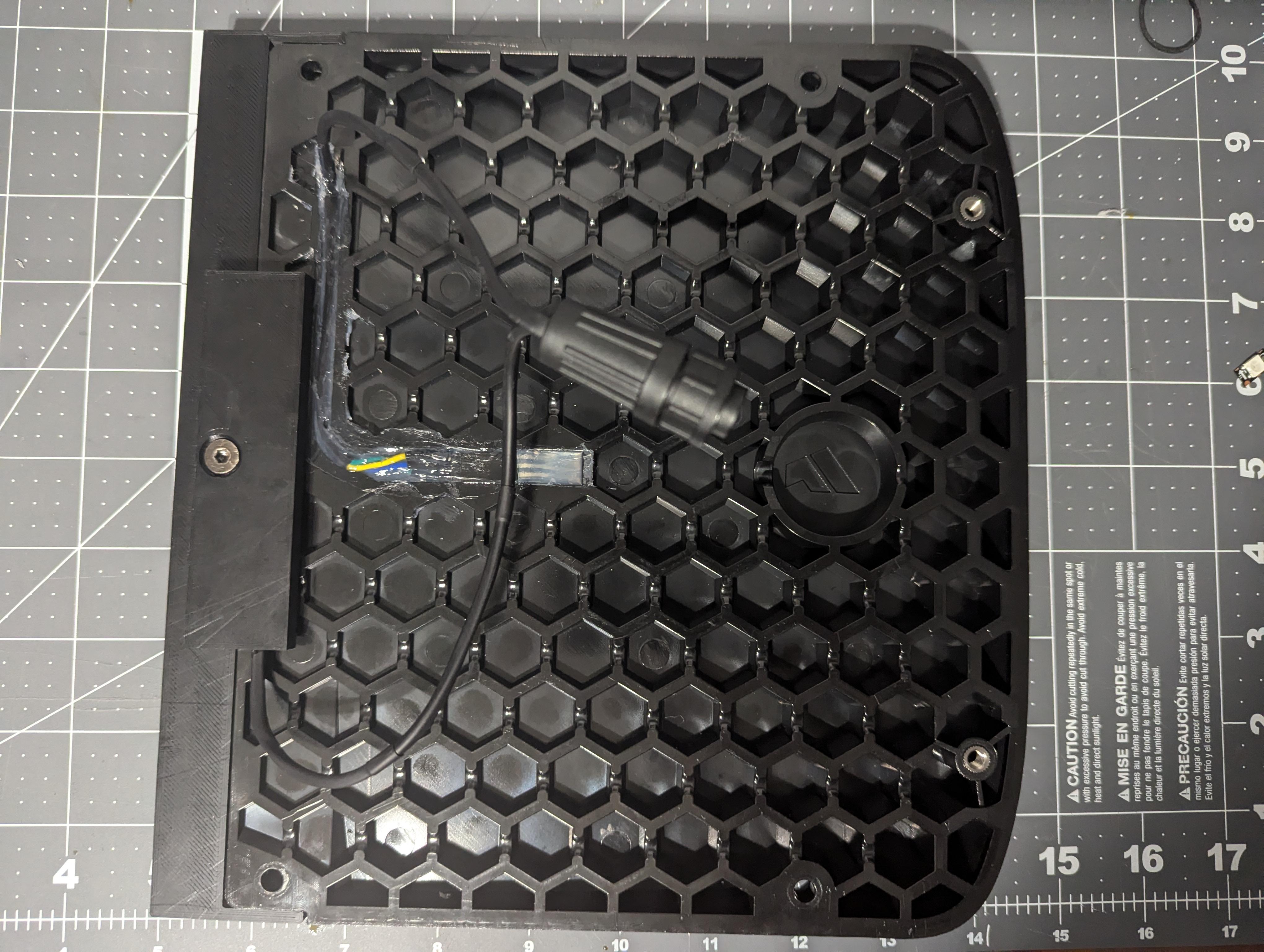
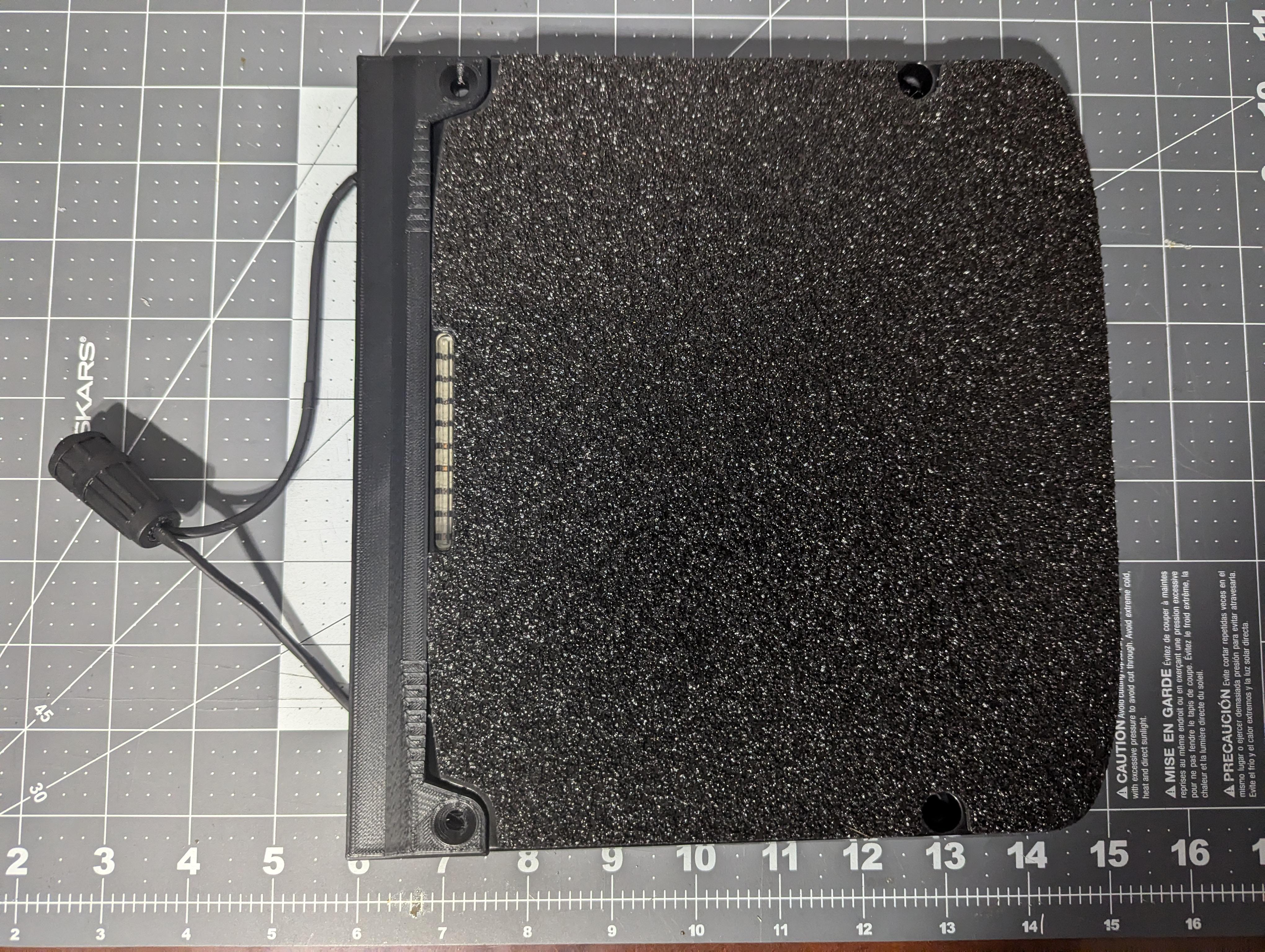
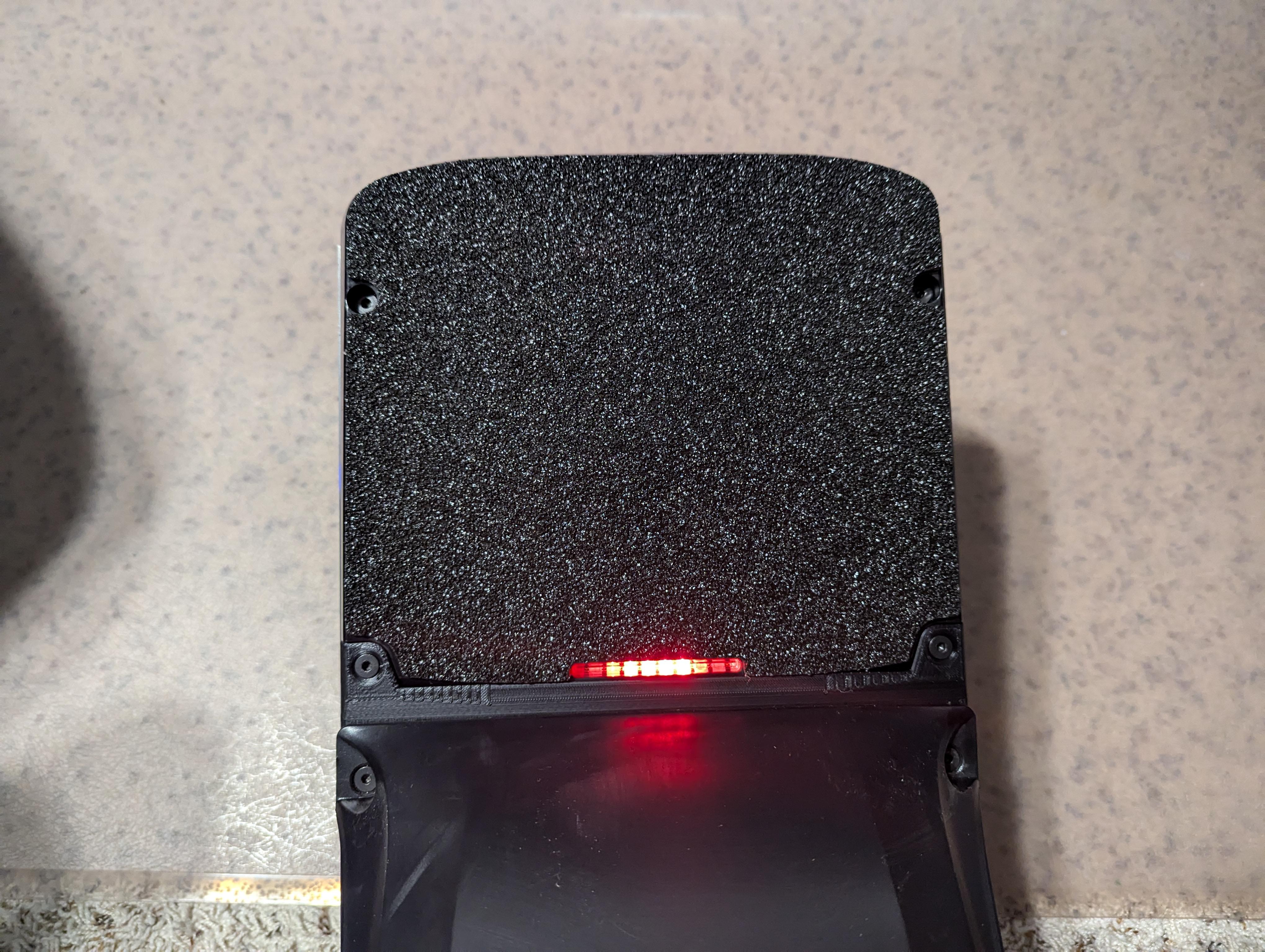
Install the LED holder onto the closeout, using a 3/8" 10-32 (short footpad screw) to secure it in place and then install the foodpad onto the board. Power it on and enjoy the new status lights!