Adding Another Dimension to the Rubik's Cube
by dilanmehta1 in Workshop > 3D Printing
4930 Views, 41 Favorites, 0 Comments
Adding Another Dimension to the Rubik's Cube
The Rubik's Cube is a seemingly innocent toy that is responsible for an immeasurable degree confusion and frustration upon mankind, so why not make it harder?
Although the puzzle is undoubtedly a source of irritation, Erno Rubik, the inventor of the puzzle, was not an evil mastermind plotting to frustrate mankind; as a Hungarian professor in the field of engineering, he originally built the pieces by hand out of wood to demonstrate three dimensional design to his students. His profound effort to go above and beyond for his students ultimately left an indelible mark on the world when it became the most ubiquitous and iconic toy of all time. Although the toy was "in fashion" during the 1980s, currently, various companies compete to design and sell puzzles of all shapes and sizes.
In this project, you will learn how to design and 3D print a Rubik's Cube that changes shape when scrambled. The design process is an extremely arduous task, so you can either design the parts using the step by step guide if you are up for a challenge or you can simply download the STL files here: https://drive.google.com/file/d/1XlUmitYI4lzwTdshM..., read through the first two steps, and then skip to step 22.
Please watch this video before going any further to introduce the steps:
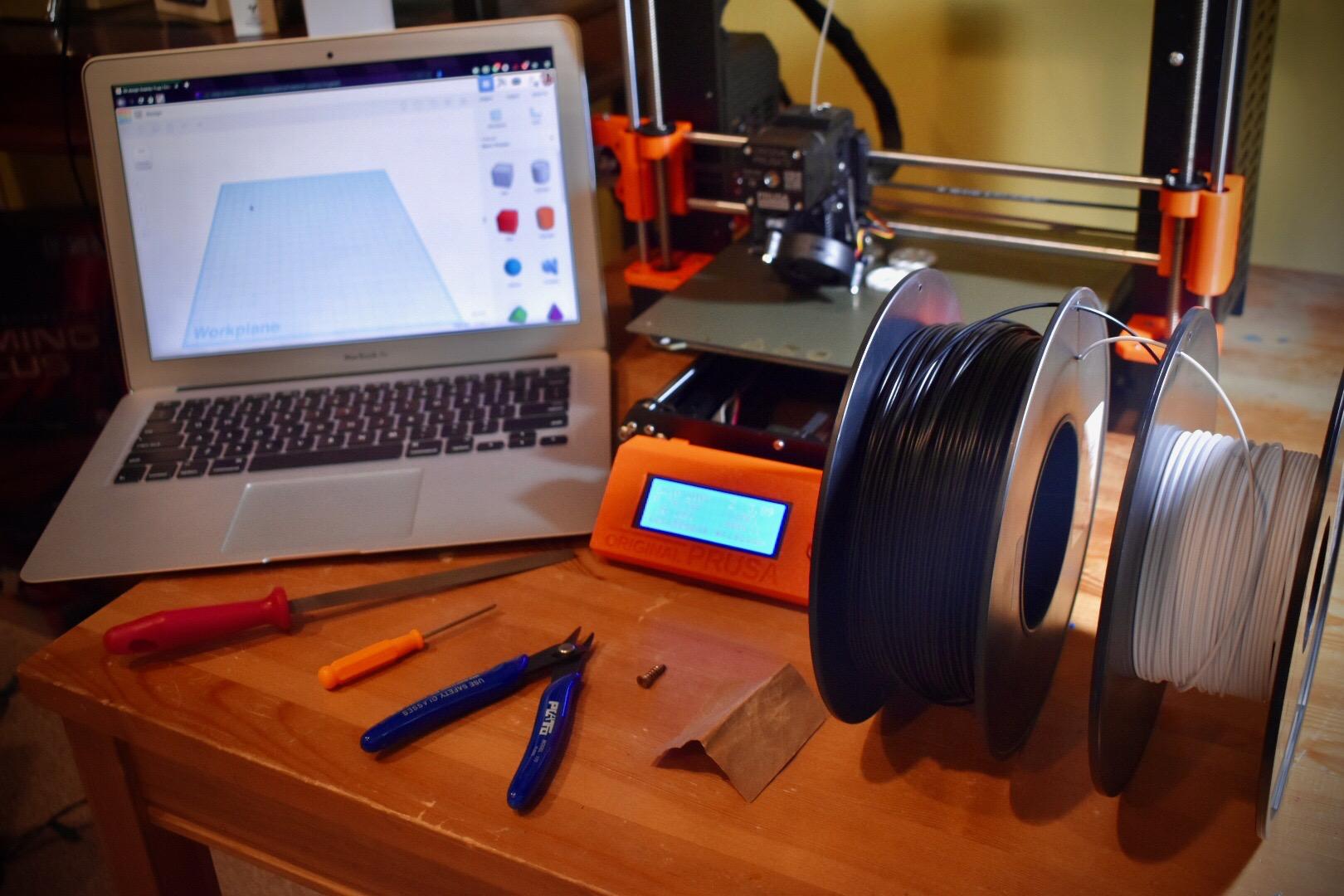
Supplies
To complete this project, you will need a computer, Tinkercad account, Cura slicing software, 3D printer, ABS or PLA filament, PETG or any strong filament, and rasps, files, or sandpaper. The PETG or strong filament is essential for the project to work. One of the pieces requires strength to function and without it, the entire puzzle will not work! For the rest of the pieces, ABS filament is optimal, but PLA is also usable (I do not have ABS, so I used PLA for mine). You will additionally need 6 different colors of any material filament and super glue or hot glue if you plan on printing the color caps, which give the final product a touch of color. Finally, you need 6 screws and 6 springs, which you can buy from https://www.thecubicle.com/collections/accessories for $0.99.
Understanding the Central Mechanism
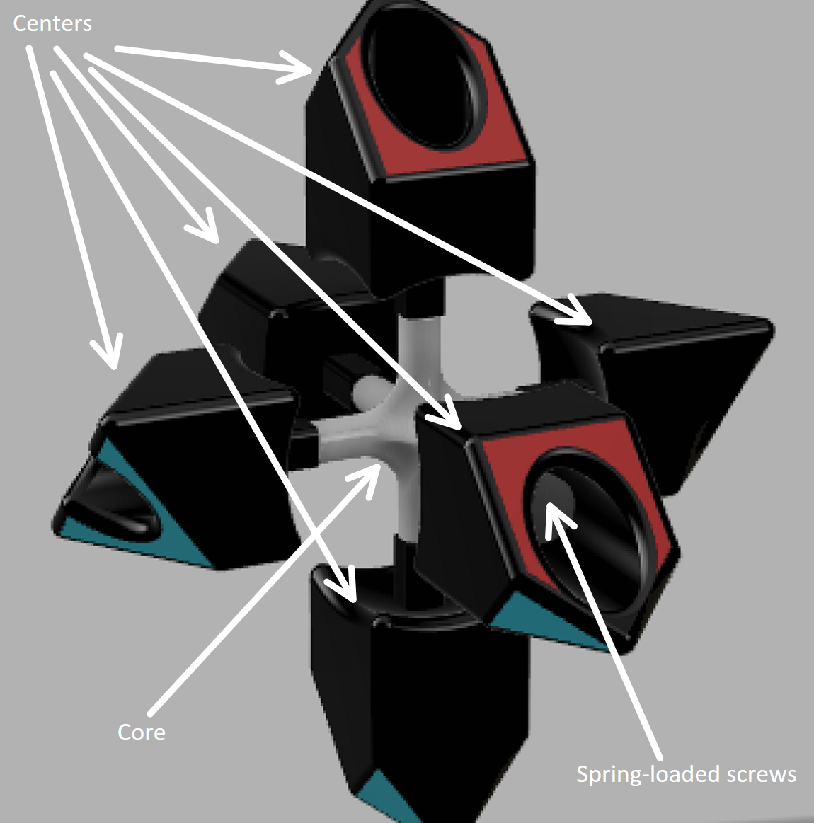
Before you dive into the design process (or if you are downloading the parts, this will be helpful for the assembly), it is crucial to understand how the mechanism works. In any sort of 3x3x3 Rubik's Cube, there are four different types of pieces. At the very center of object, concealed from the outside, is the core. This core consists of six protruding tubes that points to each face on a standard cube. The next type of piece is the centers. There six centers, which rotate, but never change in position. A screw and spring mechanism is utilized to allow the centers to be more flexible and adapt to the other pieces. The screws from the hardware set are tightly bound to the core while loosely passing through the center pieces. This allows the centers to rotate without losing connection to the core piece. A spring is loaded onto each screw to allow the center to stretch away from the core slightly, which accommodates for minor 3D printing errors.
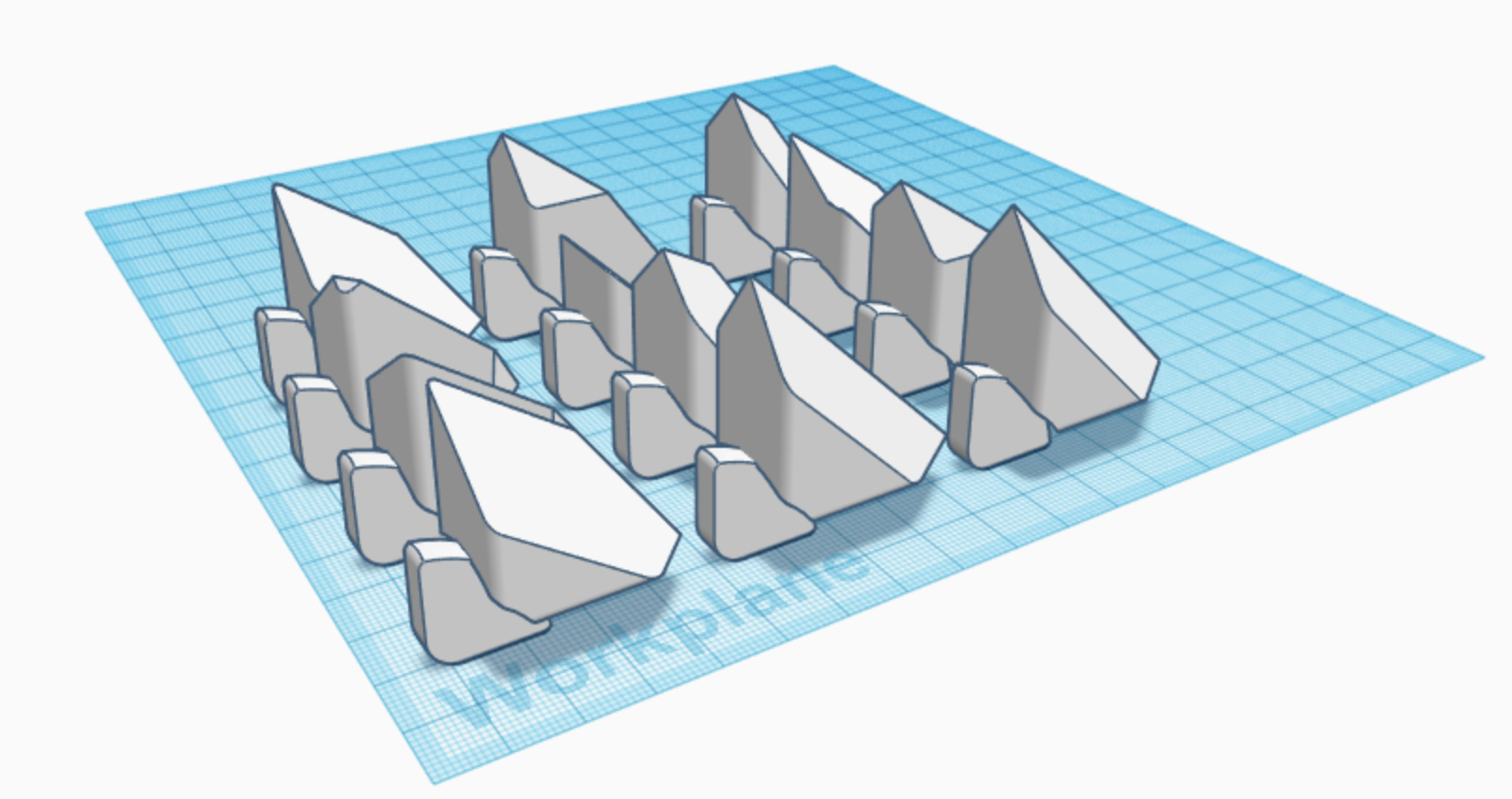
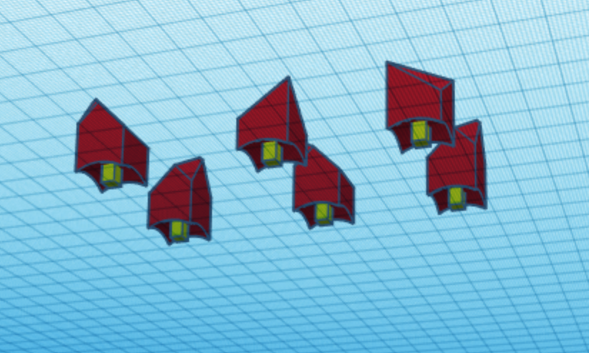
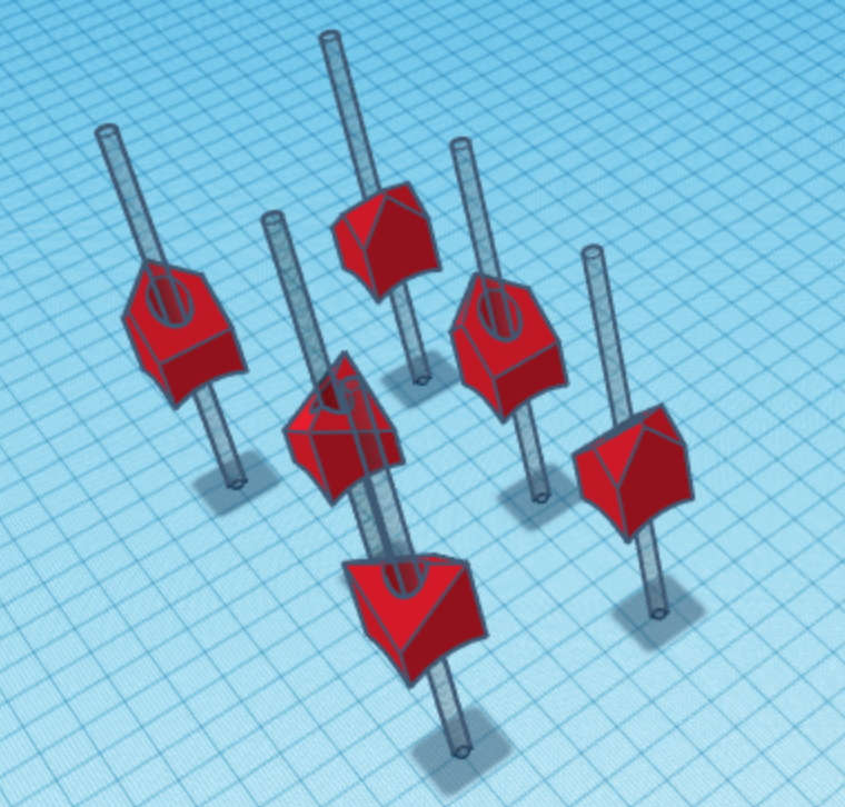
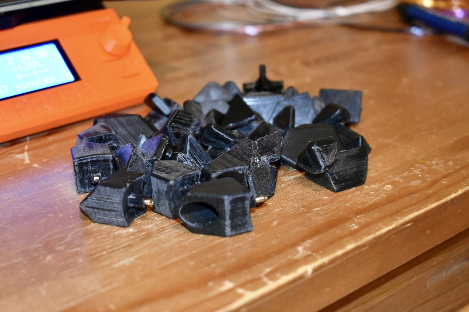
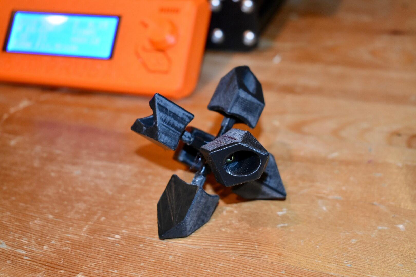
Understanding the Corners and Edges
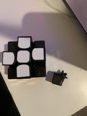
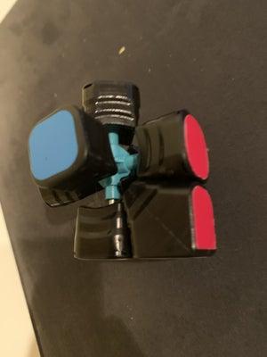
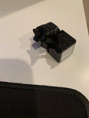
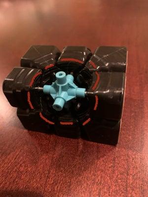
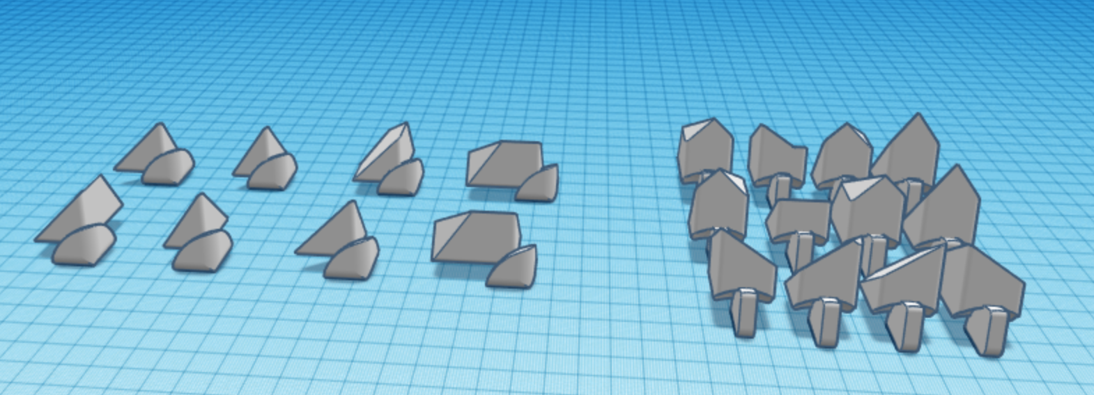
Above are pictures of a dismantled Rubik's Cube.
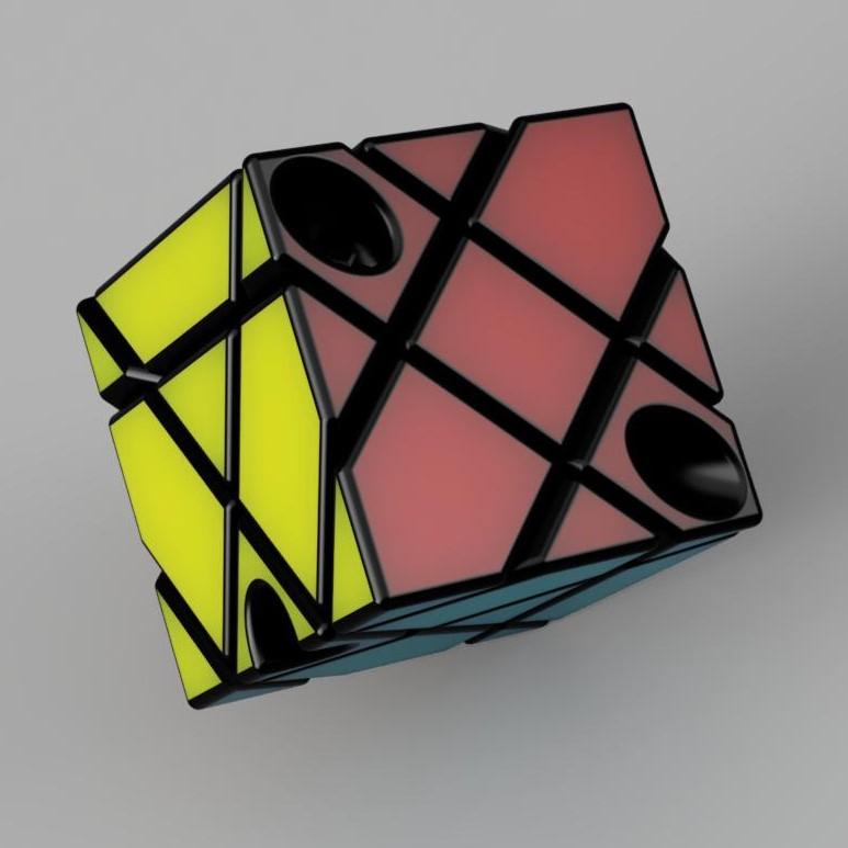
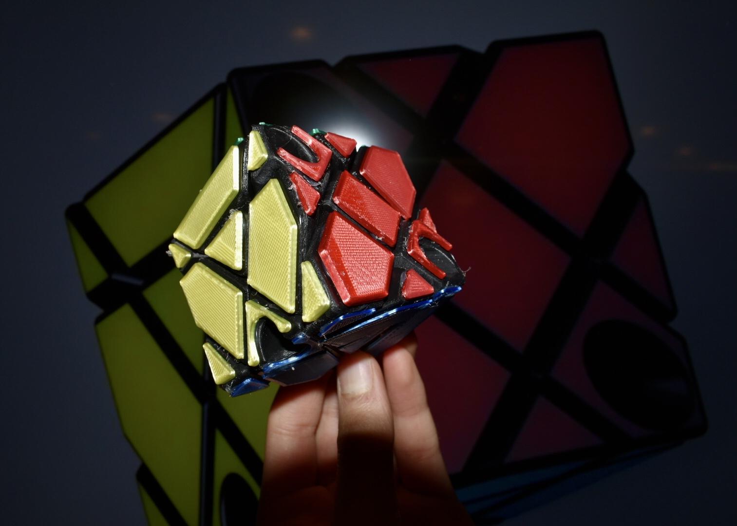
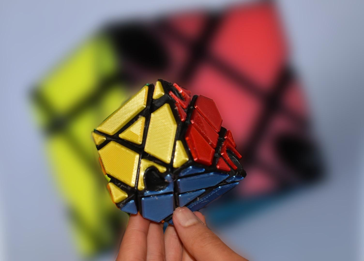
The last two types of pieces are edges and corners. There are twelve edge pieces and eight corner pieces. These pieces move throughout the cube around the centers. Each edge has a clip that fits into the center pieces. The spring mechanism causes the center pieces to put force onto these edge clips, creating friction and thus keeping the pieces together. This is shown in the first two pictures. Finally, the corner piece has a clip of its own that meshes with that of the edge piece, which causes the corner piece to be bound to the puzzle through a press-fit, as shown in the third picture. Although this intricate mesh explains how the puzzle remains assembled, there is still the crucial factor of turning. In a Rubik's Cube, the interior portion of the pieces, which rest on each other, form a sphere, called the Jaap's sphere. Since each clip, as referred to earlier, are portions of this common sphere, this puzzle can allow for turning on all three dimensions. The Jaap's sphere is shown in the last picture of a disassembled Rubik's Cube. This is a complicated concept to grasp, but going through the design process will help you understand it more. In this particular project, the axes that control the turning are not parallel to the sides of the cube, causing the puzzle to jumble into a mix of both shape and color. Watch the end of the overview video from the introduction to see this shape-shifting in action!
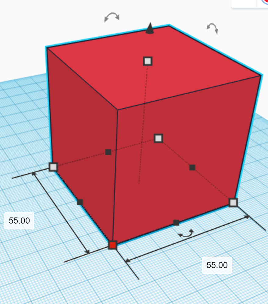
The External and Internal Total Shapes

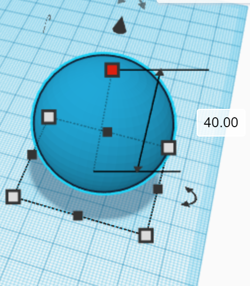
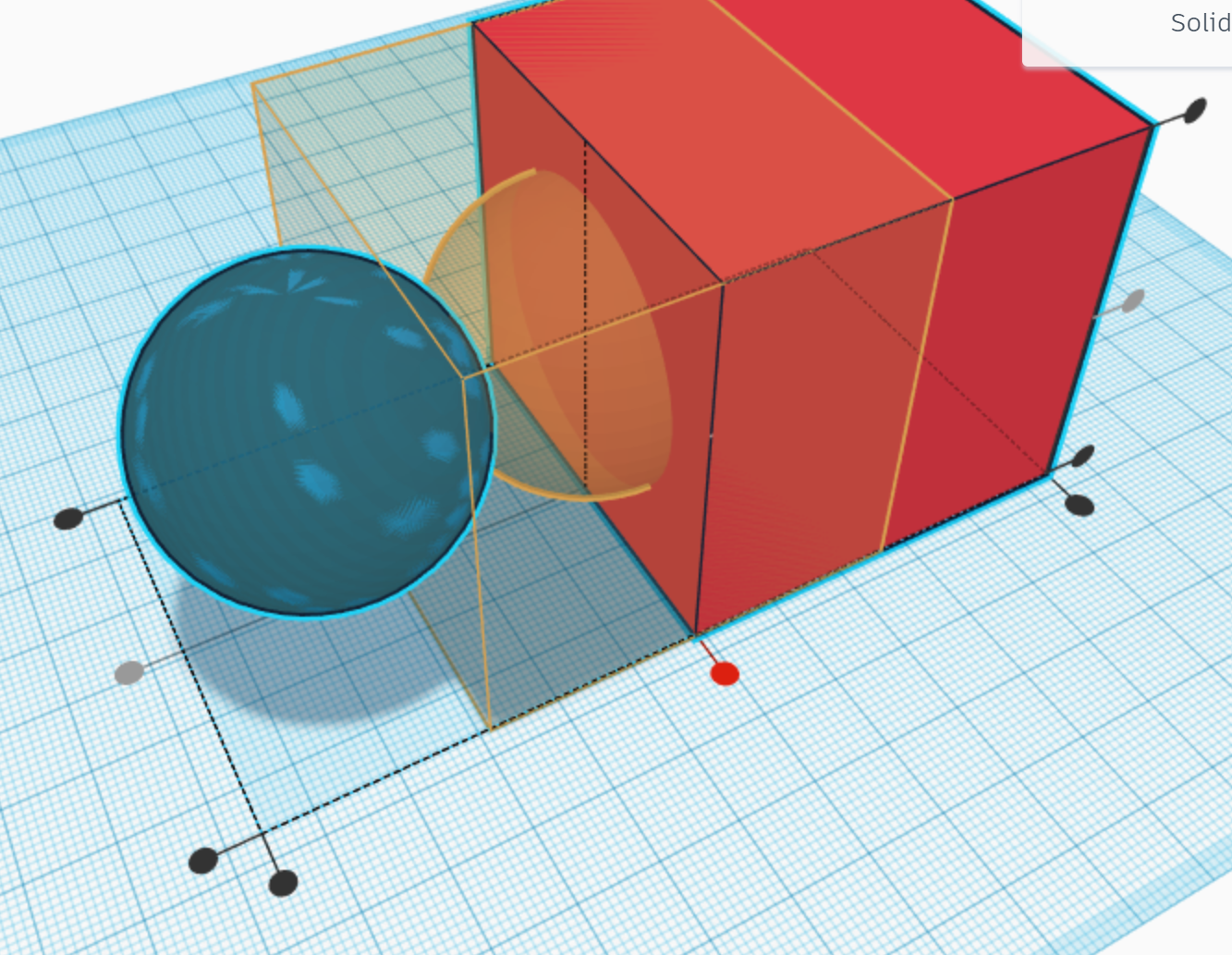
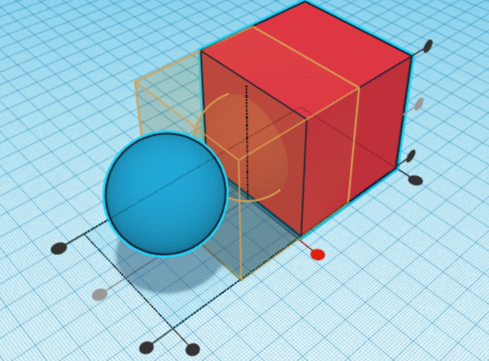
In this guide, follow each picture in order. This will allow you to understand the parts of each step visually. To start the design process, create a new project in Tinkercad. Then, add a box to your design. Change its dimensions to 55 mm by 55 mm by 55 mm. Next, add a sphere to your design and change the setting of 18 steps to 24 steps, which will theoretically make the puzzle function more smoothly. Change its dimensions to 40 mm by 40 mm by 40 mm. Duplicate the shape by selecting it and clicking command D on a Mac or control D on a Windows PC and convert the new one to a hole. After that, select that hole and the cube by holding shift and clicking on each. Finally, center align those three shapes using the align tool.
Cutting Out the Internal Edge Pieces
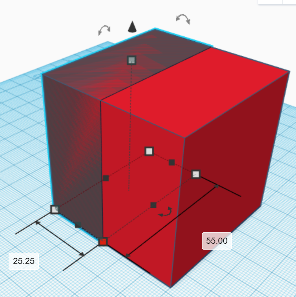
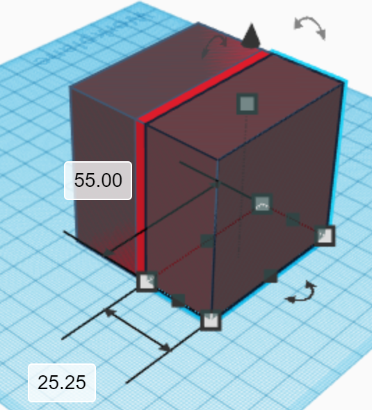
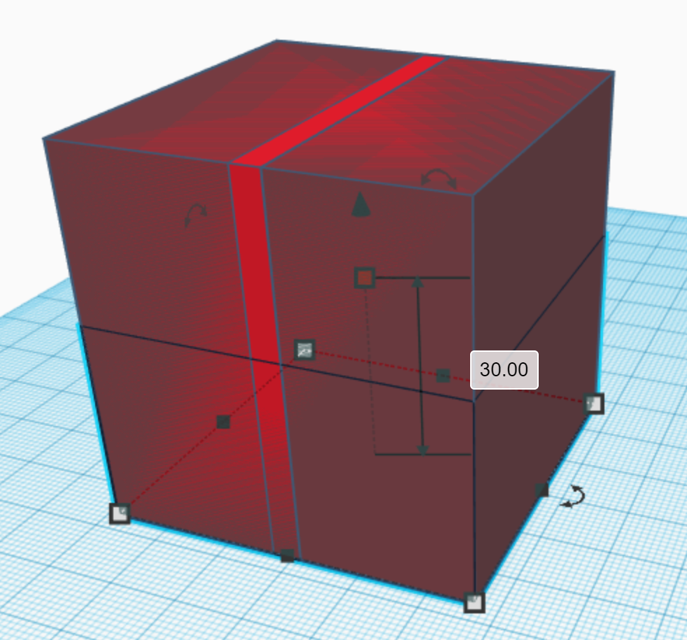
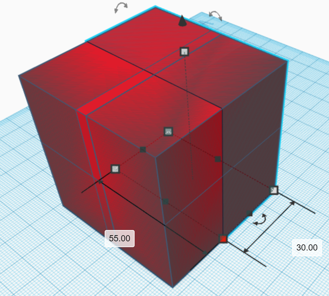
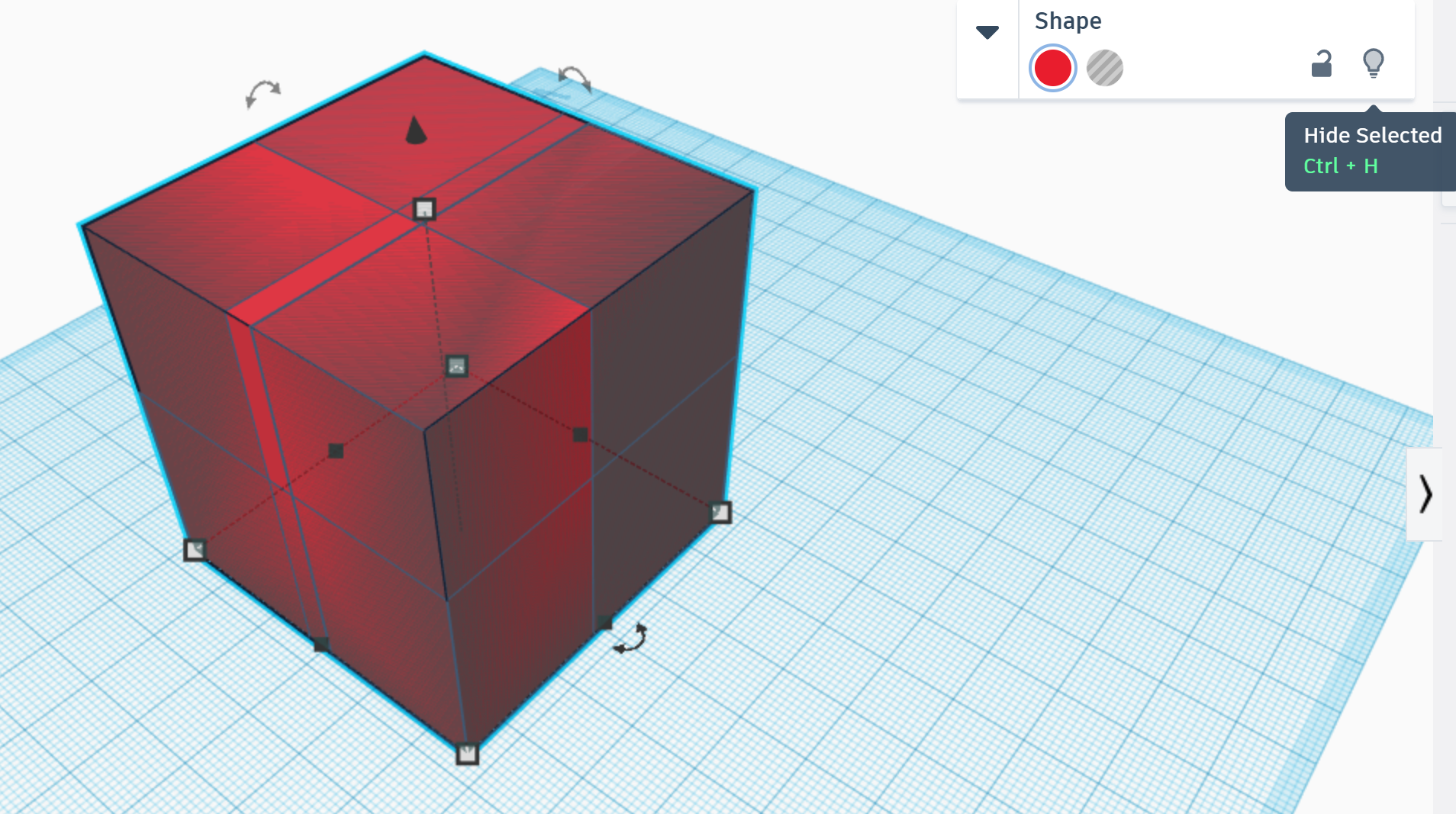
Select the box and duplicate it. Select one of the corners of the new box and change one of the dimensions shown to 25.25 mm. Then, make this shape a hole. Repeat this for the opposite side as well. After that, repeat this using the bottom of the cube shape, but change the dimension to 30 mm instead of 25.25 mm. Next, repeat in the back, again changing the dimension to 30 mm. Once you are done with that, select the red box by clicking on its visible sliver. After, click the light bulb icon to hide, but not delete it. Do the same with the sphere hole. Now, the only solid left should be a sphere. Lastly, group every showing shape in the design and you can show the other two shapes using show (light bulb) tool.
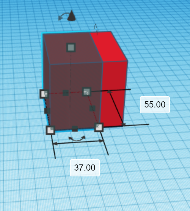
The Basis for Cutting Out the External Edge Pieces
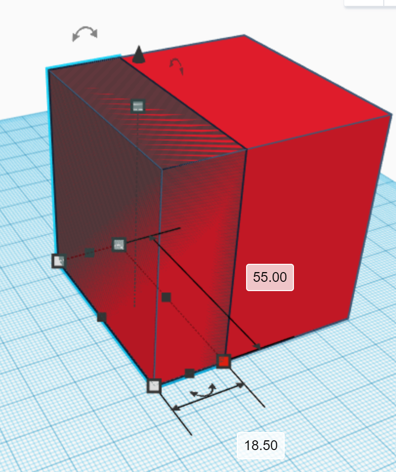
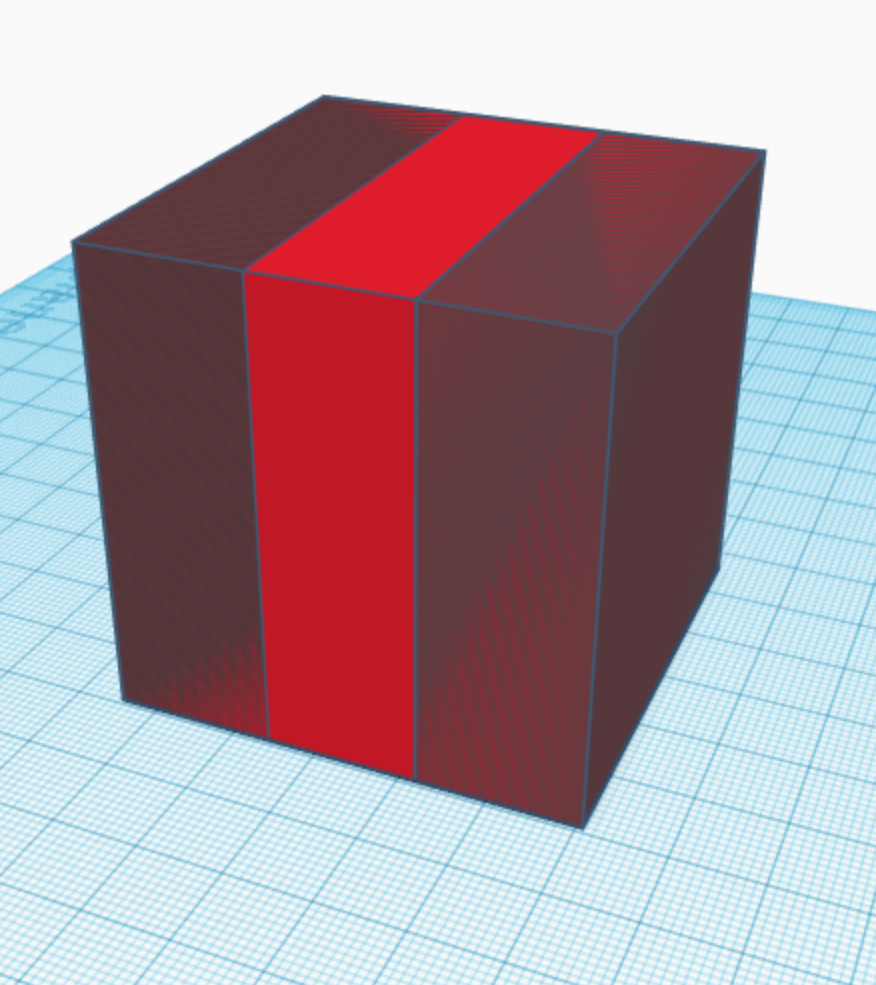
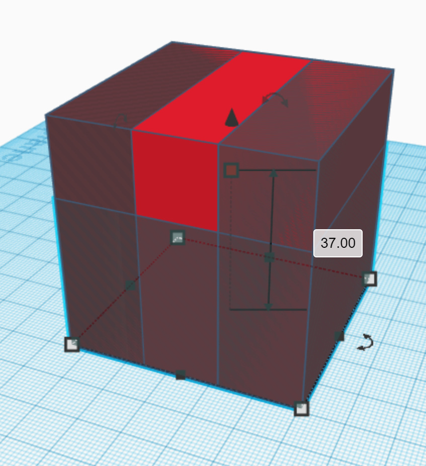
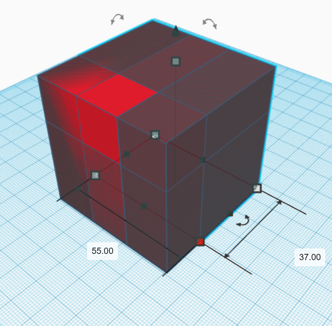
This step is similar to the last step except that the dimensions are different. Select the box and duplicate it. Select one of the corners of the new box and change one of the dimensions shown to 18.5 mm. Then, make this shape a hole. Repeat this for the opposite side as well. After that, repeat this using the bottom of the cube shape, but change the dimension to 37 mm instead of 18.5 mm. Finally, repeat in the back, again changing the dimension to 37 mm.
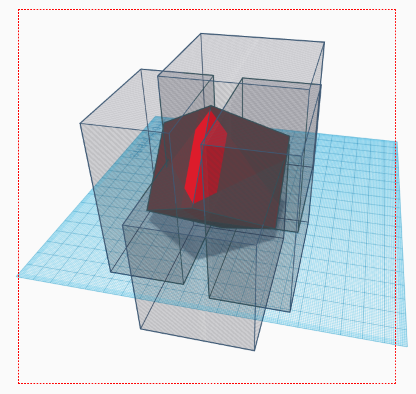
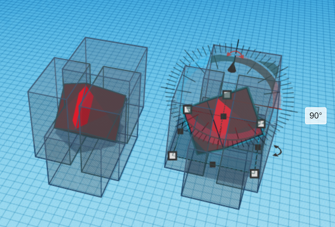
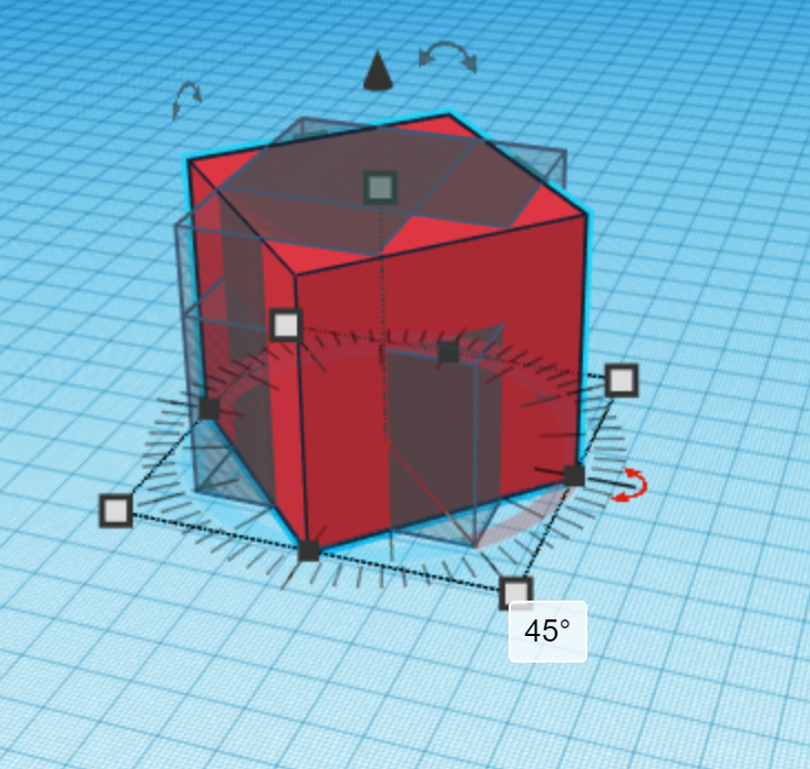
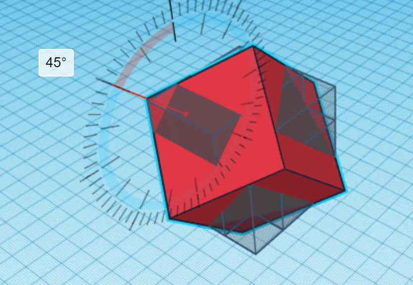
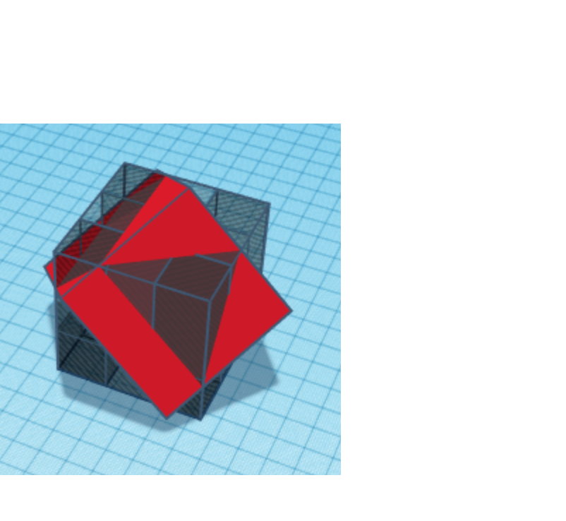
Rotating the External Box and Adapting the Edge Cut-Out Shapes
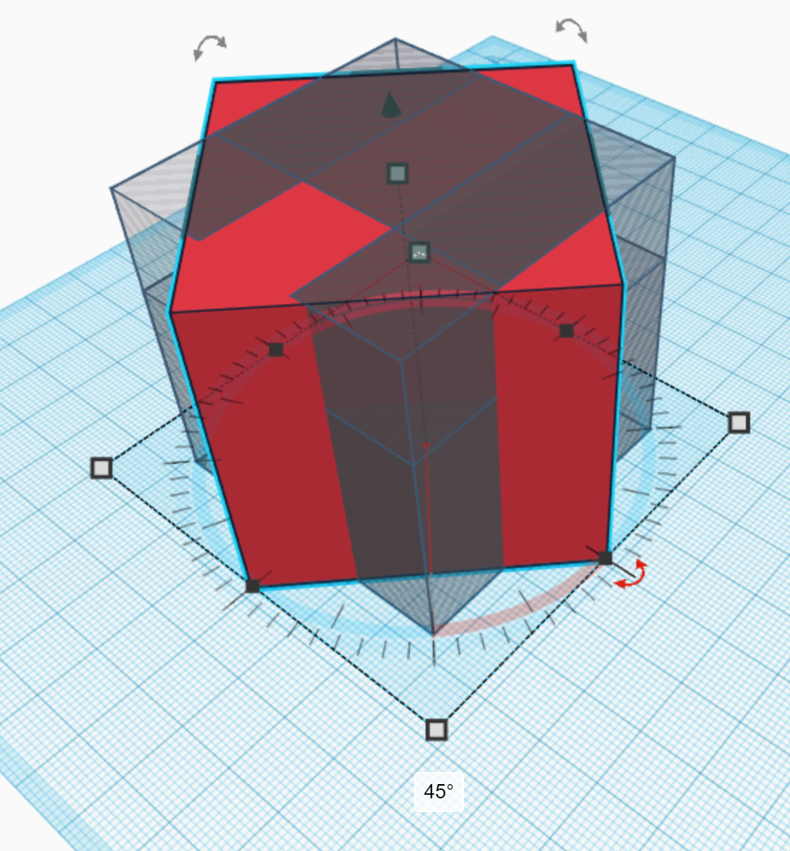
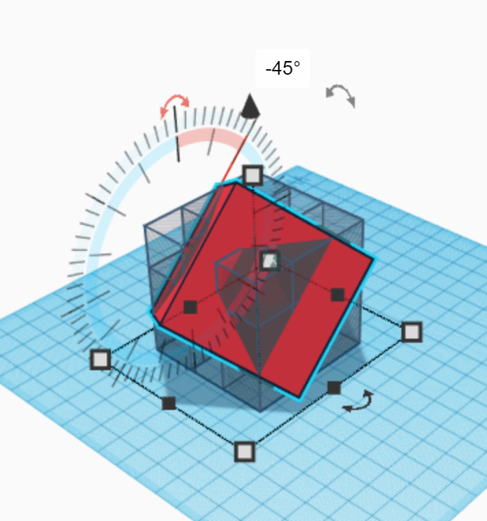
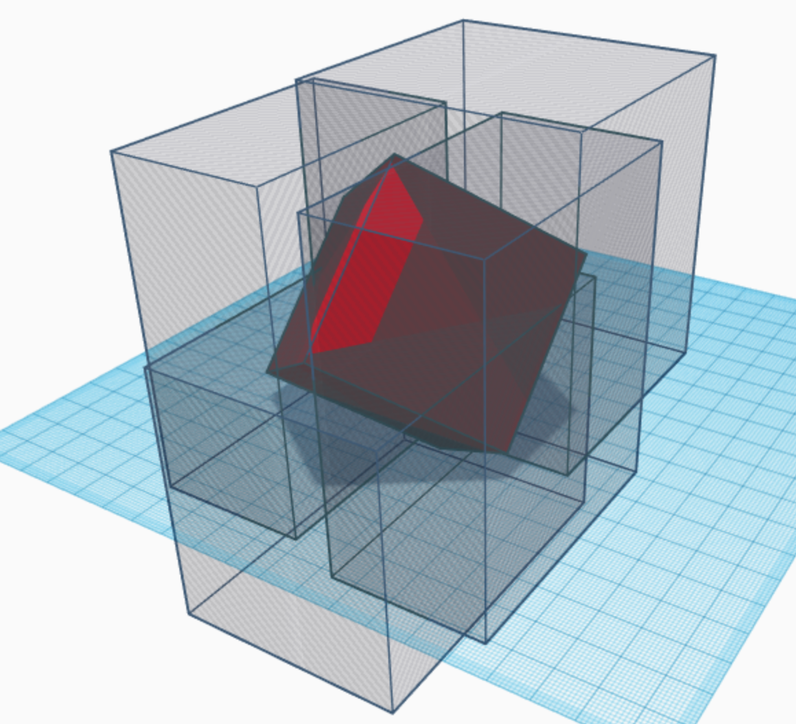
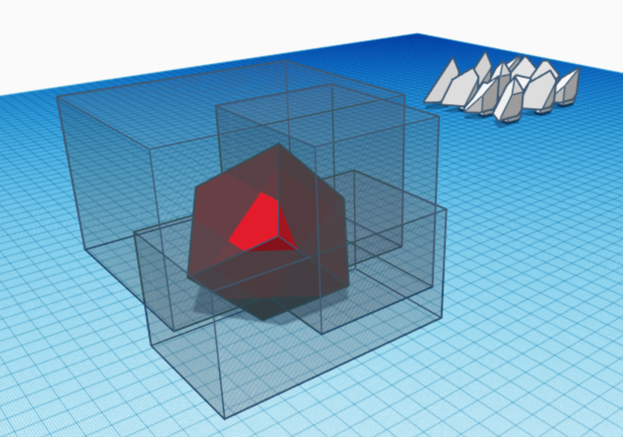
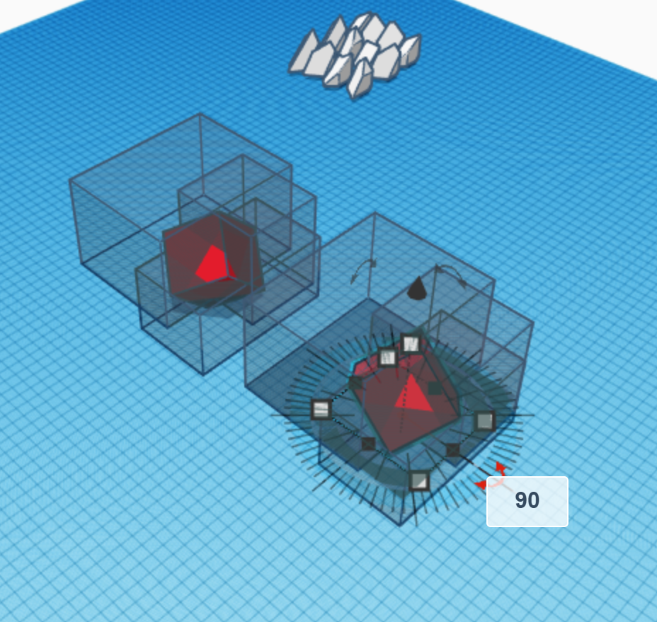
Start by rotating the box by 45 degrees on the plane and then rotating it vertically by 45 degrees again. Keep in mind that these rotations are purely aesthetic, so you can choose how much you rotate it on each axis. After rotating the box, the cutting bodies will no longer go through the entire shape, so you will need to extend their dimensions. Change the logical dimension of each of the cutting bodies so that it goes through the rotated box. Make sure not to fiddle with the boundaries that could change the result when they are grouped with the rotated cube (look at the third picture for reference).
Forming the Edge Pieces
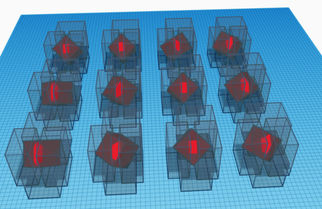
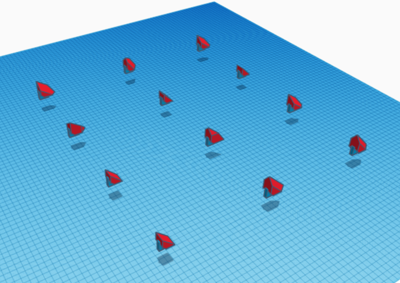
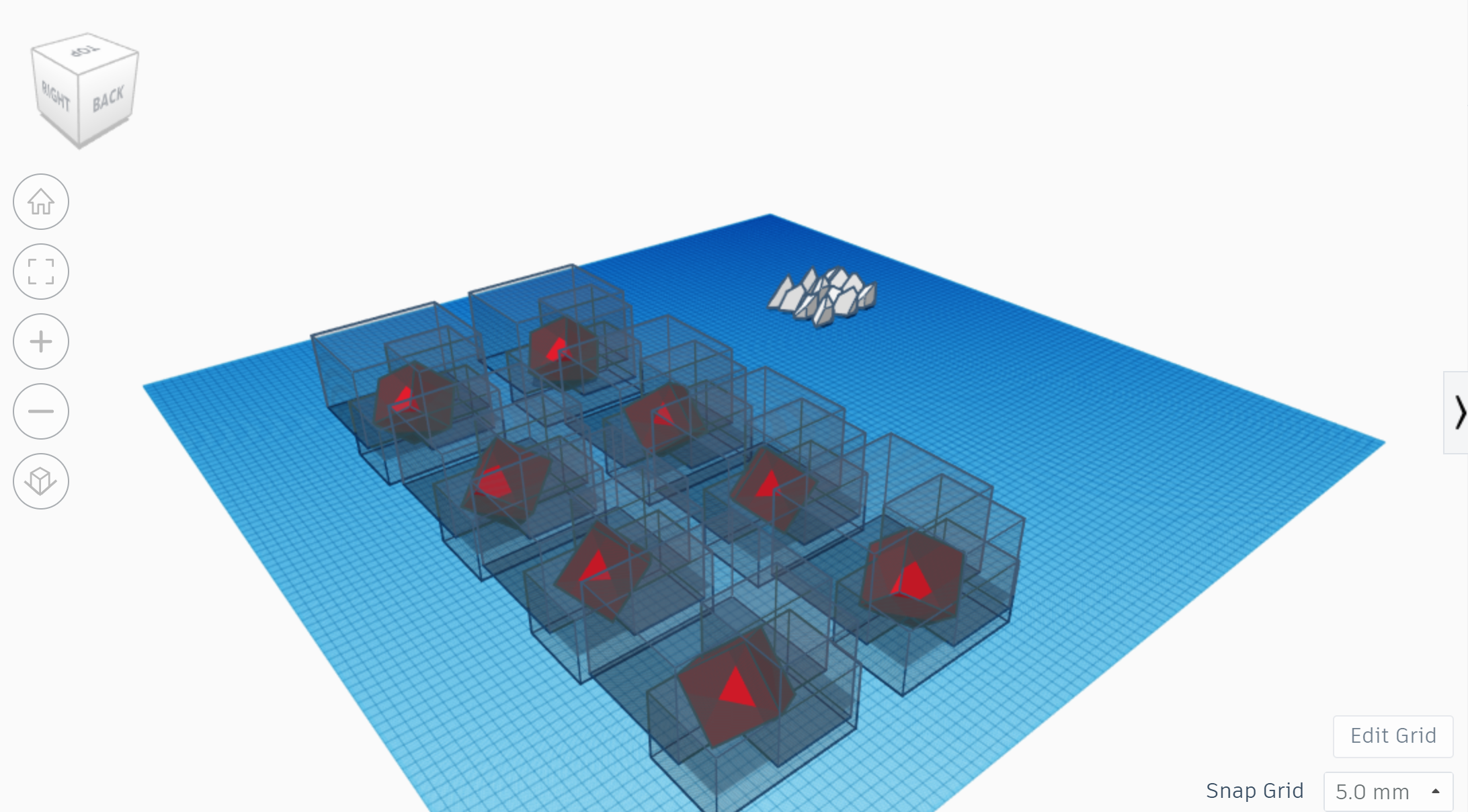
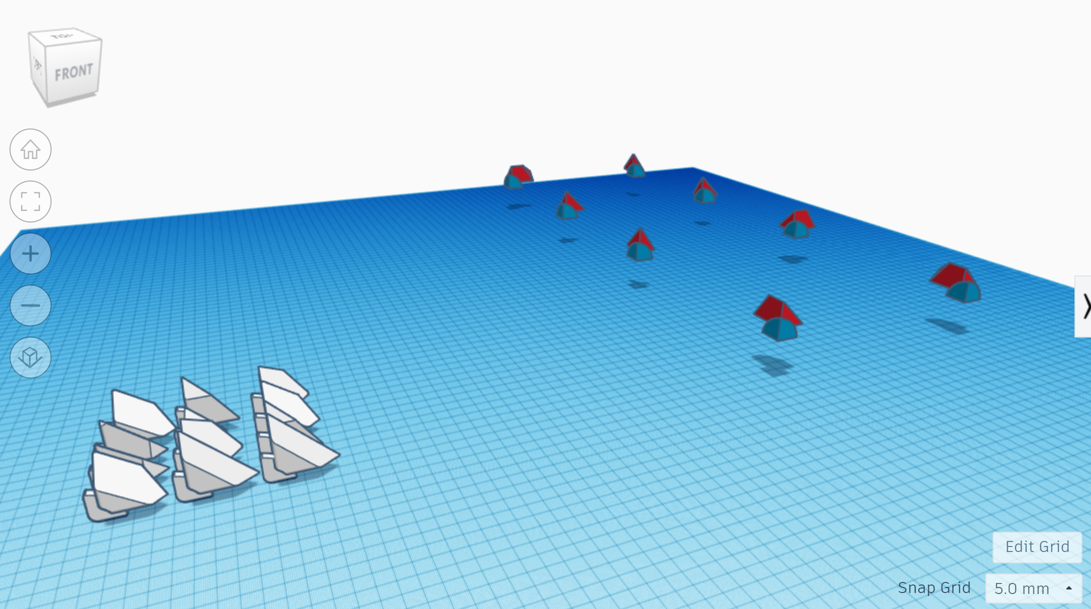
Select everything in the design, duplicate it, and move the new set of shapes away. Rotate the cube by 90 degrees in any direction. There are 12 edge pieces on any 3x3x3 Rubik's Cube Puzzle. Repeat this step, duplicating the set of shapes and rotating the cube by 90 degrees or sometimes 180 degrees until each of the 12 possible distinct orientations are produced. To do this systematically, consider that because 360/90 = 4, there are 4 different ways to rotate the cube per dimension. Since there are 3 dimensions and 3x4 = 12, there are 12 different orientations; do one dimension at a time to make this process logical rather than random. You can even arrange them on the work plane to indicate which possibilities you already covered. Finally, group each of the twelve sets of shapes individually excluding the internal solid that is a portion of a sphere (or you might need to group each set along the way because Tinkercad could crash with too many shapes). This is by far the most complicated step, so you great job if you've made it this far!
Edge Piece "Metafillets"
Go to the tab on the right side of your design that has all of the shapes. Find "shape generators", then go to "all", and click on page 12. Then, drag the shape called "metafillet" onto the workplane. Make its dimensions 5 mm by 5 mm horizontally and a dimension vertically that is at least about 10 mm. Convert this shape to a hole and rotate it 90 degrees on two axes so that can be aligned at the corner of the internal portion of one of your edge pieces (see first picture). Then align it so that it so that it is positioned according to the second picture. Do this for each piece. The following part in brackets is optional. [Apply this concept to the positions shown in the fourth picture. Make sure that for these metafillets, the dimensions are 1.5 mm by 1.5 mm. While most pieces of this puzzle are distinct, all of the edge pieces have certain parts in common, so the positions for metafillets in the third picture are applicable to all of them.] Finally, group the fillets you have created to their corresponding parts. The edge pieces are done! Now, you can now organize them on the workplane if you want to.
Starting the Corners

Put the edges aside for now. Add a box to your design. Change its dimensions to 55 mm by 55 mm by 55 mm and then a sphere, making sure to change the setting of 18 steps to 24 steps. Change its dimensions to 40 mm by 40 mm by 40 mm. After that, select the sphere and the cube and center align them on all three axes. (Sound familiar? This step is almost the exact same as the first step.)
Cutting Out the Internal Corner Pieces
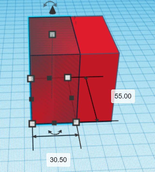
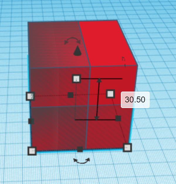
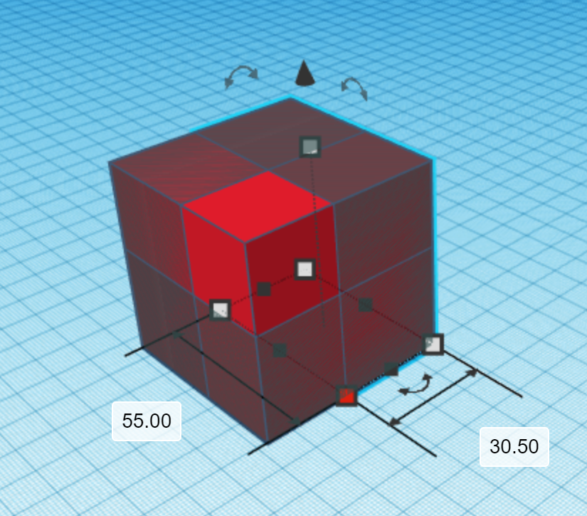
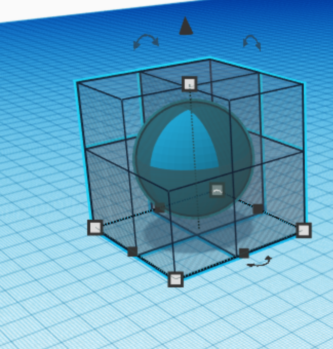
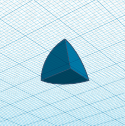
Select the box and duplicate it. Select one of the corners of the new box and change one of the dimensions shown to 30.5 mm. Then, make this shape a hole. Repeat this for two other sides so that it matches the pictures. Once you are done with that, select the red box. Then click the light bulb icon to hide, but not delete it. Now, the only solid left should be a sphere. Lastly, group every showing shape in the design and show the box using show tool.
The Basis for Cutting Out the External Corners
Next, select the box and duplicate it again. Select one of the corners of the new box and change one of the dimensions shown to 37 mm and make it a hole. Repeat this for two other sides so that it matches the pictures (just like the previous step except with different dimensions). Do not group these shapes this time.
Rotating the External Box and Adapting the Corner Cut-Out SHapes
Rotate the box just like you did in step 6. After rotating the box, the cutting bodies will no longer go through the entire shape, so you will need to extend their dimensions. Change the logical dimension of each of the cutting bodies so that it goes through the rotated box. Make sure not to fiddle with the boundaries that could change the result when they are grouped with the rotated cube.
Forming the Corner Pieces
This step is very similar to step 7. Select the shapes you created in Steps 9 - 12 and duplicate them. Move the new set of shapes away. Rotate the cube by 90 degrees in any direction. There are eight corner pieces on any 3x3x3 Rubik's Cube Puzzle. Repeat this step, duplicating the set of shapes and rotating the cube by 90 degrees or sometimes 180 degrees until each of these eight possible distinct orientations is produced. To do this systematically just like in step 7, arrange them on the work plane to indicate which possibilities you already covered. Finally, group each of the eight sets of shapes individually excluding the internal solid that is a portion of a sphere (again, you might need to group each set along the way because Tinkercad could crash with too many shapes).
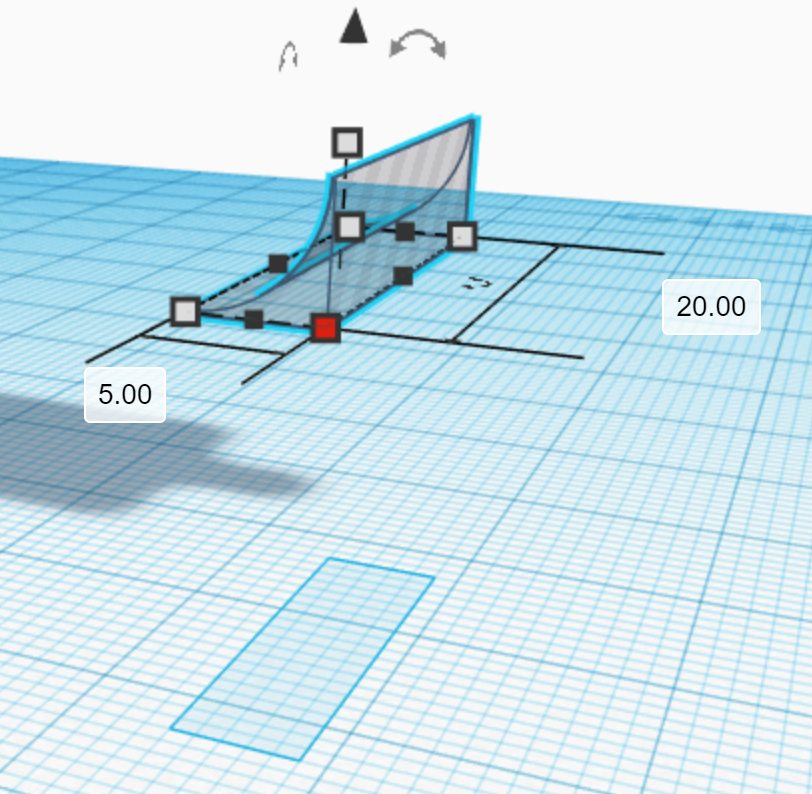
Corner Piece "Metafillets"
Similar to step 8, find the metafillets on page 12 of shape generators. Then, drag one onto the workplane and make it a hole. Set its dimensions are 5 mm by 5 mm horizontally and a dimension vertically that is at least about 20 mm. Duplicate this shape twice so that there are three. Then align each one so that they match the second picture. Do this for each piece. The following part in brackets is optional. [Apply this concept to the positions shown in the third picture. Make sure that for these metafillets, the dimensions are 1.5 mm by 1.5 mm. While most pieces of this puzzle are distinct, all of the corner pieces have certain parts in common, so the positions for metafillets in the third picture should be applicable to all of them.] Finally, group the fillets to their corresponding parts. If you did the optional part, make sure to to group those fillets with the red shape first and then group the rest. The corner pieces are done! Organize them on the workplane.
Starting the Center Pieces
Put everything you have done so far aside for now. Add a box to your design. Change its dimensions to 55 mm by 55 mm by 55 mm and then a sphere, making sure to change the setting of 18 steps to 24 steps. Change its dimensions to 40 mm by 40 mm by 40 mm and make it a hole. After that, select the sphere and the cube and center align them on all three axes. Finally, group the two shapes. (This step is similar to step 9 and step 1.)
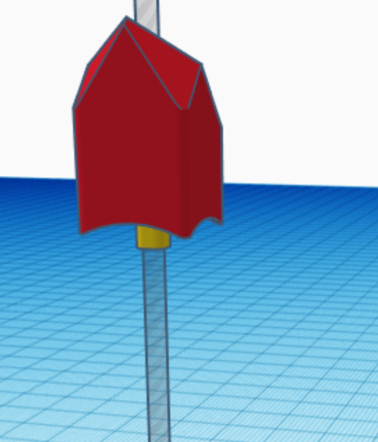
Creating the Internal Center Piece
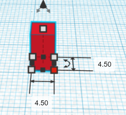
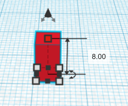
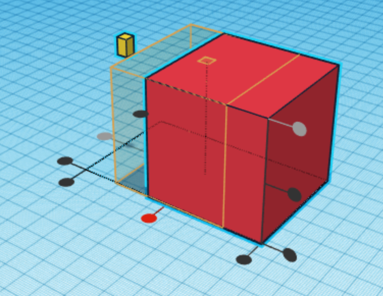
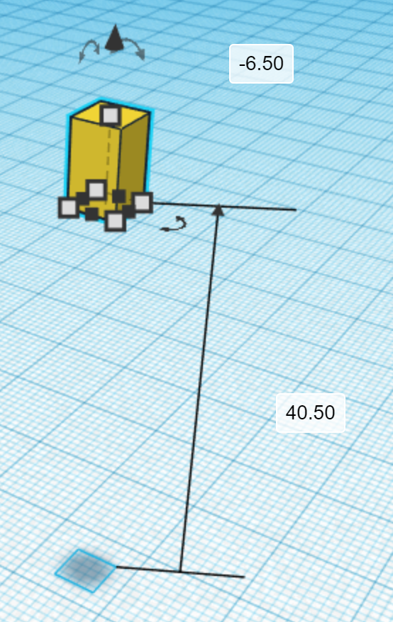
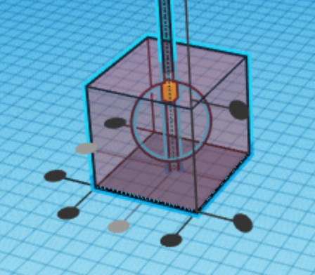
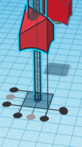
Create a box that is 4.5 mm by 4.5 mm by 8 mm. Then, center align it with the bigger box from the last step so that it is aligned to the top of it, but is center aligned horizontally, as shown in the third picture. Hide the larger box and then move the new one down by 6.5 mm. Finally, create a cylinder as a hole and make it 120 mm tall and 3 mm in diameter. Show the hidden box to horizontally, but not vertically, center align the three shapes. Finally, hide the larger box again to group the two showing shapes created in this step. (Then, you can show the shape again.)
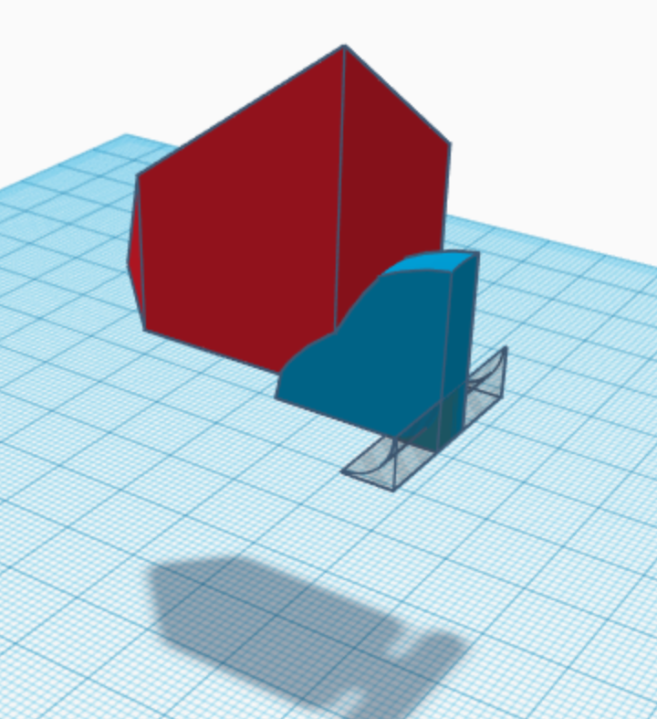
The Basis for Cutting Out the External Centers
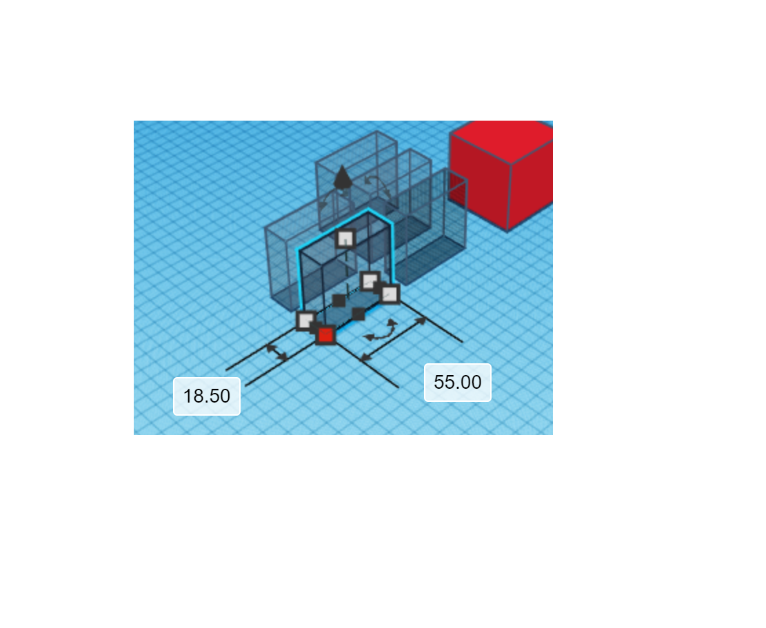
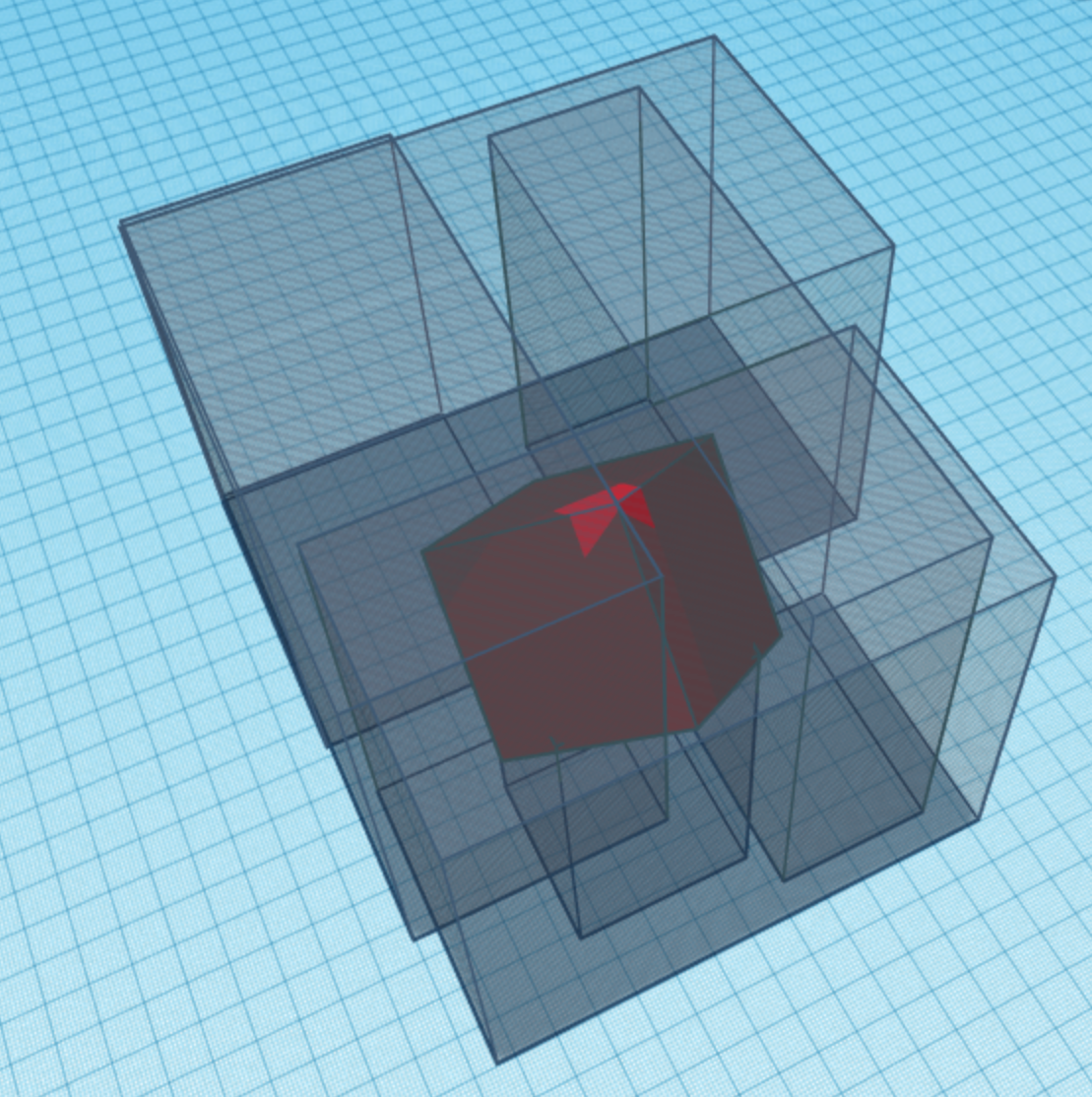
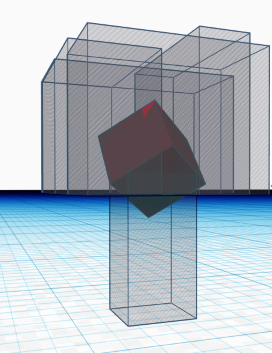
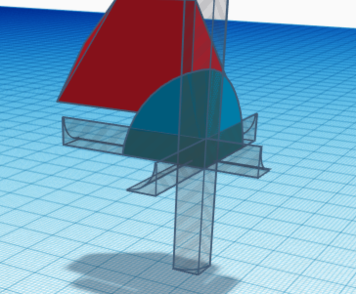
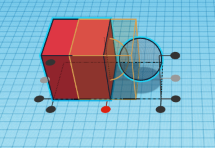
Create five boxes as holes that are each 55 mm by 55 mm by 18 mm. Then, use the rotation and alignment tool to position them according to the second picture. In doing so, make sure to not disturb the position of the large red box from Step 15. Rotate the largest box the same way you did in steps 6 and 12. Adapt the cutting shapes similarly to the way you did in those steps so that they serve their purpose (see the pictures).
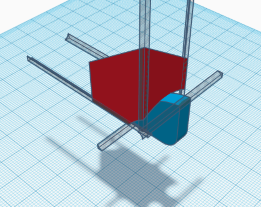
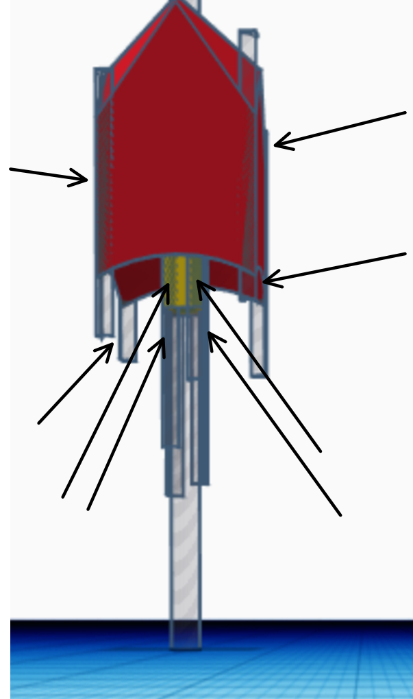
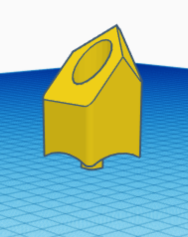
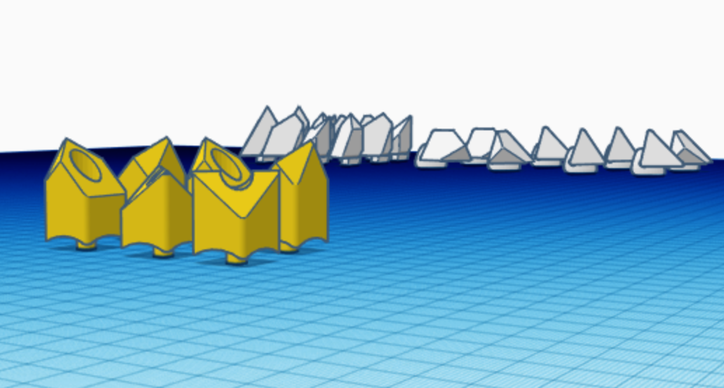
Forming the Center Pieces
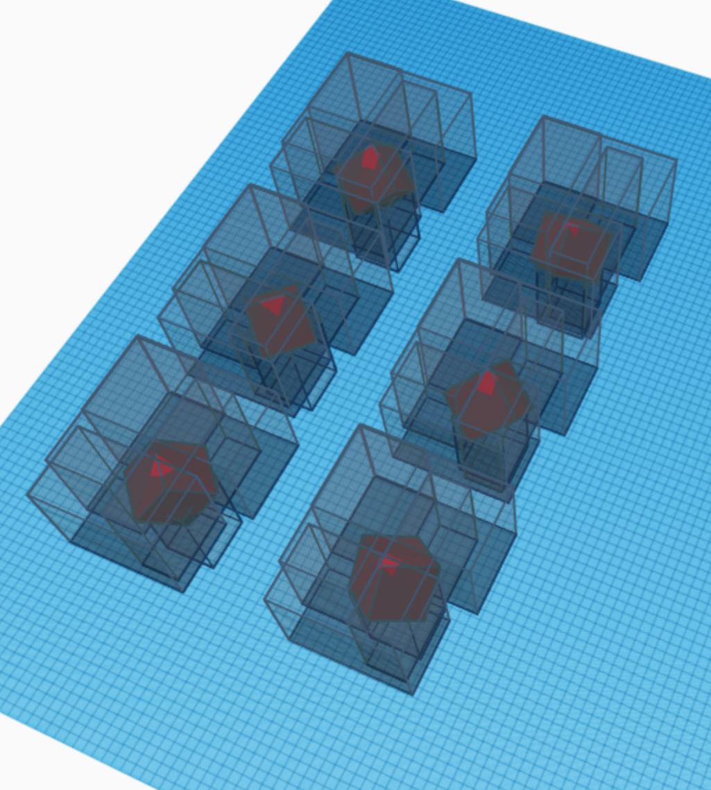
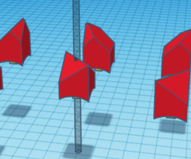
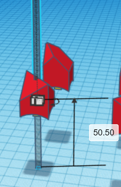
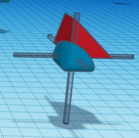
Just like in step 11 and 13, duplicate the shapes you created and rotate the larger box 90 degrees or 180 degrees to make all combinations. This time, there are six combinations. Group sets of shapes together excluding the smaller internal box created in step 16. Then, ungroup the each smaller box (yellow in the picture), which should make the cylinder visible. Duplicate the cylinder and move the new one upwards by 50.5 mm. Then, change it horizontal dimensions to 10 mm by 10 mm. Center align horizontally these four shapes and group the new, with cylinder with the shape that is red in the picture. Finally, do this for each center piece.
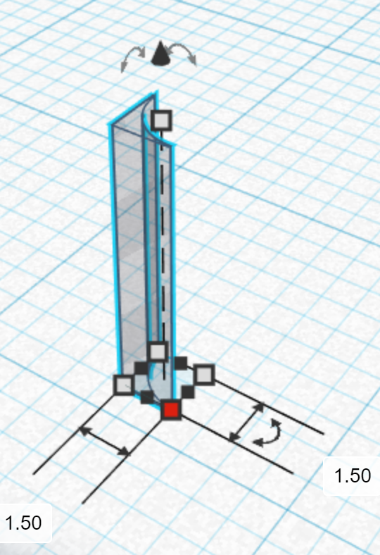
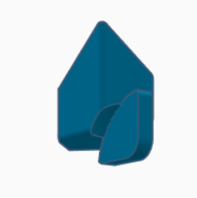
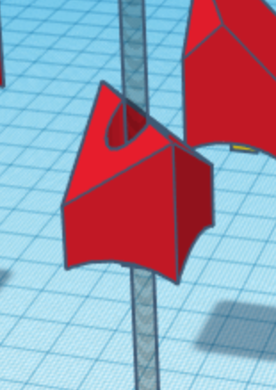
Center Piece "Metafillets" (Optional)
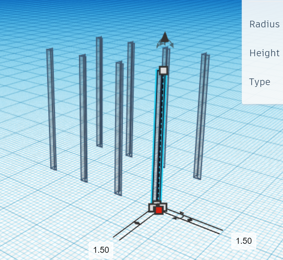
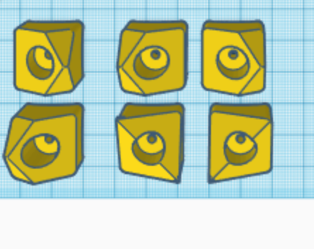
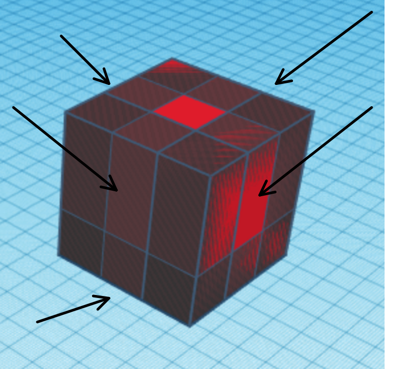
Drag out eight metafillets as holes and change their sizes to 1.5 mm by 1.5 mm by at least about 30 mm. Place them using the align and rotate tool so that they match the picture. Repeat this for each center piece. Group the internal yellow shape with its respective fillets and the external red shape with its corresponding ones to match the third picture. Next, group these three resulting shapes together and repeat this for each center piece. Finally, you can then organize them on the workplane. If you have made it this far, then the rest of the project should be a breeze for you; the most difficult steps are behind you!
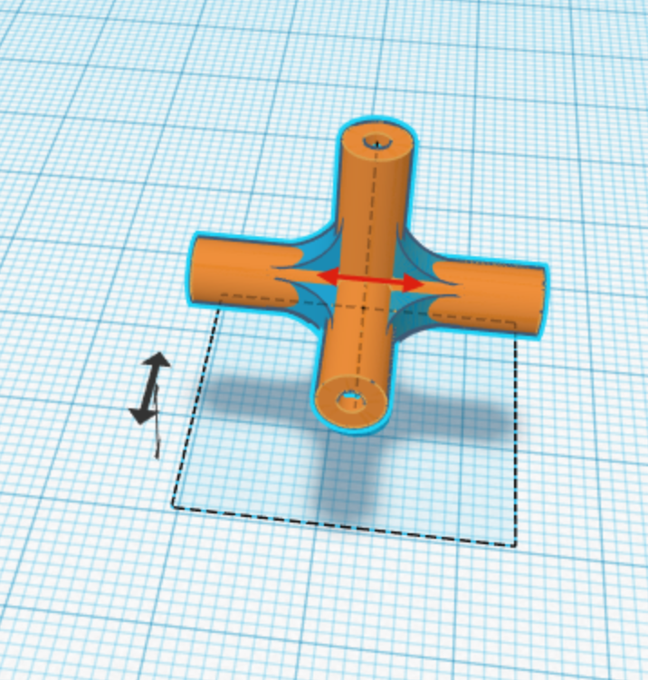
Forming the Core Piece
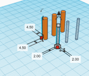

Put the other pieces aside for now. Create three cylinders that are 4.5 mm in diameter and 24.5 mm in height. Rotate each one by 90 degrees by different axes so that each one faces a different direction. Repeat that same process with three more cylinders that are 2 mm in diameter and 24.5 mm in height. Make these new cylinders holes rather than solids. Center align the six shapes you just created and group them.
Core Piece "Metafillets"
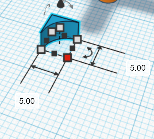
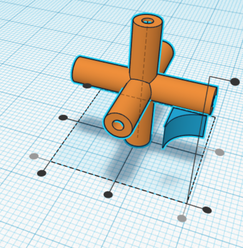
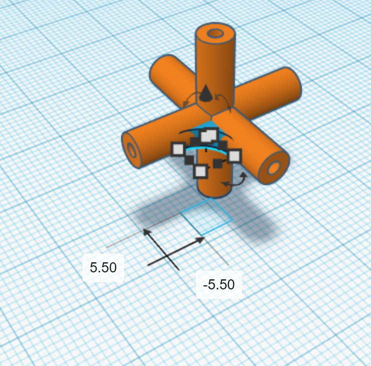
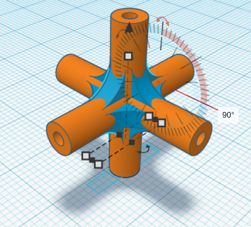
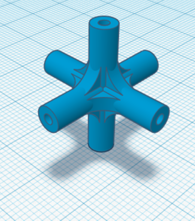
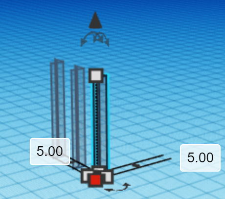
Create a metafillet and make it 5 mm by 5 mm horizontally and 2.5 mm vertically. Center align the fillet vertically with the shape you created last step and align it to the corner horizontally. Next, move the metafillet horizontally towards the core piece by 5.5 mm on both dimensions. Then, duplicate the metafillet and select one of them and the core piece. Rotate these shapes by 90 degrees. Repeat that process three times until it matches the fourth picture. After that, select the orange shape and the four blue shapes and duplicate them. Then use the mirror tool to reflect. Once you have done that, select and duplicate four of the metafillets that are in-line with each other. Rotate these new metafillets by 90 degrees so that the remaining edges of the core piece become rounded. Finally, group everything for the core piece to finish the design!
Converting the Designs to Gcode
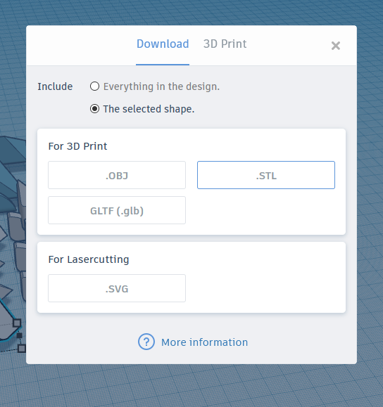
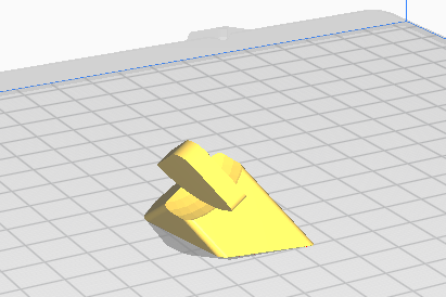
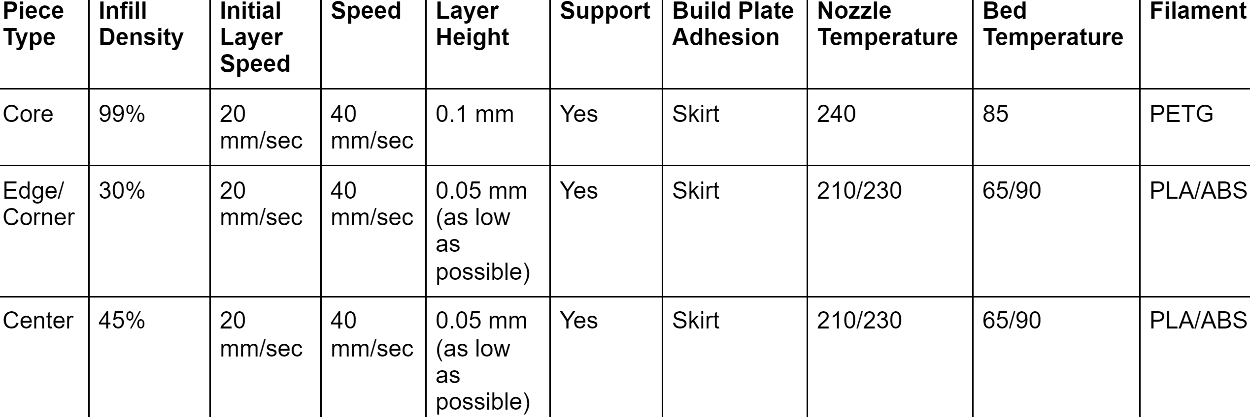
Choose one piece and click export or download it from the link at the beginning. Choose "the selected shape" and .STL. Open this file using your slicing software. The slicing software will turn your design into code that the 3D printer can understand and then fabricate. To specify how you want the machine to make each part, you can change the settings. These settings are dependent on which piece you are printing. View the chart above to see what slicer settings apply for each piece. These are my recommended guidelines; tweak them to be compatible with your printer. Make sure to position the piece you chose so that a larger side is its base. This will increase the probability of success for your print and decrease the amount of support material needed. For the best results, print each piece individually.
3D Printing and Post-Processing
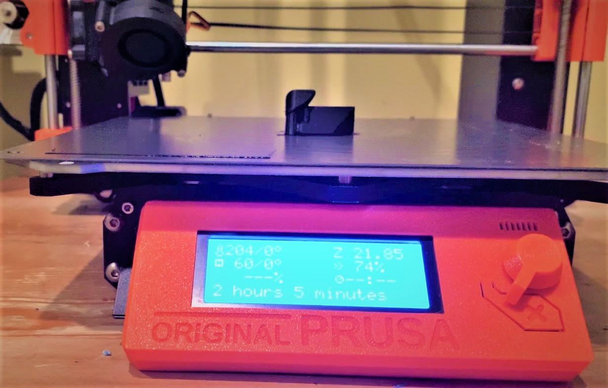
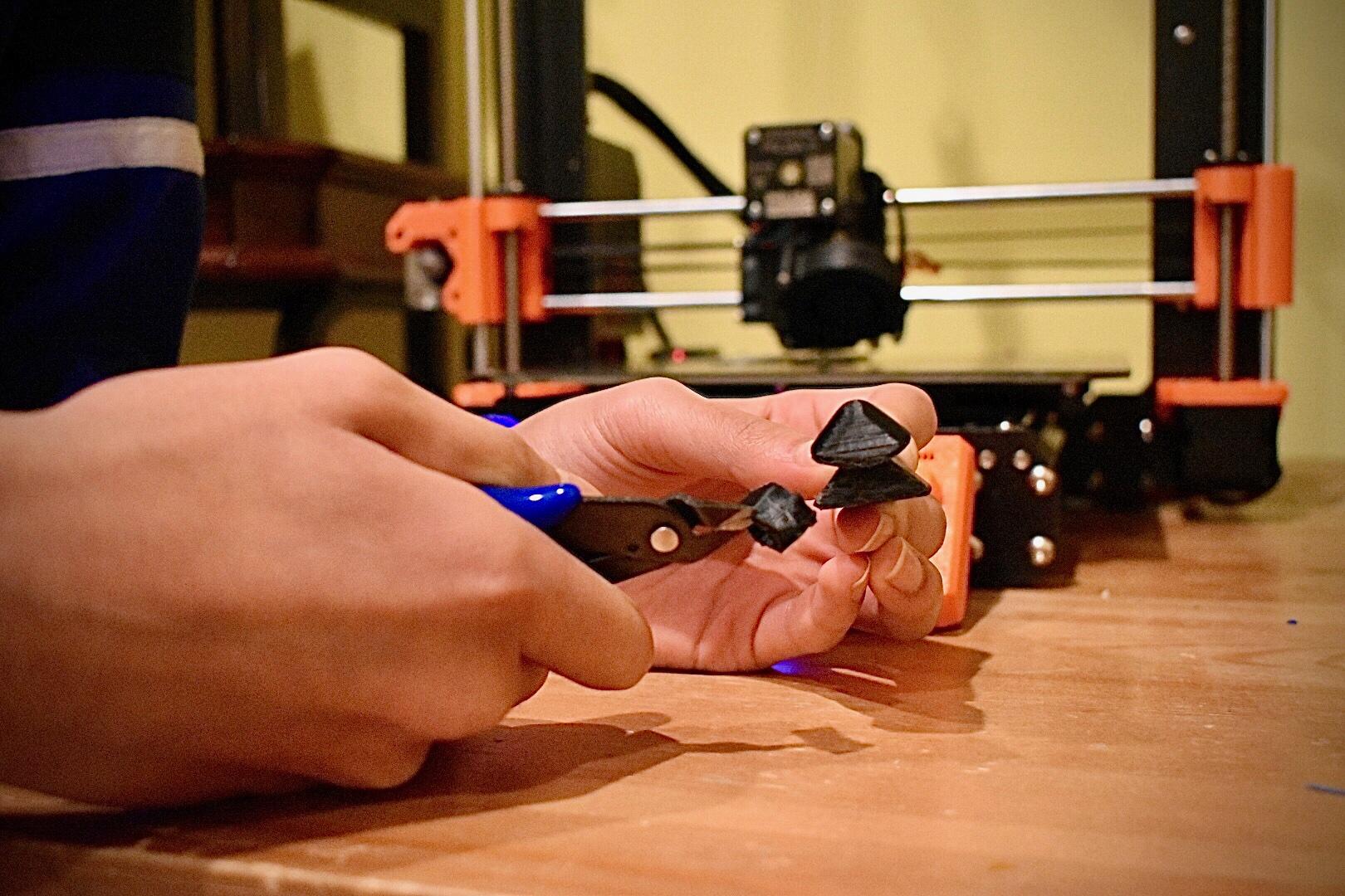
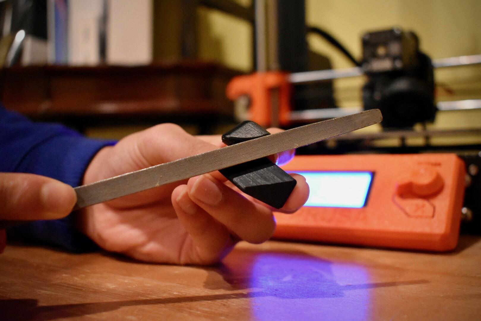
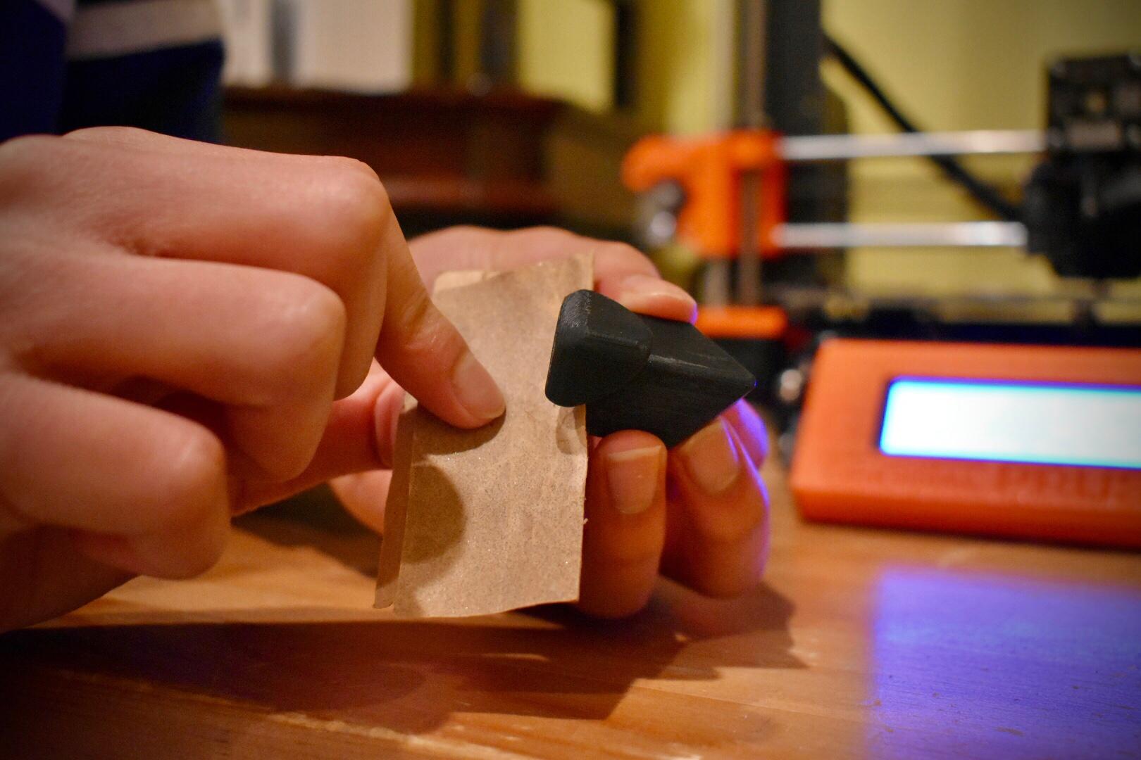
Give the gcode to your printer and let it print. Make sure to load the right filament according to the chart in the last step. When each piece is done printing, remove the supports using pliers and sand down rough surfaces using rasps or sandpaper. If you are using sandpaper, start with a rougher sheet and then move to one with a finer-grit.
Assembly and Finishing Touches
To assemble pieces, load each spring onto the screws. Then, insert each of them into a center piece and push it through. Push hard and screw the center pieces into each of the core's holes.
View the design above to comprehend which center goes where. Finally, start to put the edges and corners in their respective places, again following the design. Make sure the center is rotated the correct way when inserting the edges and corners in. The edges should easily clip between the centers and corners should snap into the edges. Assemble the entire puzzle in any way that works for you (i.e. by layer) except for one edge. Then, firmly wedge the last piece in. You are done! The more you turn the puzzle, the easier it will become to handle because the pieces will get used to each other. An optional aesthetic step you can also do is adding colors to the outside. If you printed your pieces in white, then you can use sharpies to add color to each side of the cube. For a more authentic look, you can download, print, and glue (using hot glue or super glue) these color caps: https://drive.google.com/drive/folders/10T8GfxtyVg... onto each piece. Make sure to print them in different filament colors if you want to do this so that each face of the cube is different. Since ordering several different roles of colored filament is expensive, I used the free samples from filament I already had (some brands give small free samples of different colors along with what you ordered). The gcode settings are not particularly important as long as the prints stick to the bed. If you are having problems with this, increase the bed temperature or decrease the initial layer print speed. Thank you for your interest in my project and I hope you will vote for it to win the Plastics Instructables Contest. Please like, vote for this project, and comment if you have thoughts or questions.