Adafruit Dotstar Matrix Thermostat
by jmartin241 in Circuits > Arduino
1308 Views, 8 Favorites, 0 Comments
Adafruit Dotstar Matrix Thermostat
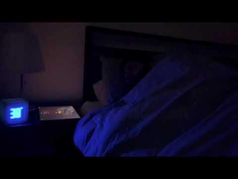
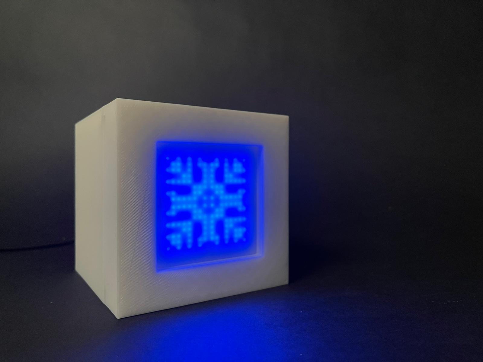
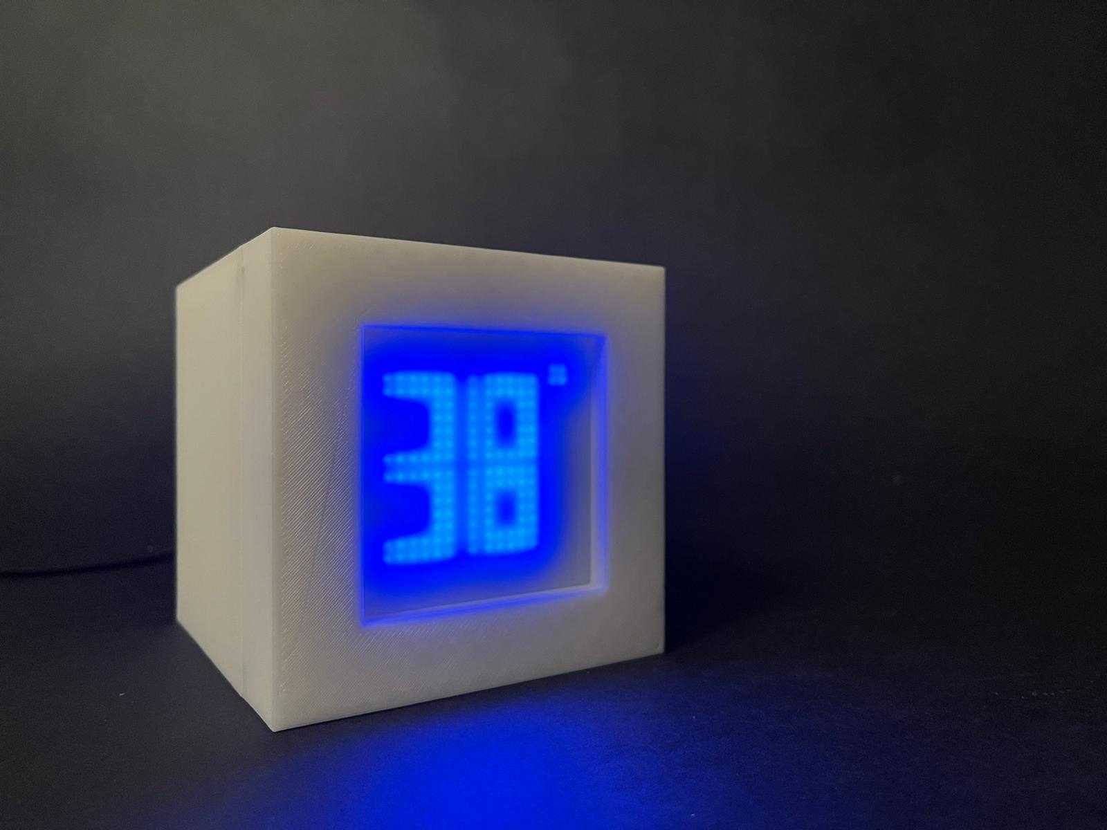
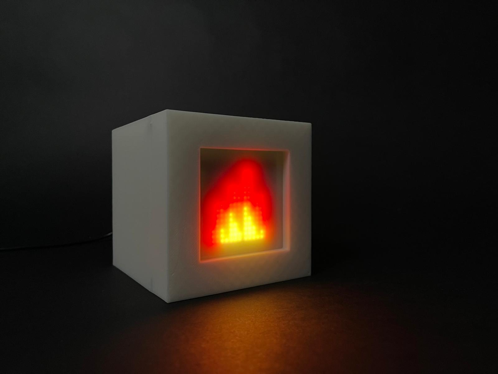
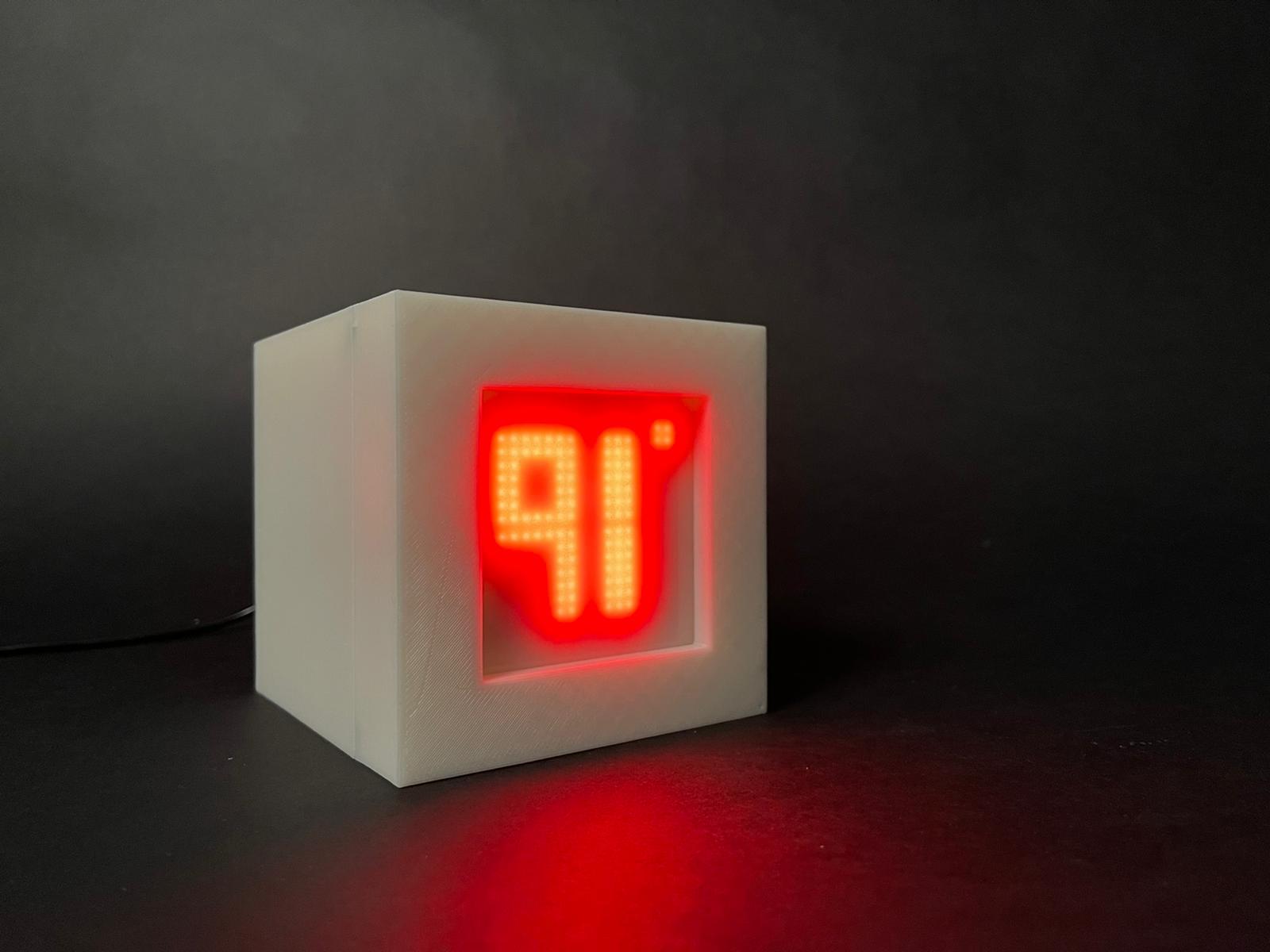
Hi, everyone! This is my nightstand thermostat that shows what the outside temperature is. This product was made for those that fall into the daily routine of checking their phone to know what the temperature is every morning.
This instructable will also serve as a guide to help you get started using Arduino board Uno and Adafruit's Dotstar Matrices, so feel free to follow along!
Enjoy!
Supplies
1 Arduino Board Uno
4 Adafruit Dotstar Matrices
Soldering Iron
wire
3D Printer
Super Glue
8 Neodymium magnets
Arrange Dotstar Matrices and Solder
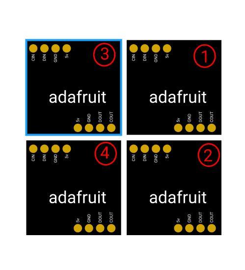
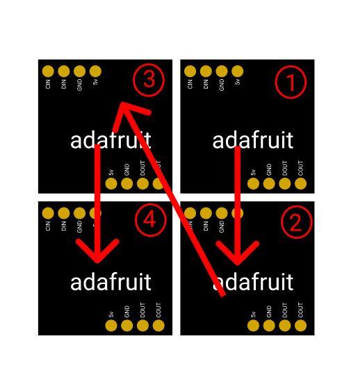
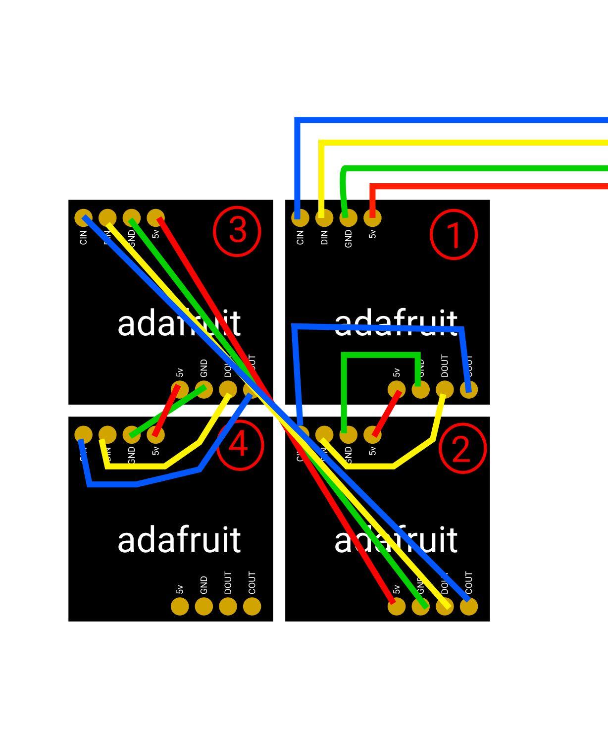
Once you have your 4 Adafruit Dotstar Matrices in hand you can go ahead and arrange them. It is very important that you follow along the pictured diagrams provided in this tutorial. Once they are all aligned and in order you can go ahead a super glue them together to avoid gaps between the matrices.
tip: I would test them first with the code and later glue them together.
Once everything is lined up you can begin to solder the Dotstar Matrices. For best results, please follow the diagram provided.
Connect Matrices to Arduino Uno Board
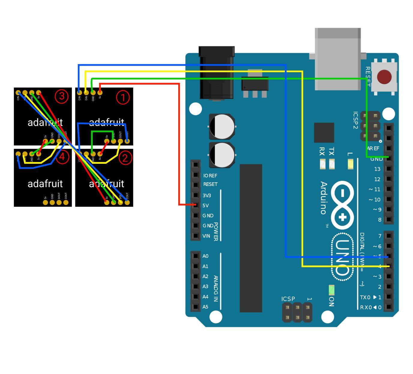
After soldering all of the wires in place, you can go ahead and connect the matrices to the Arduino Uno Board. Follow the diagram provided for best results.
Upload Code
In the tutorial, two codes are provided. One that shows a snowflake and 38 degrees F, and another one that shows a flame and 91 degrees F.
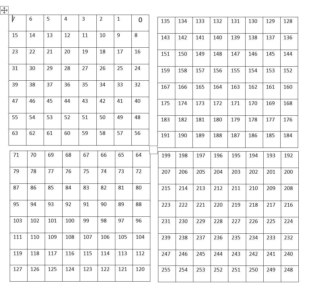
You can also experiment with the matrices and make them show whatever you want. In order to do this you need to mark down the specific pixels you want to light up and add them in the code provided. you can use the pixel chart provided in this tutorial to manually mark down the specific pixels.
3D Print Box
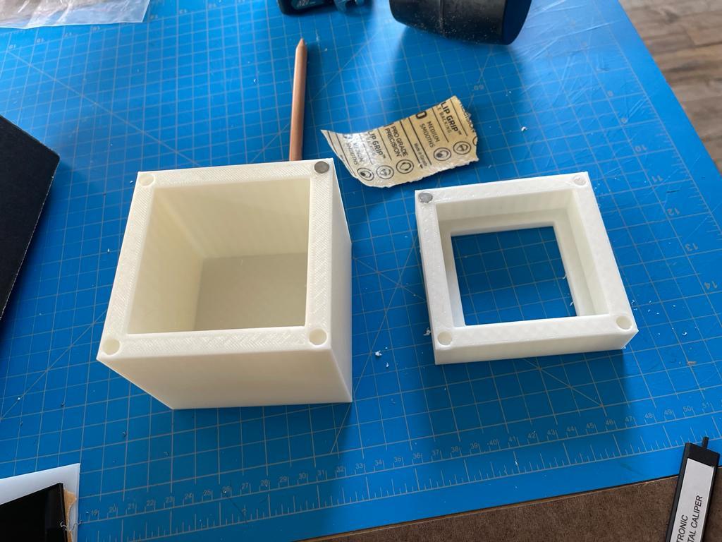
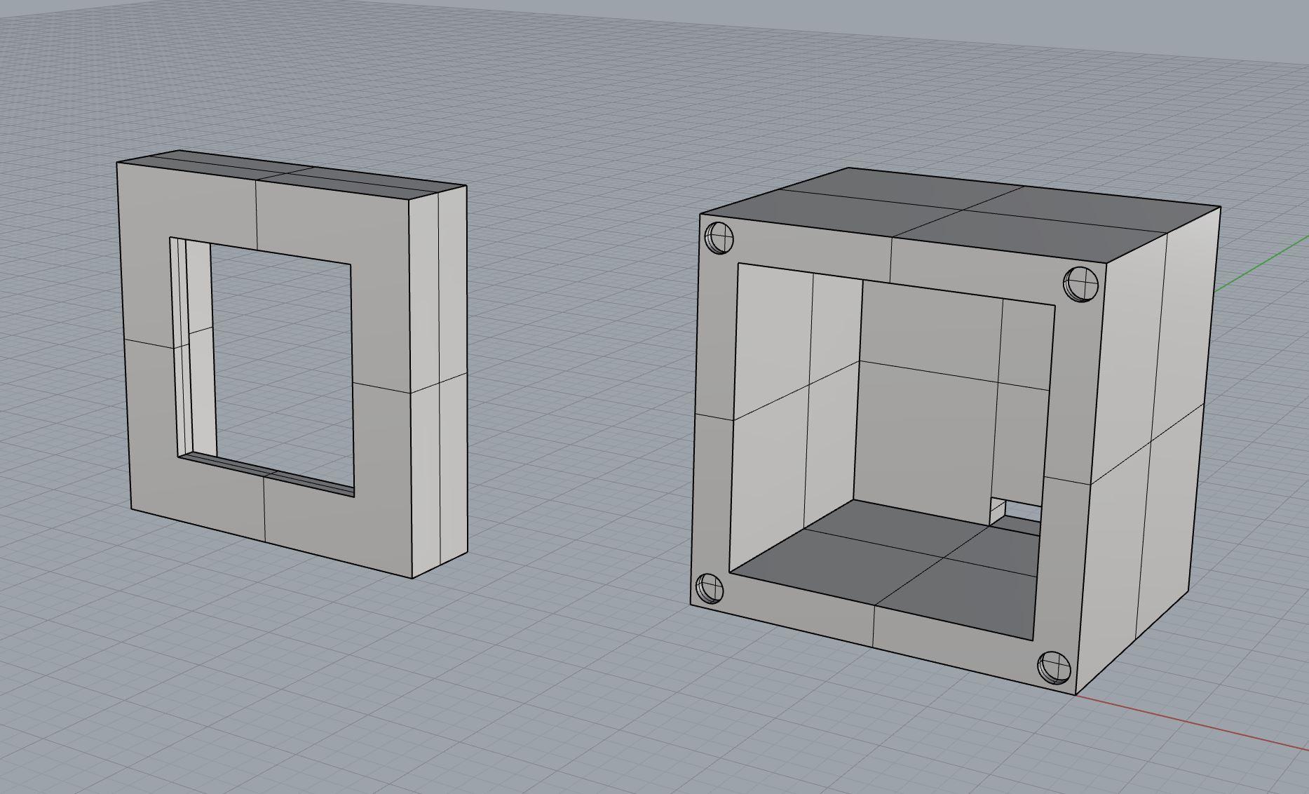
For this project, I created a 4x4 3D printed box to house all of the electronics. You don't need to have it 3D printed, but you can use the STL files provided to print your own.
Place Magnets, Acrylic Screen and Matrices
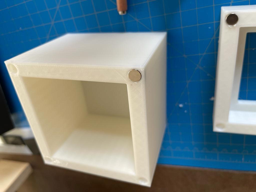
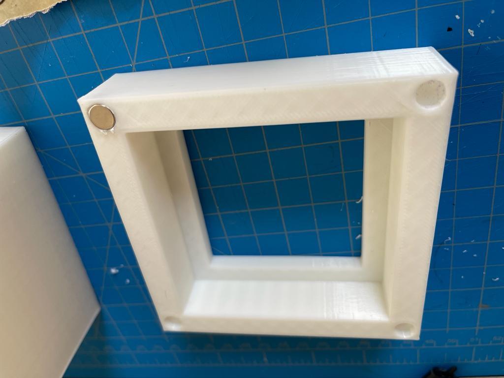
If you used the STL files provided, you might have noticed that there are 8 slots around the corners of both parts printed. These are meant for the neodymium magnets. These magnets are going to provide us with easy in and out of the box in order to arrange the electronics inside. you might need to sand or drill a little bit for the magnets to easily go in.
After doing this, you can go ahead and super glue a piece of semi translucent acrylic from the inside of the lid. Once that's done, you can glue the matrices to the acrylic piece by using hot glue. Make sure to put the glue around the frame of the matrices and not on top of the LEDs. Make sure that the matrices sit flush against the acrylic.
Place Arduino Board Inside of Box
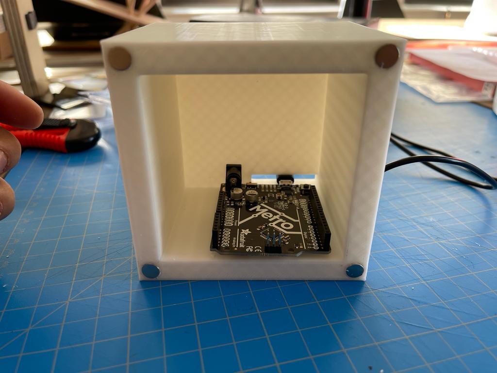
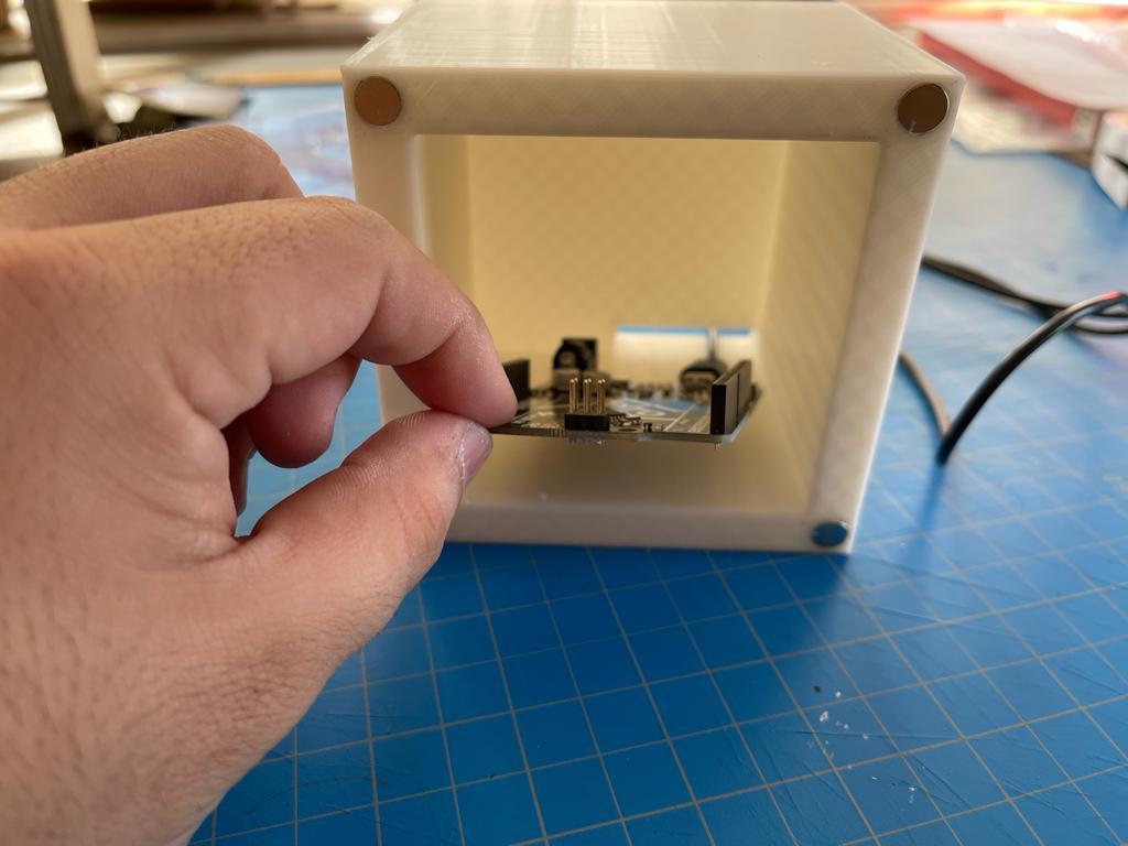
to place the arduino board to the box you first need to align the power port to the hole in the back of the box. This hole is for the power cable to slip through once everything is put together. Put hot glue at the bottom of the Arduino board and glue it inside.
Final Step
After placing the arduino board you're ready to connect the matrices to the arduino board (use diagram provided earlier) and snap the two pieces of the box together.
Connect the power cable, upload the code and you're ready to go!
Enjoy!