AVR Microcontroller Fuse Bits Configuration. Creating and Uploading in the Flash Memory of Microcontroller the LED Blinking Program.
by malcomoffice in Circuits > Microcontrollers
10863 Views, 5 Favorites, 0 Comments
AVR Microcontroller Fuse Bits Configuration. Creating and Uploading in the Flash Memory of Microcontroller the LED Blinking Program.

In this case we will create simple program in C code and burn it into the memory of the microcontroller. We will write our own program and compile the hex file, using the Atmel Studio as the integrated development platform. We will configure fuse bits and upload hex file into the memory of the AVR ATMega328P microcontroller, using our own programmer and software AVRDUDE.
AVRDUDE - is a program for downloading and uploading the on-chip memories of Atmel’s AVR microcontrollers. It can program the Flash and EEPROM, and where supported by the serial programming protocol, it can program fuse and lock bits.
Writing Program and Compile the Hex File, Using the Atmel Studio
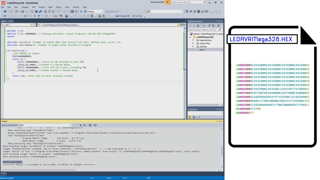
If you don’t have Atmel Studio, you should download and install it: https://www.microchip.com/mplab/avr-support/atmel-...
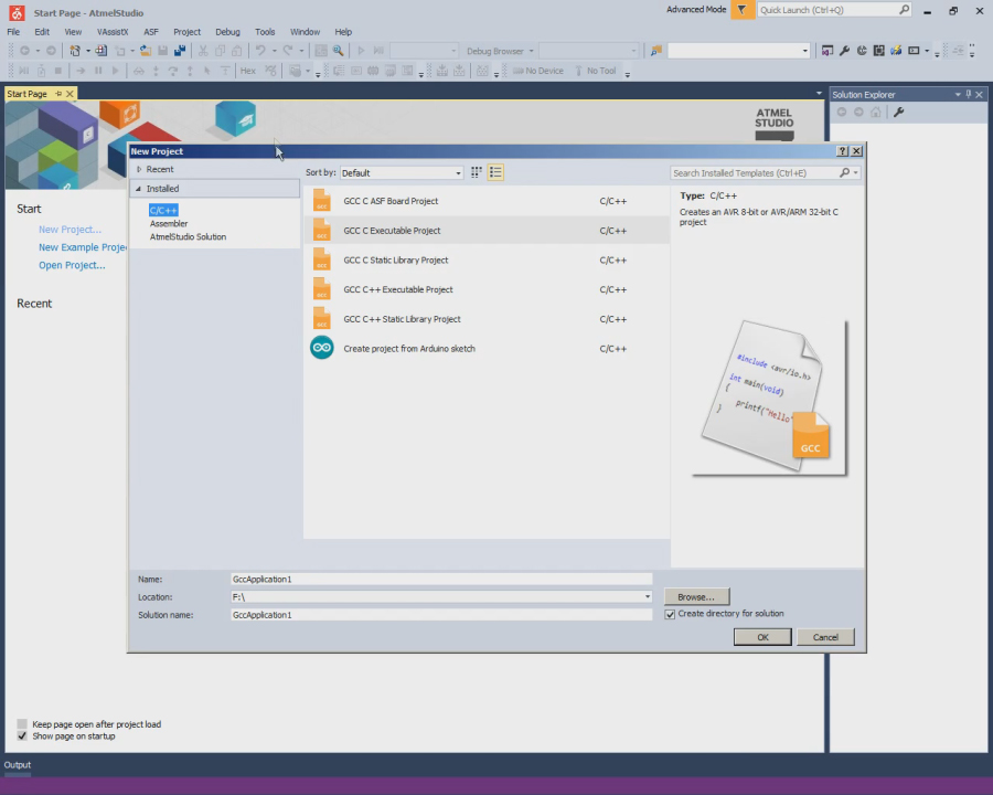
This project will use C, so select the GCC C Executable Project option from the template list to generate a bare-bones executable project.
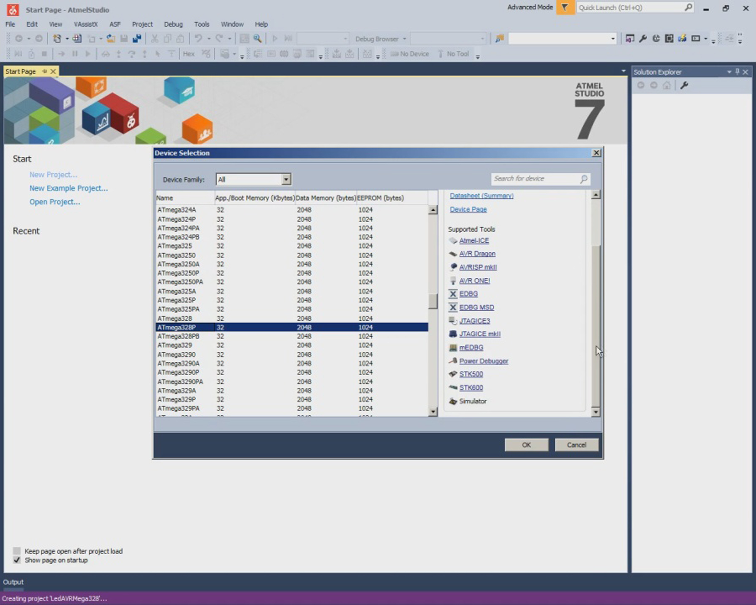
Next, it is necessary to specify which device the project will be developed for. This project will be developed for the AVR ATMega328P microcontroller.
Type the code of program in the Main Source Editor area of Atmel Studio. The Main Source Editor – This window is the main editor for the source files in the current project. The editor has spell check and auto complete features.
1. We must tell compiler at what speed our chip is running to that it can calculate delays properly.
#ifndef F_CPU
#define F_CPU 16000000UL // telling controller crystal frequency (16 MHz AVR ATMega328P)
#endif
2. We include the preamble, which is where we put our include information from other files, which defines global variables and functions.
#include <avr/io.h> //header to enable data flow control over pins. Defines pins, ports, etc.
#include <util/delay.h> //header to enable delay function in program
3. After the preamble comes the main() function.
int main(void) {The main() function is unique and set apart from all other functions. Every C program must have exactly one main() function. Main() is where the AVR starts executing your code when the power first goes on, so it's the entry point of the program.
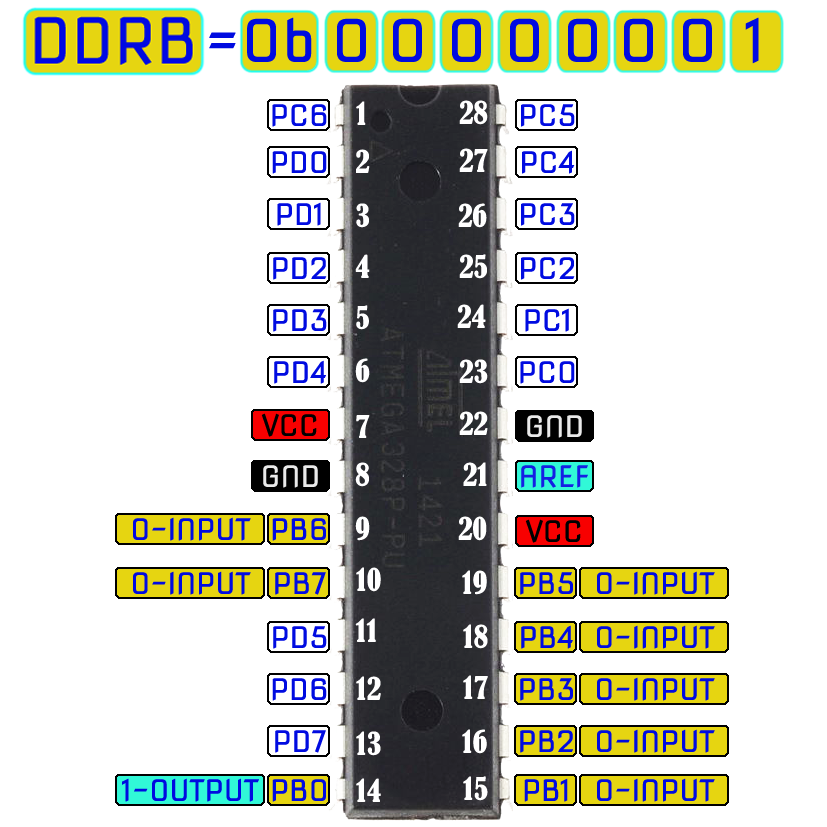
4.Set pin 0 of the PORTB as output.
DDRB=0b00000001; //Set PORTB1 as output
We do this by writing a binary number to the Data Direction Register B. The Data Direction Register B allows us to make the bits of register B input or output. Writing a 1 makes them output, while a 0 would make them input. Being that we are attaching an LED to act as output, we write a binary number, making the pin 0 of PORT B as output.
5. Loop.
while (1) {
This statement is a loop, often referred to as the main loop or event loop. This code is always true; therefore, it executes over and over again in an infinite loop. It never ceases. Therefore, LED will be blinking in an infinity, unless power is shut off from the microcontroller or the code is erased from program memory.
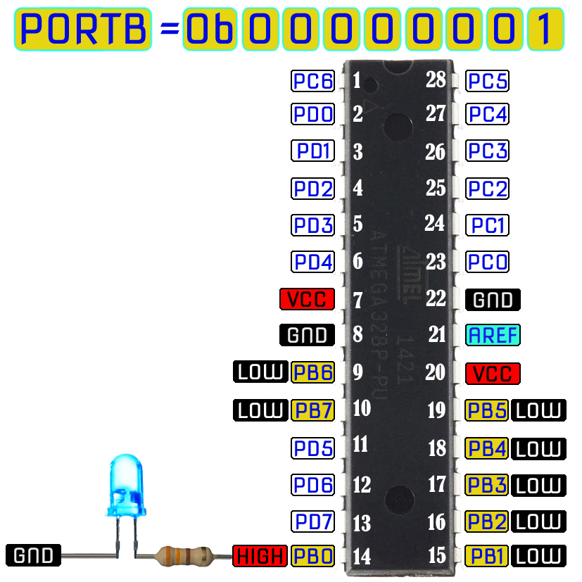
6. Turn on LED attached to port PB0
PORTB= 0b00000001; //turns on LED attached to port PB0
This line, gives a 1 to the PB0 of PortB. PORTB is a hardware register on the AVR chip that contains 8 pins, PB7-PB0, going from left to right. Putting a 1 at the end gives a 1 to PB0; this sets PB0 high which turns it on. Therefore, the LED attached to pin PB0 will turn on and light up.
7. Delay
_delay_ms(1000); //creates a 1-second delay
This statement create a 1-second delay, so that the LED turns and stays on for exactly 1 second.
8. Turn off all B pins, including PB0
PORTB= 0b00000000; //Turns off all B pins, including PB0
This line turns off all 8 Port B pins, so that even PB0 is off, so the LED turns off.
9. Another delay
_delay_ms(1000); //creates another 1-second delay
It turns off exactly for 1 second, before starting the loop all over again and encountering the line, which turns it back on, repeating the process all over. This happens infinitely so that the LED constantly blinks on and off.
10. Return statement
  }
  return (0); //this line is never actually reached
}
The last line of our code is a return(0) statement. Even though this code is never executed, because there is an infinite loop which never ends, for our programs that run on desktop computers, it's important for the operating system to know whether they ran correctly or not. For that reason, GCC, our compiler, wants every main() to end with a return code. Return codes are needless for AVR code, which runs freestanding of any supporting operating system; nevertheless, the compiler will raise a warning if you don't end main with return().
The final step is the building the project. It means compiling and finally linking all object files to generate the executable file (.hex) file. This hex file is generated inside the folder Debug which is inside the Project folder. This hex file is ready to be loaded into the microcontroller chip.
Changing the Default Configuration of the Micro Controller Fuse Bits
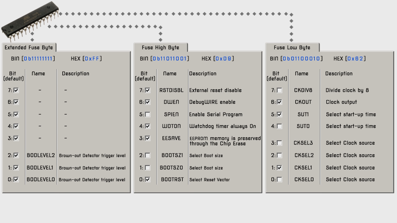

It is important to remember that some of the fuse bits can be used to lock certain aspects of the chip and can potentially brick it (make it unusable).
There are a total of 19 fuse bits that are used in the ATmega328P, and they are separated into three different fuse bytes. Three of the fuse bits are contained in the "Extended Fuse Byte", eight are contained in the "Fuse High Byte," and eight more are contained in the "Fuse Low Byte". There is also a forth byte that is used to program the lock bits.
Each byte is 8 bits and each bit is a separate setting or flag. When we talk about setting, not setting, programmed, not programmed fuses we are actually using binary. 1 means not set, not programmed and a zero means set, programmed. When programming the fuses you can use binary notation or more commonly hexadecimal notation.
ATmega 328P chips have a built in RC oscillator which has a 8 MHz frequency. New chips are shipped with this set as the clock source and the CKDIV8 fuse active, resulting in a 1 MHz system clock. The startup time is set to maximum and time-out period enabled.
New ATMega 328P chips generally have the following fuse settings:
Low fuse = 0x62 (0b01100010)
High fuse = 0xD9 (0b11011001)
Extended fuse = 0xFF (0b11111111)
We will be use ATmega 328 chip with an external 16MHz crystal. Therefore, we need to program bits of "Fuse Low Byte" accordingly.
1. Bits 3-0 control the oscillator choice, and the default setting of 0010 is to use the calibrated internal RC oscillator, which we don't want. We want the low power crystal oscillator operation from 8.0 to 16.0 MHz, so bits 3-1 (CKSEL[3:1]) should be set to 111.
2.Bits 5 and 4 control the startup time, and the default setting of 10 is for a startup delay of six clock cycles from power-down and power-save, plus an additional startup delay of 14 clock cycles plus 65 milliseconds from reset.
To be on the safe side for a low power crystal oscillator, we want the maximum delay possible of 16,000 clock cycles from power-down and power-save, so SUT[1] should be set to 1, plus an additional startup delay of 14 clock cycles plus 65 milliseconds from reset, so SUT[0] should be set to 1. In addition, CKSEL[0] should be set to 1.
3. Bit 6 controls the clock output to PORTB0, which we don't care about. So, bit 6 can be left set to 1.
4. Bit 7 controls the divide-by-8 operation and the default setting of 0 has the feature enabled, which we don't want. So, bit 7 needs to be changed from 0 to 1.
Therefore, the new Fuse Low Byte should be 11111111 which, in hexadecimal notation, is 0xFF.
To program bits of the "Fuse Low Byte" we can use our programmer (https://www.instructables.com/id/ISP-Programmer-fo...) and software AVRDUDE. AVRDUDE is a command-line utility that is used to download from and upload to Atmel microcontrollers.
Download AVRDUDE: http://download.savannah.gnu.org/releases/avrdude/...
First, we must add describe our programmer to the configuration file of AVRDUDE. On Windows the configuration file is usally in the same location as the executable file of AVRDUDE.
Pastе the text in configuration file avrdude.conf:
# ISPProgv1
programmer
  id    = " ISPProgv1";
  desc  = "serial port banging, reset=dtr sck=rts mosi=txd miso=cts";
  type  = "serbb";
  connection_type = serial;
  reset = 4;
  sck   = 7;
  mosi  = 3;
  miso  = 8;
;
Before starting the AVRDUDE, we must connect the microcontroller to the programmer, according to the scheme.
Open DOS prompt window.
1. To view the list of programmer that avrdude is supported type command avrdude -c c. If all is well, the list should have programmer id "ISPProgv1"
2. To view the list of Atmel devices that avrdude is supported type command avrdude -c ISPProgv1. The list should have device m328p for Atmel ATMega 328P.
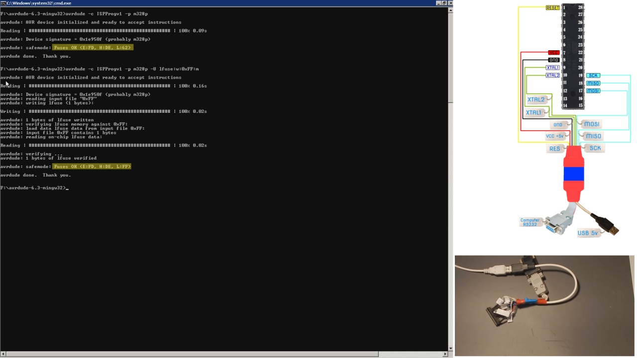
Next, type avrdude -c ISPProgv1 –p m328p, the command tell avrdude what programmer is being used and what Atmel microcontroller is attached. It presents the ATmega328P signature in hexadecimal notation: 0x1e950f. It presents the fuse bit programming currently in the ATmega328P also in hexadecimal notation; in this case, fuse bytes are programmed per factory default.
Next, type avrdude -c ISPProgv1 –p m328p –U lfuse:w:0xFF:m, It is a command to tell avrdude what programmer is being used and what Atmel microcontroller is attached and to change the Fuse Low Byte to 0xFF.
Now the clock signal should come from low power crystal oscillator.
Burning the Program Into the Memory of the ATMega328P Microcontroller
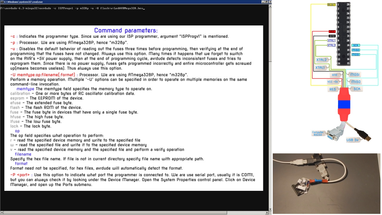
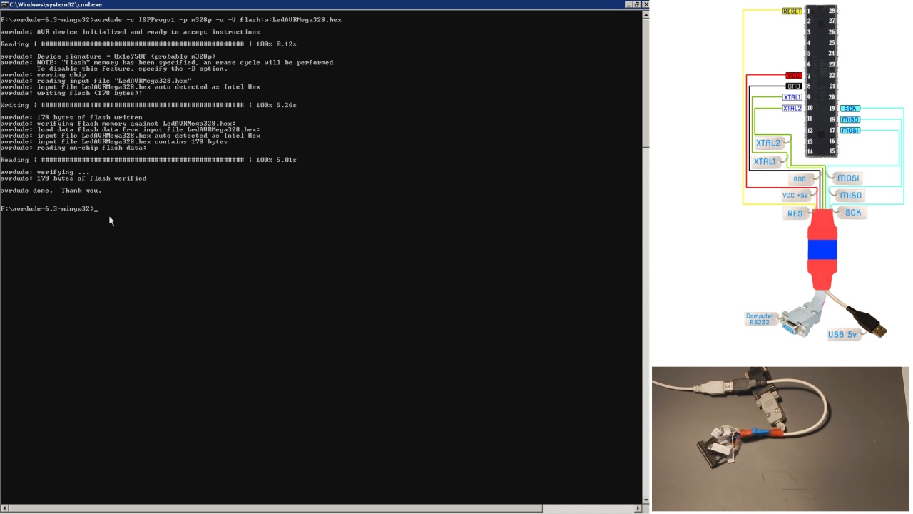
First, copy the hex file of program we made at the beginning of the instruction in to AVRDUDE directory.
Then, type in DOS prompt window the command avrdude –c ISPProgv1 –p m328p –u –U flash:w:[name of your hex file]
The command writes hex file to the microcontroller’s memory. Now, the microcontroller works in accordance with the instructions of our program. Let's check it out!
Check Microcontroller Works in Accordance With the Instructions of Our Program
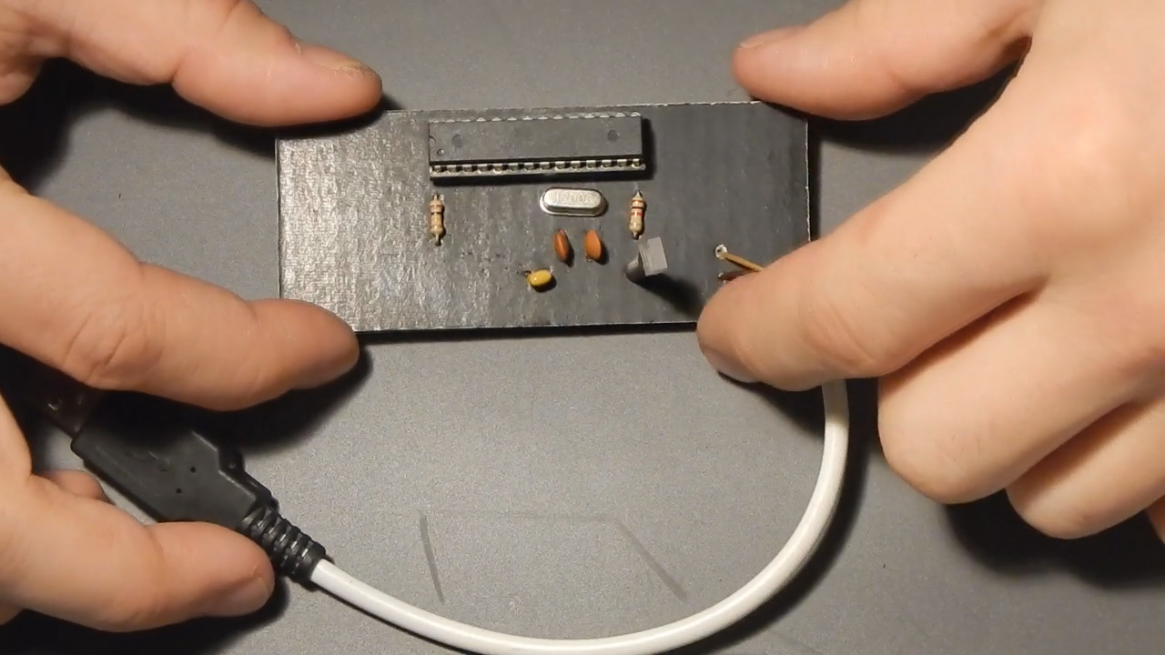
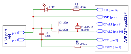
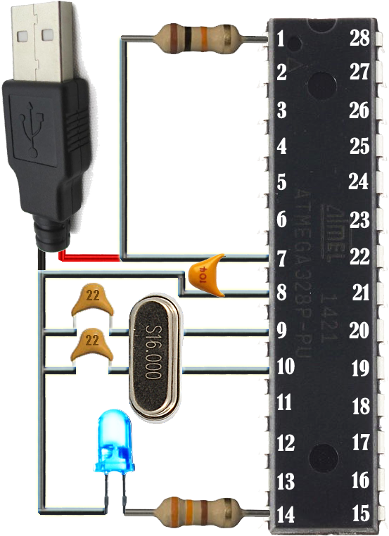
Connect components in accordance with schematic diagram of the AVR Blinking LED Circuit.
First, we need power, as all AVR circuits do. About 5 volts of power is sufficient for operation of the AVR chip. You can get this either from batteries or a DC power supply. We connect +5V of power to pin 7 and connect pin 8 to ground on the breadboard. In between both pins, we place a 0.1μF ceramic capacitor to smooth out the power of the power supply so that the AVR chip gets a smooth power line.
The 10KΩ resistor is used to provide Power On Reset (POR) to the device. When the power is switched ON, voltage across capacitor will be zero so the device resets (since reset is active low), then the capacitor charges to VCC and the reset will be disabled.
We connect the anode of our LED to AVR pin PB0. This is pin 14 of the ATMega328P. Since it is an LED, we want to limit current flowing to the LED so it doesn't burn out. This is why we place a 330Ω resistor in series with the LED. The cathode of the LED gets connected to ground.
16 MHz crystal is used to provide clock for the Atmega328 microcontroller and 22pF capacitors are used to stabilize the operation of crystal.
These are all the connections necessary to light up the LED. Power supply.
Ok. LED is blinking with one-second delay. The work of the microcontroller corresponds to our tasks.
Conclusion
Admittedly, that was a long process for just flashing an LED, but the truth is that you have successfully cleared major hurdles: creating a hardware platform for programming an AVR microcontroller, Using the Atmel Studio as the integrated development platform, using AVRDUDE as software for configuring and programming an AVR microcontroller.
If you want to keep up to date on my base microcontrollers projects, subscribe to my YouTube! Watching and sharing my videos is way to support what I do.