ATtiny Clock
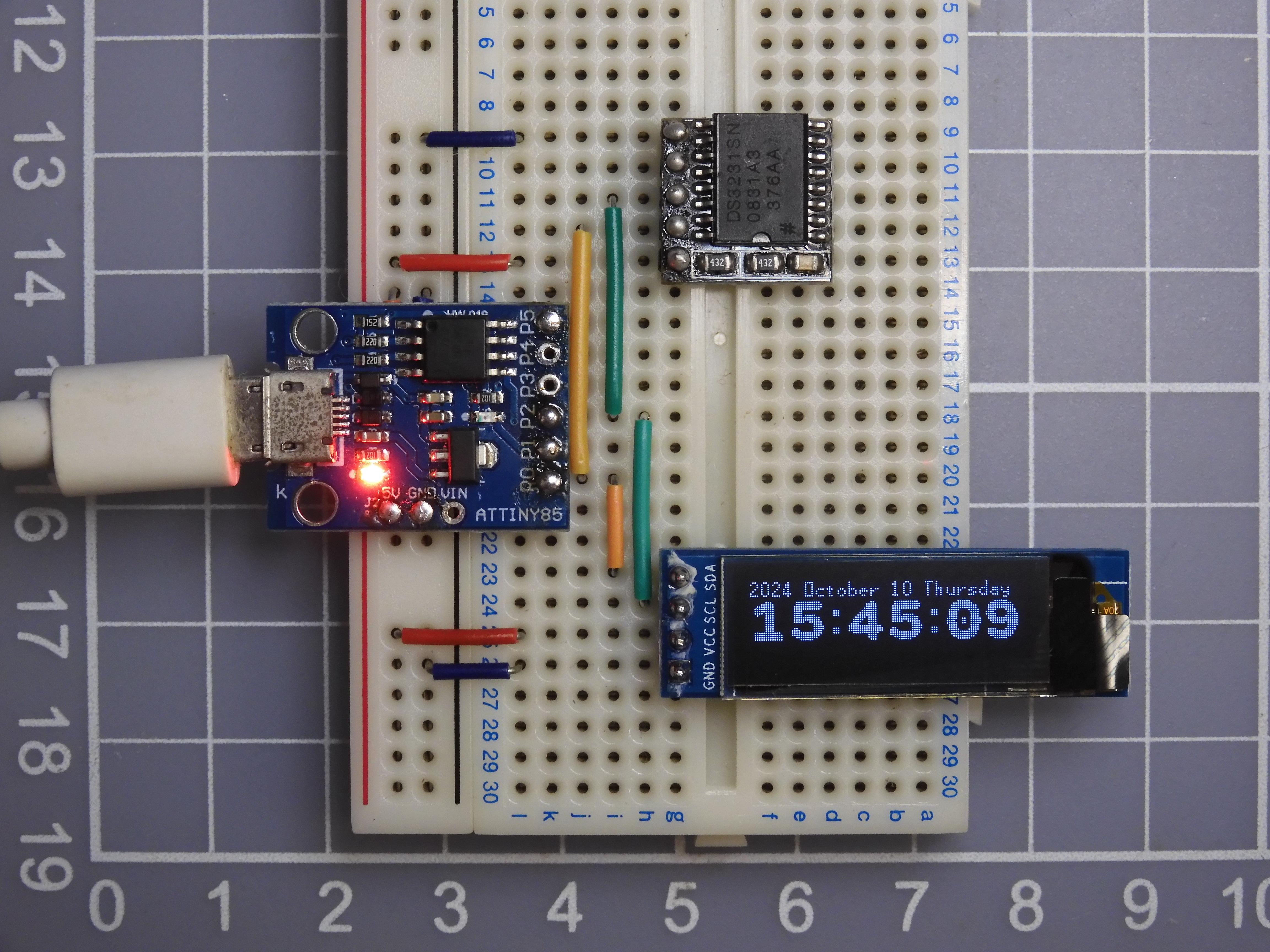

This instructables show how to use 3 components to build a simple digital clock.
This is a simplified design from my previous project, ATtiny Watch Core. This clock design is much simpler than previous watch design. The clock is put on the desk and direct powered by USB, so it doesn't need battery power management. It keeps the time by RTC, so no UI required to adjust time manually. And this time I use Digispark micro USB dev board, so no extract MCU programmer is required.
This project only requires a tiny dev board, a RTC module and an OLED display module, it is very suitable for a beginner to make it.
Supplies
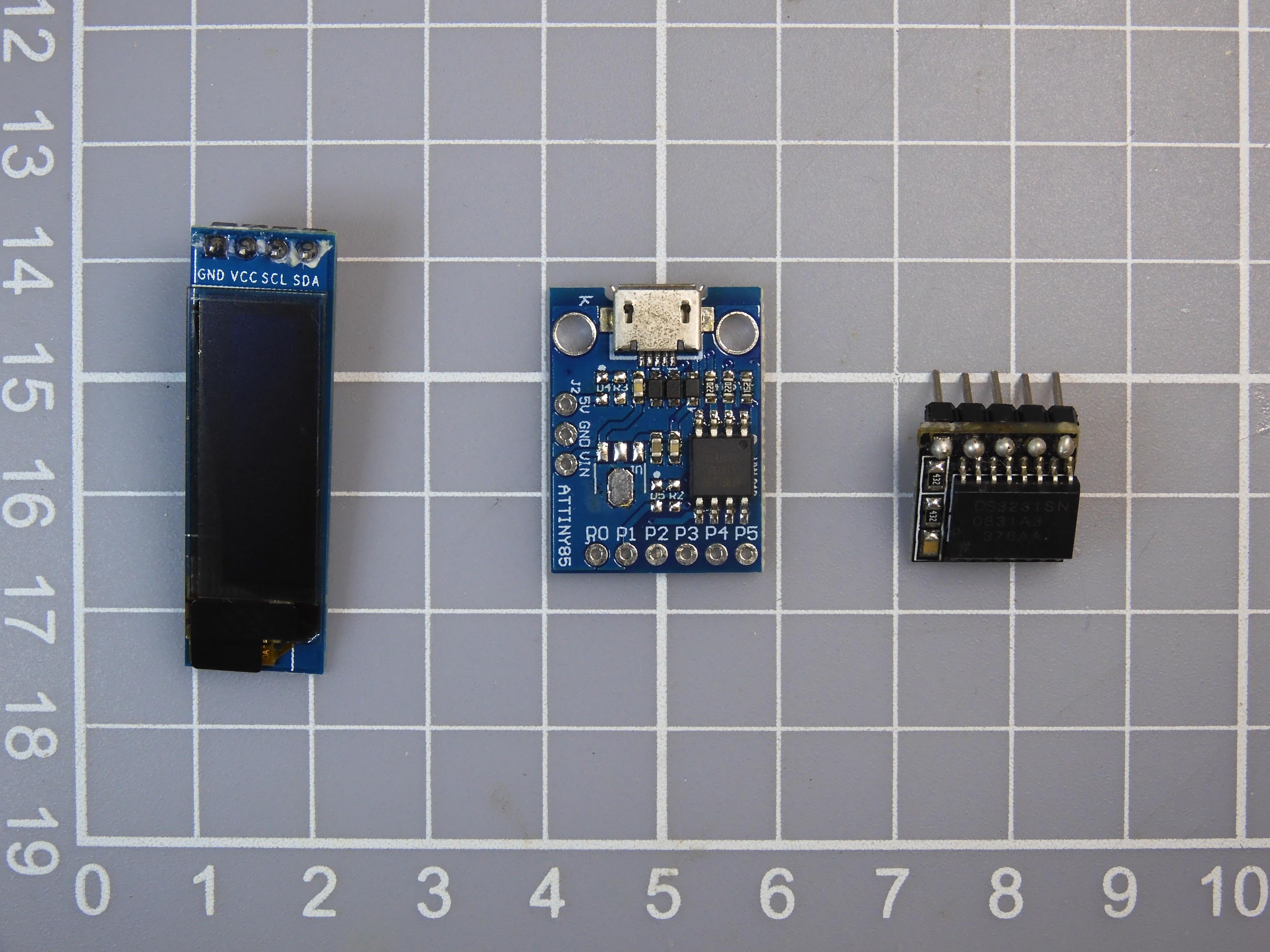
- Digispark micro USB dev board
- DS3231 RTC module (with backup battery)
- 0.91 inch 128x32 SS1306 OLED display module
- breadboard and breadboard wires
What Is Digispark?
Digispark is a 2012 kickstarter project. The original design is USB port A interface, then micro USB version appear. Now you may found clone version with USB Type C in the market. The original project is over 10 years and their web site already gone. But time proved it is a good tiny design, it still a good dev board for many simple projects.
Ref.:
https://www.kickstarter.com/projects/digistump/digispark-the-tiny-arduino-enabled-usb-dev-board
https://www.instructables.com/Digispark-DIY-The-smallest-USB-Arduino/
What Is RTC?
A real-time clock (RTC) is an electronic device (most often in the form of an integrated circuit) that measures the passage of time.
RTCs are present in almost any electronic device which needs to keep accurate time of day.
This project use a DS3231 RTC module, thanks to Raspberry Pi, it is a common RTC module in electronics hobbyist market.
Note:
RTC requires a backup battery to retain the time, but I found some module not included a battery. If no backup battery, RTC cannot do the job in most case. So please make sure your RTC module has a backup battery before using it.
Digispark Pins
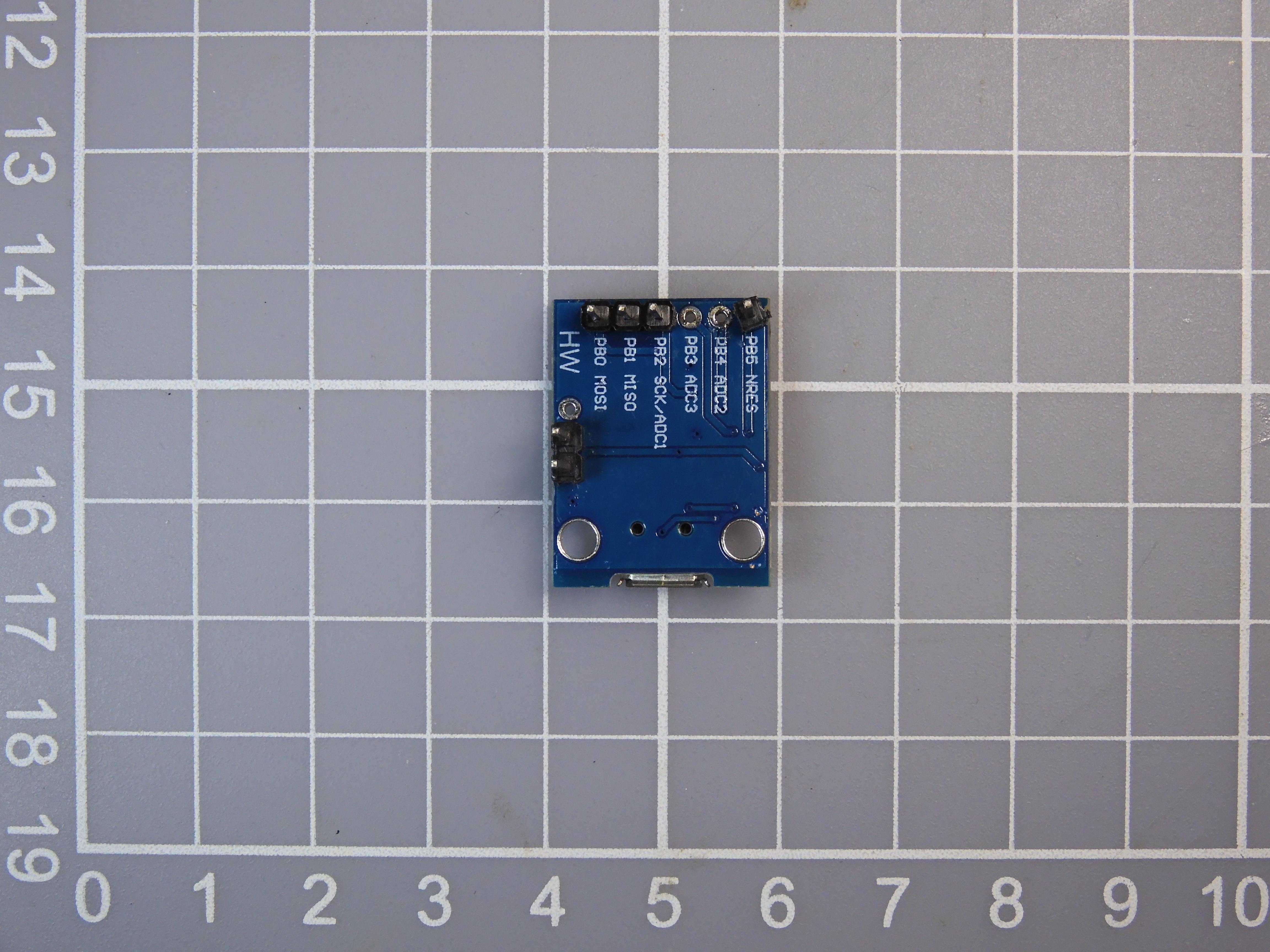
This project use breadboard for simple wire connection. You need soldering some Digispark pin headers before that.
The power pins have 3 pins, there are 5V, GND and VIN. We need 5V and GND pins to power the other 2 modules and should leave VIN alone not soldered.
The GPIO pins are from PB0 to PB5, you can all soldering it. However, since PB3 and PB4 is actually used for USB communication, so I suggest not soldering it. It may introduce upload program problems, if it connect to something that will pull-up or pulldown the pins.
In this project, only 5V, GND, PB0(I2C SDA), PB2(I2C SCL) four pins are used.
Simple Wire Connection
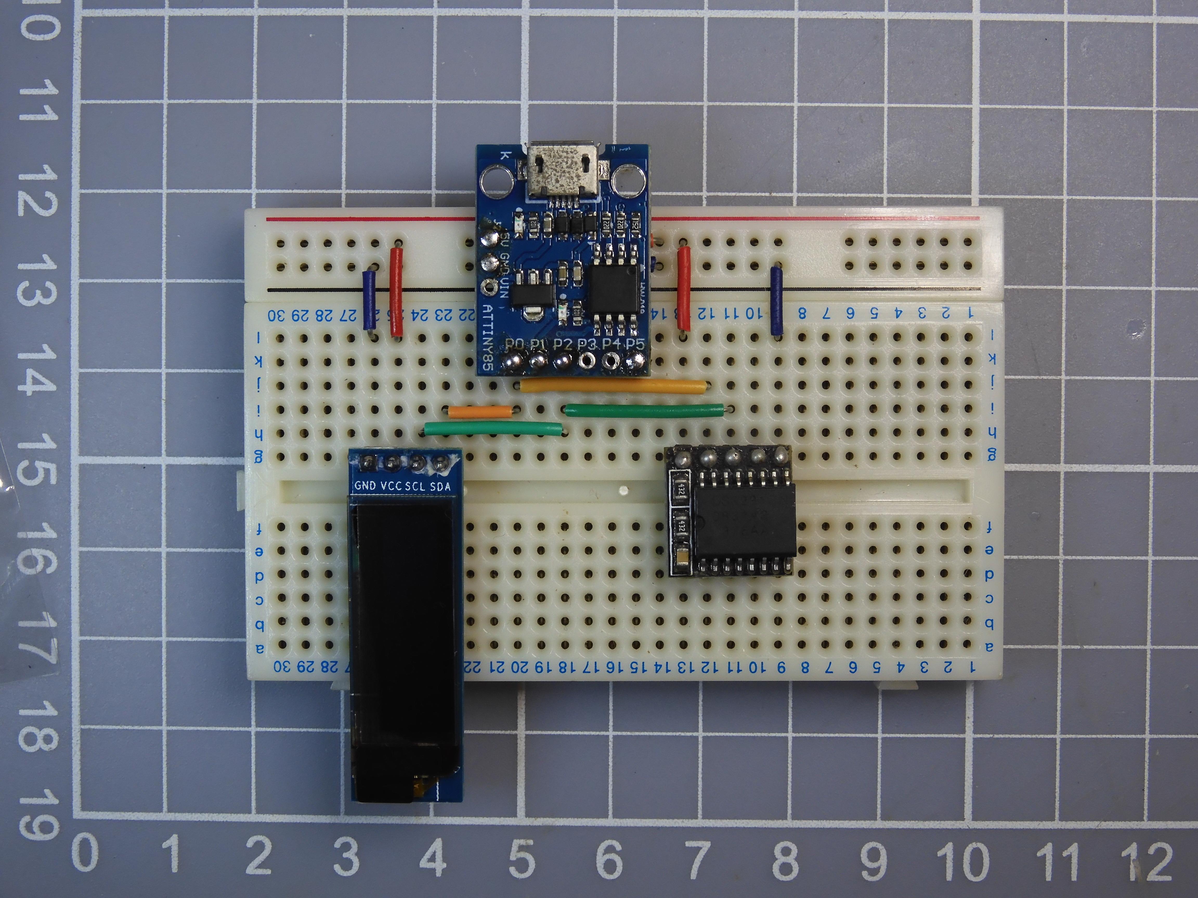
Both RTC and OLED module are communicate with I2C interface, so the connection is relatively simple.
Here are the connection summary:
Simple Program Design

The program design is also very simple, it read the time data from RTC and then display to OLED and loop forever.
Software Preparation

Arduino IDE
Download and install Arduino IDE latest 1.x version if not yet:
https://www.arduino.cc/en/software
ATTinyCore
Follow installation step to add ATTinyCore support if not yet:
DS3231
Open Arduino IDE Library Manager by selecting "Tools" menu -> "Manager Libraries...". Search "DS3231" and press "install" button.
Download Source Code
Please download the source code at Github:
https://github.com/moononournation/ProjectMINTIA
Note:
This project is part of "Project MINTIA", further update will coming soon...
Initial RTC Time


This simple project does not have UI to adjust the time. It should not have problems since the RTC can keep the time.
But we still need to initial the RTC time at the first time. We can use a simple program and simply use the compile time to set the RTC. The compiler can pass "__date__" and "__time__" as macro to the code, but if you want the day of week value correct, we need the UNIX timestamp to direct set epoch value. I used the jerabaul29's sample marco code to do the job.
Here are the initial steps:
- Open DS3231SetTime.ino in Arduino IDE
- Select Tools menu -> Board: "ATtiny85 (Micronucleus / DigiSpark)"
- Press Upload button
- Wait compile finish and ask for plugin the Digispark
- Plugin the Digispark
- Wait upload finish
- The OLED do not have any display yet, please do not unplug until upload the main program
Note:
There will have few seconds time gap between compile time and the RTC actual set, it should be ok. But if you unplug and replug the Digispark the RTC will set again and the time gap will be much larger. So please do not unplug until upload the main program.
Ref.:
https://github.com/jerabaul29/Compile_time_Cpp_UNIX_timestamp
Upload Main Program
- Open ATtinyClock.ino in Arduino IDE
- Select Tools menu -> Board: "ATtiny85 (Micronucleus / DigiSpark)"
- Press Upload button
- Wait compile finish and ask for plugin the Digispark
- Plugin the Digispark
- Wait upload finish
- The OLED will show the current date and time
Enjoy!
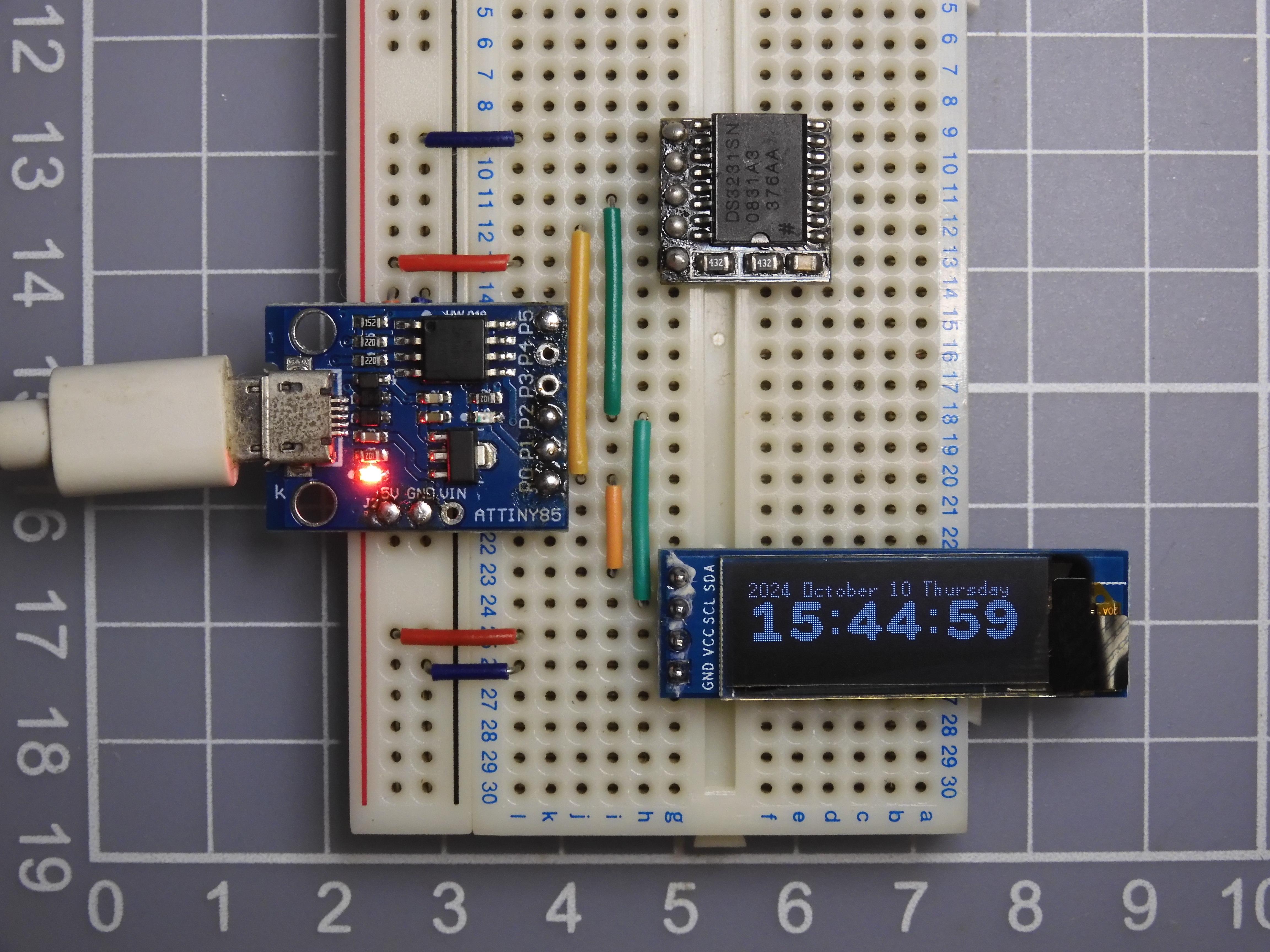
Congratulations on just completing this Arduino beginner project! Keep going!
Advanced Level: Custom Font
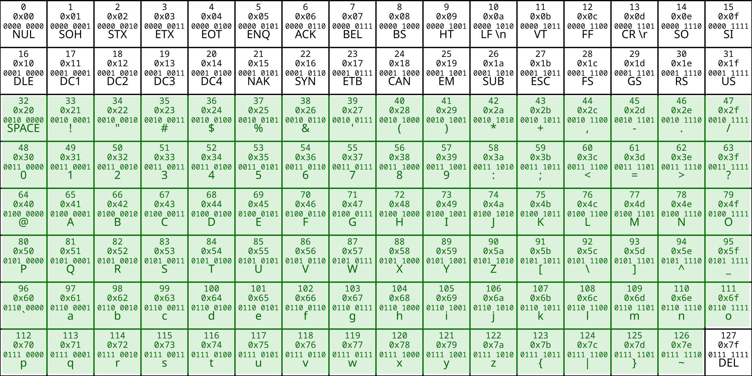

ATtiny85 only have 8 KB flash for the program, so it is limited room for the font.
For the small size font, 8 pixels height, it covered all viewable ASCII characters from SPACE(32) to "~"(126).
For the 3x size font, 24 pixels height, only characters 0-9 for display the time.
You can generate your custom 3x font by the ImageMagick command:
Then overwrite the char array details to the font_3x.h header file.
Ref.:
https://en.wikipedia.org/wiki/ASCII
Advanced Level: Parameter
SSD1306 OLED display have many different size, you can change the parameter in ssd1306.h header file change to fit your model: