ARDUINO 2D PRINTER


Hello, I'm Isaac Boateng, an electrical and electronics engineering student at Kwame Nkrumah University of Science and Technology, Ghana. Join me in this step-by-step guide to creating your own Arduino-controlled 2D printer, bringing art to life with technology.
Supplies
Materials
- Scrap DVD Drive
- Arduino uno
- L293D motor shield
- Mini servo motor
- Connecting wires
- Pen
- Solar led(green)
- Wood
Tools
- Screwdriver
- Soldering iron
- Drilling machine(optional)
- JIG saw(optional)
- Hot glue gun and sticks
- Tape Measur
Software
- Arduino IDE(https://www.arduino.cc/en/main/software )
- Inkscape (https://inkscape.org/release/inkscape-0.48/?latest=1 )
- Pronterface(https://www.pronterface.com/ )
- Code and Library
- Makerboat Gcode Inkscape extension (https://github.com/adafruit/Adafruit-Motor-Shield-library/archive/master.zip )
- Afmotor library for Arduino(https://github.com/adafruit/Adafruit-Motor-Shield-library/archive/master.zip)
- Cnc code for Arduino (https://electricdiylab.com/wp-content/uploads/2019/09/cnc-code.zip)
- GCTRL code(https://electricdiylab.com/wp-content/uploads/2019/09/GCTRL.zip )
.png)
.png)
.png)
.png)
Before building, use Fusion 360 to design your 2D printer. This step ensures precision, identifies potential challenges, and allows for iterative improvements. I opted for Fusion 360 to visualize the entire assembly, including servo motor placement and frame structure.
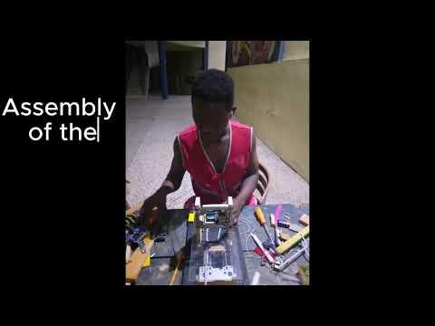
Building Your Printer Frame and Installing Components


Crafting the Frame:
- Use the Fusion 360 design as a guide to cut and assemble plywood pieces.
- Pay attention to precision for a seamless fit.
Component Placement:
- Refer to the Fusion 360 design to position stepper motors, Arduino board, and peripherals.
Secure Attachments:
- Fasten components to the frame securely to prevent vibrations.
- Organize and route wires neatly.
Preliminary Test:
- Conduct an initial test to verify proper connections before finalizing the assembly.
Final Check:
- Confirm alignment with the Fusion 360 design.
- Ensure the frame is sturdy without any flexing.
Connecting L293D Shield to DVD Motor and Servo Motor


Now, let's move on to the practical implementation. In this step, you'll connect the L293D shield to the DVD motor. Additionally, you'll integrate the servo motor into the system. This step is crucial for enabling precise control over the movement of your 2D printer.
Connecting the L293D Shield to DVD Motor:
- Detach DVD Motor: Remove the DVD motor carefully from its original housing, ensuring you preserve the necessary components.
- L293D Shield Connection: Connect the DVD motor to the L293D motor driver shield. The L293D shield acts as an interface between the Arduino and the motor, facilitating controlled movements.
- Wiring Configuration: Ensure the wiring follows the specifications of the L293D shield and the DVD motor. This step establishes a reliable connection for seamless integration.
Adding the Servo Motor:
- Servo Motor Integration: Integrate the servo motor into the system. The servo motor's precise control is invaluable for certain functionalities, adding versatility to your 2D printer.
- Secure Connection: Ensure a secure and stable connection between the servo motor and the control board. This step is vital for accurate positioning during the printing process.
Testing Connections:
- Verify Wiring: Double-check all connections to ensure accuracy. Miswiring can lead to erratic behavior, so attention to detail is crucial.
- Test Movements: Execute simple movements using the Arduino code to verify that the DVD motor and servo motor respond as expected. This preliminary testing ensures that your hardware setup is on the right track.
Uploading Code to the Arduino Board


Now, let's move on to programming the Arduino board to bring intelligence to our 2D printer.
- Accessing the Code:
- Retrieve the Arduino code designed for the 2D printer. This code dictates how the Arduino controls the stepper motors for precise movements.
- Connecting Arduino:
- Use a USB cable to connect the Arduino board to your computer.
- Opening Arduino IDE:
- Launch the Arduino IDE on your computer.
- Loading the Code:
- Open the code file in the Arduino IDE.
- Review the code to understand its functionality.
- Selecting Board and Port:
- In the Arduino IDE, choose the correct board type (e.g., Arduino Uno) and port.
- Uploading Code:
- Click the "Upload" button to transfer the code to the Arduino board.
- Monitor the IDE for any error messages.
- Verifying Success:
- Confirm a successful upload by checking for the "Done uploading" message in the IDE.
//Isaac Boateng
//Arduino 2d printer
#include <Servo.h>//make sure to install the libraries on your IDE


#include <AFMotor.h>


#define LINE_BUFFER_LENGTH 512


char STEP = MICROSTEP ;

const int penZUp = 120;
const int penZDown = 50;


const int penServoPin =10 ;


const int stepsPerRevolution = 48;


Servo penServo;

AF_Stepper myStepperY(stepsPerRevolution,1);
AF_Stepper myStepperX(stepsPerRevolution,2);


struct point {
  float x;
  float y;
  float z;
};

struct point actuatorPos;


float StepInc = 1;
int StepDelay = 1;
int LineDelay =0;
int penDelay = 50;

float StepsPerMillimeterX = 100.0;
float StepsPerMillimeterY = 100.0;

float Xmin = 0;
float Xmax = 40;
float Ymin = 0;
float Ymax = 40;
float Zmin = 0;
float Zmax = 1;


float Xpos = Xmin;
float Ypos = Ymin;
float Zpos = Zmax;

boolean verbose = false;

void setup() {

  Serial.begin( 9600 );

  penServo.attach(penServoPin);
  penServo.write(penZUp);
  delay(100);


  myStepperX.setSpeed(600);


  myStepperY.setSpeed(600);


  Serial.println("Mini CNC Plotter alive and kicking!");
  Serial.print("X range is from ");
  Serial.print(Xmin);
  Serial.print(" to ");
  Serial.print(Xmax);
  Serial.println(" mm.");
  Serial.print("Y range is from ");
  Serial.print(Ymin);
  Serial.print(" to ");
  Serial.print(Ymax);
  Serial.println(" mm.");
}


void loop()
{

  delay(100);
  char line[ LINE_BUFFER_LENGTH ];
  char c;
  int lineIndex;
  bool lineIsComment, lineSemiColon;


  lineIndex = 0;
  lineSemiColon = false;
  lineIsComment = false;


  while (1) {


    while ( Serial.available()>0 ) {
      c = Serial.read();
      if (( c == '\n') || (c == '\r') ) {
        if ( lineIndex > 0 ) {
          line[ lineIndex ] = '\0';
          if (verbose) {
            Serial.print( "Received : ");
            Serial.println( line );
          }
          processIncomingLine( line, lineIndex );
          lineIndex = 0;
        }
        else {
          // Empty or comment line. Skip block.
        }
        lineIsComment = false;
        lineSemiColon = false;
        Serial.println("ok");
      }
      else {
        if ( (lineIsComment) || (lineSemiColon) ) {
          if ( c == ')' )  lineIsComment = false;
        }
        else {
          if ( c <= ' ' ) {
          }
          else if ( c == '/' ) {
          }
          else if ( c == '(' ) {
            lineIsComment = true;
          }
          else if ( c == ';' ) {
            lineSemiColon = true;
          }
          else if ( lineIndex >= LINE_BUFFER_LENGTH-1 ) {
            Serial.println( "ERROR - lineBuffer overflow" );
            lineIsComment = false;
            lineSemiColon = false;
          }
          else if ( c >= 'a' && c <= 'z' ) {
            line[ lineIndex++ ] = c-'a'+'A';
          }
          else {
            line[ lineIndex++ ] = c;
          }
        }
      }
    }
  }
}


void processIncomingLine( char* line, int charNB ) {
  int currentIndex = 0;
  char buffer[ 64 ];
  struct point newPos;


  newPos.x = 0.0;
  newPos.y = 0.0;

  while( currentIndex < charNB ) {
    switch ( line[ currentIndex++ ] ) {
    case 'U':
      penUp();
      break;
    case 'D':
      penDown();
      break;
    case 'G':
      buffer[0] = line[ currentIndex++ ];

      buffer[1] = '\0';


      switch ( atoi( buffer ) ){
      case 0:
      case 1:

        char* indexX = strchr( line+currentIndex, 'X' );
        char* indexY = strchr( line+currentIndex, 'Y' );
        if ( indexY <= 0 ) {
          newPos.x = atof( indexX + 1);
          newPos.y = actuatorPos.y;
        }
        else if ( indexX <= 0 ) {
          newPos.y = atof( indexY + 1);
          newPos.x = actuatorPos.x;
        }
        else {
          newPos.y = atof( indexY + 1);
          indexY = '\0';
          newPos.x = atof( indexX + 1);
        }
        drawLine(newPos.x, newPos.y );

        actuatorPos.x = newPos.x;
        actuatorPos.y = newPos.y;
        break;
      }
      break;
    case 'M':
      buffer[0] = line[ currentIndex++ ];
      buffer[1] = line[ currentIndex++ ];
      buffer[2] = line[ currentIndex++ ];
      buffer[3] = '\0';
      switch ( atoi( buffer ) ){
      case 300:
        {
          char* indexS = strchr( line+currentIndex, 'S' );
          float Spos = atof( indexS + 1);
          //         Serial.println("ok");
          if (Spos == 30) {
            penDown();
          }
          if (Spos == 50) {
            penUp();
          }
          break;
        }
      case 114:
        Serial.print( "Absolute position : X = " );
        Serial.print( actuatorPos.x );
        Serial.print( "  -  Y = " );
        Serial.println( actuatorPos.y );
        break;
      default:
        Serial.print( "Command not recognized : M");
        Serial.println( buffer );
      }
    }
  }


}

void drawLine(float x1, float y1) {


  if (verbose)
  {
    Serial.print("fx1, fy1: ");
    Serial.print(x1);
    Serial.print(",");
    Serial.print(y1);
    Serial.println("");
  }


  if (x1 >= Xmax) {
    x1 = Xmax;
  }
  if (x1 <= Xmin) {
    x1 = Xmin;
  }
  if (y1 >= Ymax) {
    y1 = Ymax;
  }
  if (y1 <= Ymin) {
    y1 = Ymin;
  }


  if (verbose)
  {
    Serial.print("Xpos, Ypos: ");
    Serial.print(Xpos);
    Serial.print(",");
    Serial.print(Ypos);
    Serial.println("");
  }


  if (verbose)
  {
    Serial.print("x1, y1: ");
    Serial.print(x1);
    Serial.print(",");
    Serial.print(y1);
    Serial.println("");
  }


  x1 = (int)(x1*StepsPerMillimeterX);
  y1 = (int)(y1*StepsPerMillimeterY);
  float x0 = Xpos;
  float y0 = Ypos;


  long dx = abs(x1-x0);
  long dy = abs(y1-y0);
  int sx = x0<x1 ? StepInc : -StepInc;
  int sy = y0<y1 ? StepInc : -StepInc;


  long i;
  long over = 0;


  if (dx > dy) {
    for (i=0; i<dx; ++i) {
      myStepperX.onestep(sx,STEP);
      over+=dy;
      if (over>=dx) {
        over-=dx;
        myStepperY.onestep(sy,STEP);
      }
    delay(StepDelay);
    }
  }
  else {
    for (i=0; i<dy; ++i) {
      myStepperY.onestep(sy,STEP);
      over+=dx;
      if (over>=dy) {
        over-=dy;
        myStepperX.onestep(sx,STEP);
      }
      delay(StepDelay);
    }
  }


  if (verbose)
  {
    Serial.print("dx, dy:");
    Serial.print(dx);
    Serial.print(",");
    Serial.print(dy);
    Serial.println("");
  }


  if (verbose)
  {
    Serial.print("Going to (");
    Serial.print(x0);
    Serial.print(",");
    Serial.print(y0);
    Serial.println(")");
  }


  delay(LineDelay);
  Xpos = x1;
  Ypos = y1;
}


//  Raises pen
void penUp() {
  penServo.write(penZUp);
  delay(penDelay);
  Zpos=Zmax;
  digitalWrite(15, LOW);
    digitalWrite(16, HIGH);
  if (verbose) {
    Serial.println("Pen up!");

  }
}


void penDown() {
  penServo.write(penZDown);
  delay(penDelay);
  Zpos=Zmin;
  digitalWrite(15, HIGH);
    digitalWrite(16, LOW);
  if (verbose) {
    Serial.println("Pen down.");


  }
}
Image to G-code: Inkscape Conversion


Now, let's integrate images into our project using Inkscape and convert them into G-code for the 2D printer, Open Inkscape and import the image you want to draw with your 2D printer.
Image Adjustments:
- Scale, resize, or make any necessary adjustments to the image within Inkscape.
- Ensure that the image fits within the printable area defined by your Fusion 360 design.
Tracing Image:
- Utilize the tracing function in Inkscape to convert the image into a vector format.
- Adjust settings to achieve the desired level of detail.
Saving as SVG:
- Save the traced image as an SVG file. This file format is essential for G-code generation.
Generating G-code:
- Use a G-code generator, such as CNCjs or another appropriate software, to convert the SVG file into G-code.
- Configure the G-code parameters based on your printer's specifications.
Saving G-code:
- Save the generated G-code file to a location accessible by your 2D printer.
Printing Your Design With Pronterface

Pronterface serves as a user-friendly interface to seamlessly upload the G-code representation of your design, configure essential print settings, and then initiate the printing process on your Arduino-controlled 2D printer, transforming your digital creations into tangible and precise artwork.