ARDUINO 101 | RGB LED
This Instructable will guide you through the process of controlling an RGB LED with an Arduino and the Serial Monitor.
Supplies
1) Any Arduino board: Arduino Pro Mini
2) A breadboard: Solderless Breadboard 400 points
3) An RGB LED: RGB SMD LED Module
4) FTDI FT232RL: FT232RL USB to TTL 3.3V 5V Serial Adapter Module for Arduino
5) Female Jumper Cables: 20cm Female To Female Jumper Cable
6) FTDI driver: FT232RL DRIVER
7) Arduino IDE: Arduino IDE
CONNECTIONS
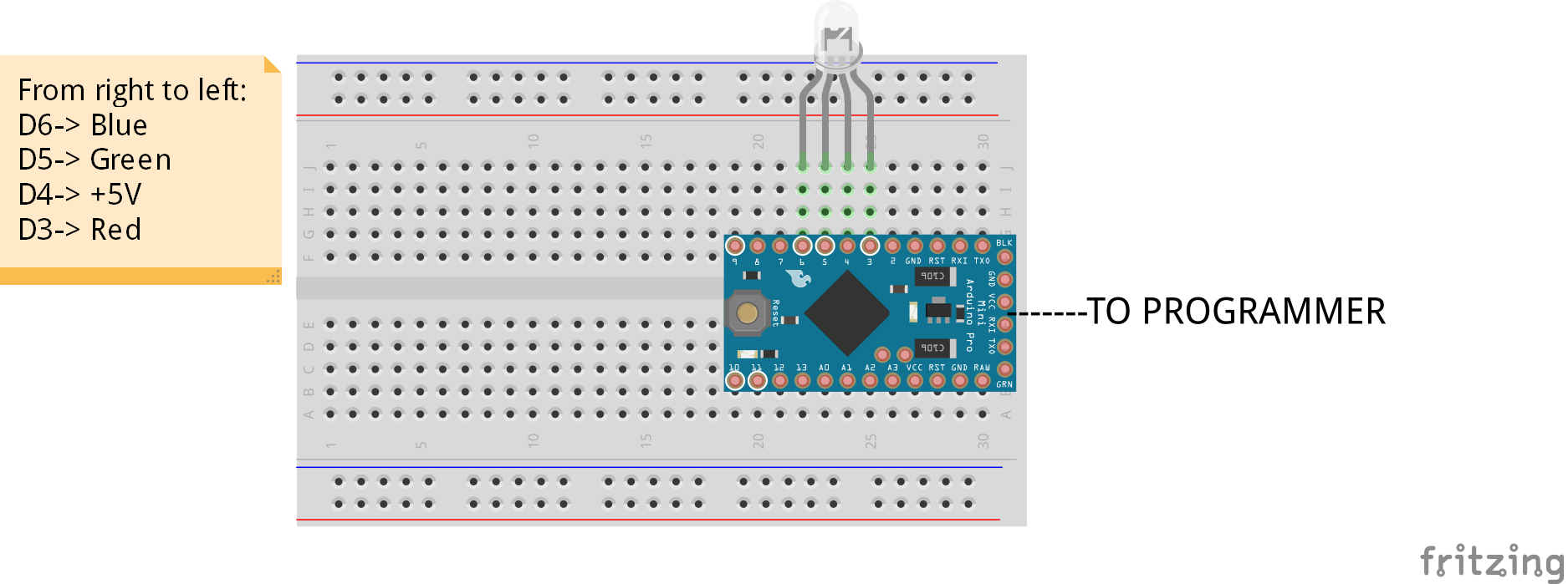

1) FOR A COMMON CATHODE RGB LED:
RED PIN OF LED -> Digital Pin 3 of Arduino
-ve 5V PIN OF LED -> Digital Pin 4 of Arduino
GREEN PIN OF LED -> Digital Pin 5 of Arduino
BLUE PIN OF LED -> Digital Pin 6 of Arduino
2) FOR A COMMON ANODE RGB LED:
RED PIN OF LED -> Digital Pin 3 of Arduino
+ve 5V PIN OF LED -> Digital Pin 4 of Arduino
GREEN PIN OF LED -> Digital Pin 5 of Arduino
BLUE PIN OF LED -> Digital Pin 6 of Arduino
Connect your Arduino to your PC.
PROGRAMMING
1) Find the code attached for your type of RGB LED.
2) Select the exact board that you are using in the BOARDS section under the TOOLS tab.
3) Select the port that the board is connected to in the PORTS section under the TOOLS tab.
4) Verify and upload the code.
CONTROLLING THE LED
SKIP TO 2:05
1) Open the Serial Monitor ( Ctrl + Shift + M ) and set the baud rate to 9600 bps and select NEWLINE.
2) Enter the RGB values in this format: R, G, B, and hit ENTER!
WHITE: 255,255,255 (Red + Green + Blue)
RED: 255,0,0 (Red)
GREEN: 0,255,0 (Green)
BLUE: 0,0,255 (Blue)
CYAN: 0,255,255 (Green+Blue)
YELLOW: 255,255,0 (Red+Green)
PURPLE: 255,0,255 (Red+Blue)
BLACK: 0,0,0 (NA/NA/NA)
Consider following us on our Instagram page: hertzandmadden