ARDUINO 101 | HC-SR501 PIR MOTION SENSOR
by HertzandMadden in Circuits > Arduino
371 Views, 2 Favorites, 0 Comments
ARDUINO 101 | HC-SR501 PIR MOTION SENSOR
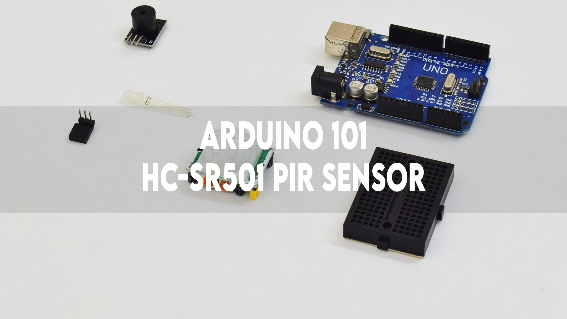
This Instructable will guide you through the process of testing an HC-SR501 PIR motion sensor using an Arduino UNO R3.
Supplies
1) Arduino UNO R3: Click here.
2) HC-SR501 PIR motion sensor: Click here.
3) 5V Buzzer: Click here.
4) Common Anode RGB LED: Click here.
5) Mini breadboard: Click here.
6) Jumper wires: Click here.
CONNECTIONS
.jpg)
.jpg)
.jpg)
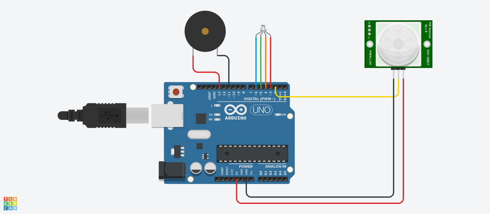
RGB LED:
Red -> D3
Green -> D5
Blue -> D6
Common Anode -> D4
BUZZER:
VCC -> D13
GND -> D11
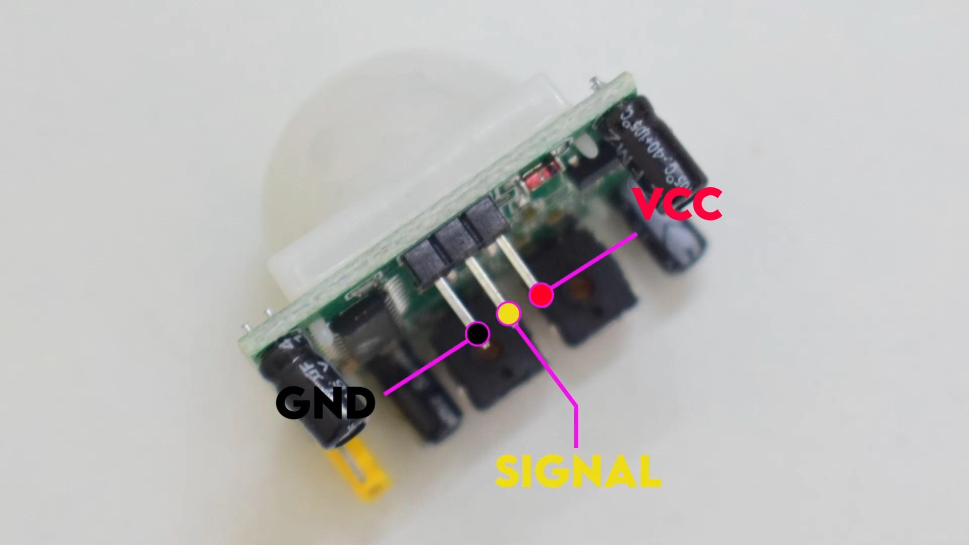
PIR SENSOR:
VCC -> 5V
GND -> GND
SIGNAL -> D2
PROGRAMMING
1) Download the code.
2) Open it and verify the same.
3) Select the right communication port and board.
4) Upload the code.
Downloads
TESTING

*SKIP TO 2:45*
The green LED glows when there is no motion being detected by the sensor.
If a motion is detected by the sensor, the light turns red and the buzzer beeps.
The light turns blue while the sensor dwells.