AMAZING DIY DESKTOP CHARGING STATION
by ahsanbilal0309 in Circuits > Tools
171 Views, 3 Favorites, 0 Comments
AMAZING DIY DESKTOP CHARGING STATION


Four-way Desktop Smart Charging Station
This is a practical intelligent multi-channel desktop charger project
Recently, I can see a lot of 166W charger kits and finished products of this project on Xianyu. I hereby declare that these are not listed by me. All my information is open source for free, and I have not received any benefits from it! This project welcomes everyone to copy and improve, and sell a limited number of finished products/kits at a suitable price (time and energy are also costs) to facilitate newcomers, but it is not commercial mass production, selling at a high price and making money. Some big guys have improved on the basis of open source code and opened the firmware for free. I would like to express my gratitude. Please work together to maintain the open source environment. The domestic open source environment is already difficult. Respect technology and developers, and open source can go further!
Supplies
Description
- Hardware:【Upper board/lower board/front panel/rear panel】gerber file/schematic source file/schematic PDF file/coordinate file/BOM file
- Firmware: [ESP32C3FN4 firmware and tools] Firmware/driver/download burning software
- Software: 【Software Engineering Source Code】esp-idf-4.4 version development environment
- Structure: 【Complete machine structure file】Includes circuit board and shell assembly files, software version Soliworks2022
- Documents: [Document manuals used in the project, etc.] Some manuals are not allowed to be circulated by the manufacturer and are not uploaded
- Data description
- The gerber files have been added, including the upper board, lower board, front panel, and rear panel, which can be directly proofed (if the upper board fails the review, just note that the board is broken and no replacement is required)
- Schematic source files added
- Added README file
- Added burning software, bootloader firmware and app firmware
- Added Structural Design folder
- Added manual folder
- Added esp32c3 usb cdc/jtag driver files
- The source code project folder has been added. I hope the big guys can help improve it. If there are any errors or questions in the code, you can submit issues for communication. Of course, it would be even better if you can help me improve the function
- The new version of the top board (Gerber_topBoard-Fix.zip) has been submitted. After modifying the border that is difficult to produce, the two-layer board can't be passed, so it is changed to a four-layer board. The proofing is still free, but the color may have to be green. You can try the original two-layer board first. There is a chance that it will pass. If it fails, you can change to the new version of the top board.
- The dynamic BOM table and description file of the upper and lower layers have been added to facilitate the selection of materials for welding. If the proofing of Jiali Chuang fails, you can consider Jiepei. New users can also make boards for free and the review is relatively loose.
- The device purchasing guide has been added. It is only used as an example. If the link is invalid, please find a similar device to replace it.
- Files with different silkscreen versions have been added. In the others folder in each board folder, each board provides 3 different silkscreen versions to reduce the probability of splitting orders during proofing (if it doesn't work, change to another board-making company or change the proofing time. Basically, as long as it is machine-checked, it will pass)
- The 20V no-load input heating problem has been fixed. Just replace the two pull-up resistors of 3904.
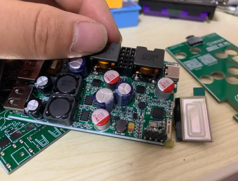
Hardware Selection
Hardware selection:
- The hardware for this project was purchased from Taobao. Although there may be fakes, I have never had any problems. You can choose as you see fit.
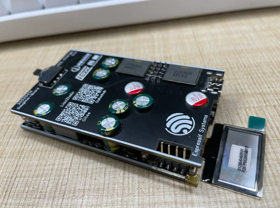
- The project uses Espressif ESP32C3FN4 chip as the control MCU, which has Wifi and Bluetooth. It is cheap and powerful, and can be used for secondary development to add many other functions (built-in 4M FLASH).
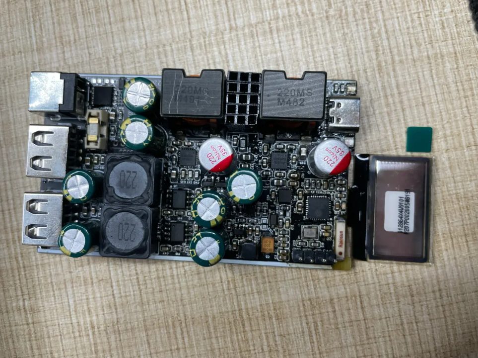
- The C-port power level uses the Zhirong SW3526 power chip (currently priced at 4.5 yuan per piece 😍). The chip supports multiple fast charging protocols. The power tube is integrated inside the chip to reduce the PCB area. The maximum power is 65W for a single channel. Two sets of channels are designed in this project.
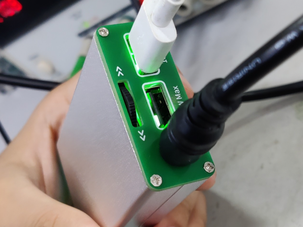
- The A port power level uses the IP6525T of Ingenic , which is cheap (currently priced at 1 yuan per piece 😍), with a maximum power of 18W per channel. Two channels are designed in this project, designed at the back of the fuselage, mainly to power fixed devices on the desktop, such as desk lamps, small servers, etc., and the switch can be remotely controlled by MOS tubes
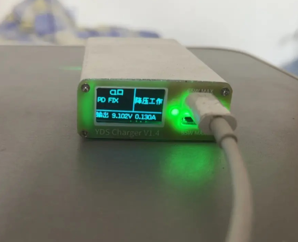
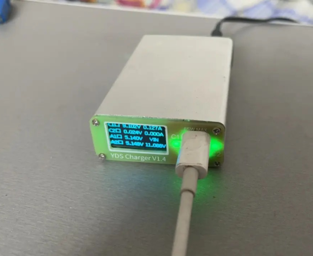
- The interactive interface display uses a 0.96- inch OLED screen (the size is just right, and the screen burn-in problem will be solved later by the screen saver).
- The input part is designed with a protection circuit, which has the function of anti-reverse connection (convenient for car charging applications), and the reverse connection system will not work. It has an overcurrent protection circuit (10A), and the overcurrent will blow the fuse. It has an anti-ignition slow start circuit to prevent electric sparks.
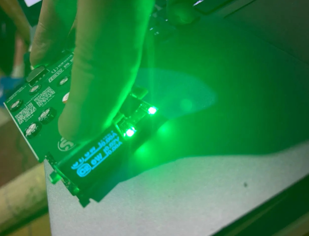
- The onboard four-way RGB indicator lights and panel can provide quick indication of the current system status.
- The acceleration sensor is LIS3DH , which can realize functions such as vibration control or somatosensory operation.
Project Parameters

- Input voltage: 10V-32V DC (it is recommended to use a replaced laptop charger, which is cheap and in large quantities. Of course, a 24V5A Delta power supply is more recommended to maximize power)
- Input power: >80W (144W at full load, but generally not fully loaded)
- Fast charging parameters are as follows:
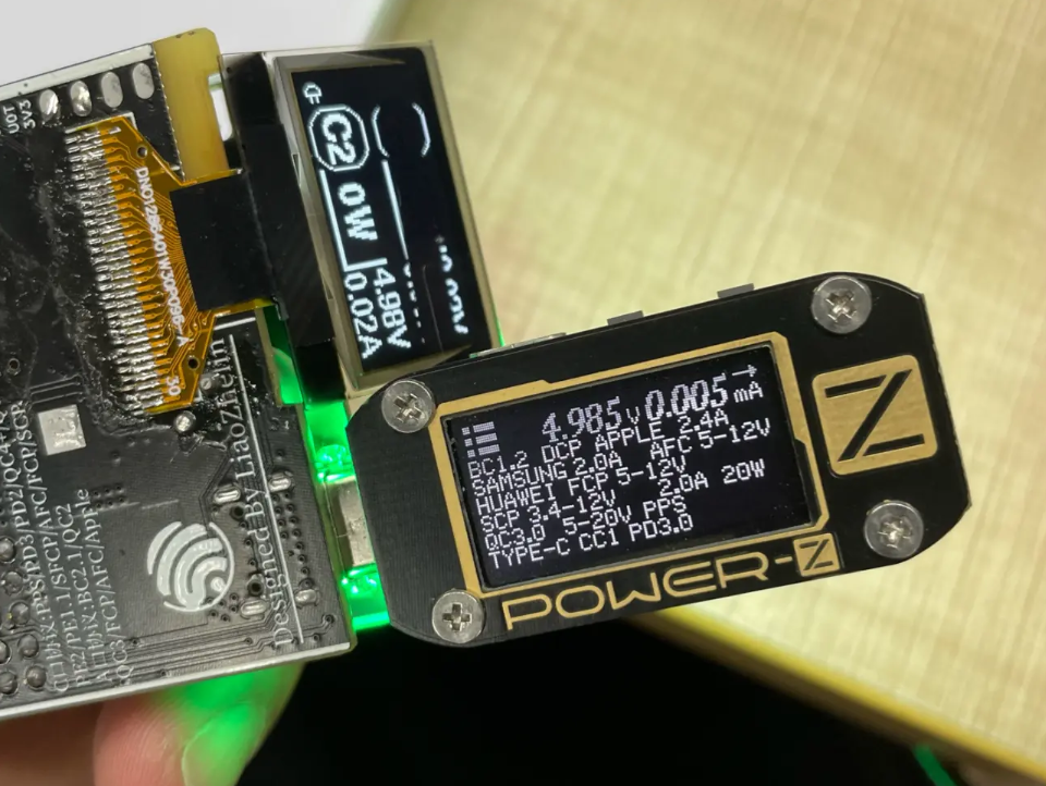
- C port output protocol: PPS/PD3.0/PD2.0/QC4+/QC4/QC3.0/QC2.0/AFC/FCP/SCP/PE2.0/PE1.1/SFCP/BC2.1/Apple/Samsung
- C port output voltage: 0.3-22V
- C port output current: 0-3.3A
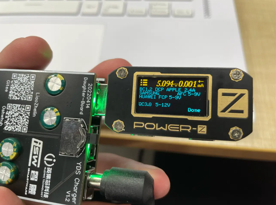
- A port output protocol: DCP/QC2.0/QC3.0/FCP/AFC
- Output voltage of port A: 0.3-12V
- Output current of port A: 0-3A
- PCB parameters: 47*80 (mm) thickness 1.6mm four-layer board
- Overall size (including shell): 50X 20X 80 (mm)
Production Notes
- After the product is welded and tested for short circuit and cold soldering, it can be connected to the computer through the download port USB and used after burning the program (ESP32C3 comes with internal USB and JTAG, which is very convenient). If it is not recognized, you may need to download the C3 driver and install it yourself.
- Please pay attention to the heat dissipation of the power stage during installation. It is recommended to place a heat conductive sheet on the back of the power stage to enhance the heat dissipation capability.
- Steel mesh welding is recommended for welding. In this project, all devices are arranged on one side, which can quickly achieve low-cost reflow soldering.
- When powered on for the first time, it is recommended to use a 5V power supply. Only after measuring that the RY8411 output is normally 3.3V, can the voltage be increased for subsequent tests.
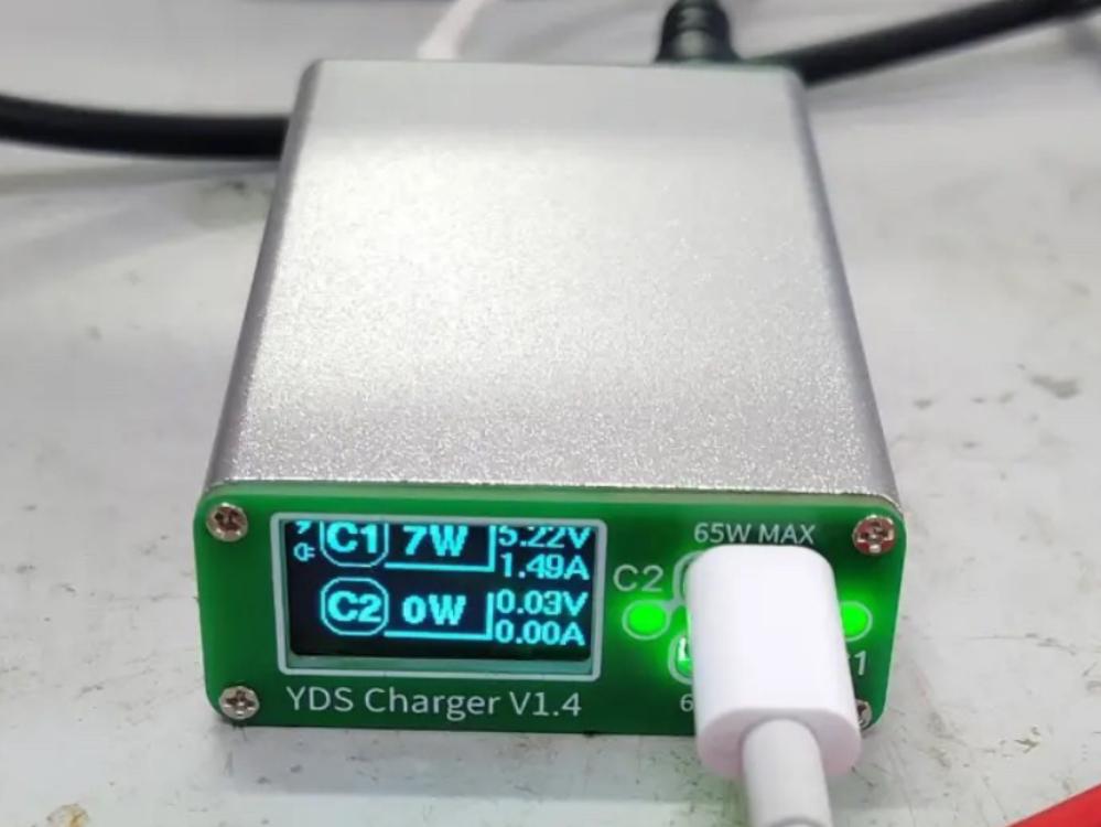
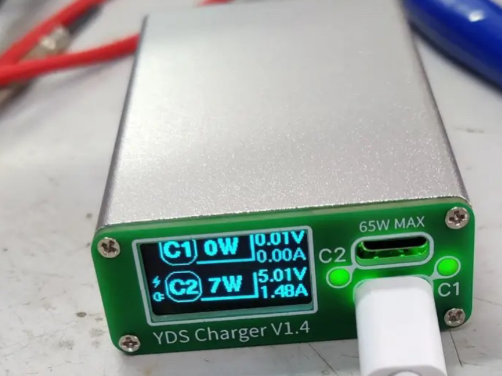
- Port C1 is on-board, and port C2 is brought out on the upper board through a pin header.
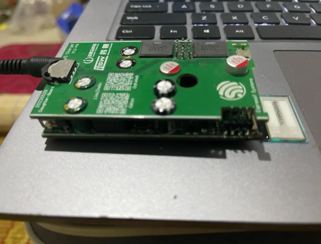
- The upper and lower boards are assembled with conventional pin and female headers, but the pin headers need special treatment , remove the plastic part and weld directly, otherwise the height between the slots is not enough:
- first stepStep 2third stepthe fourth stepthe fifth step
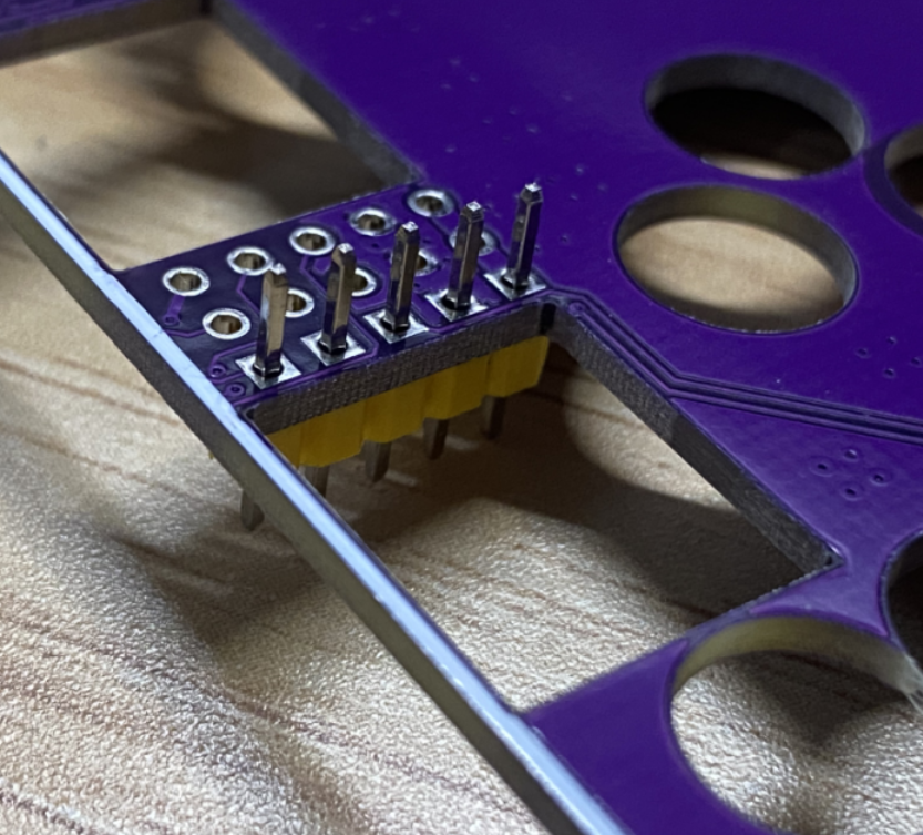
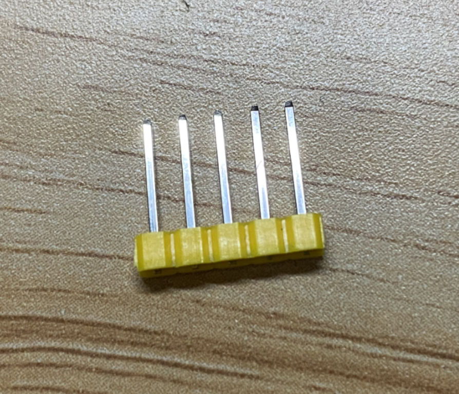
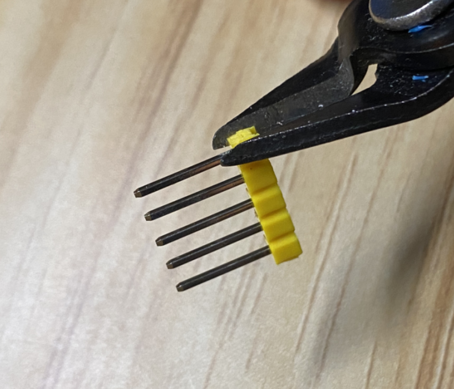
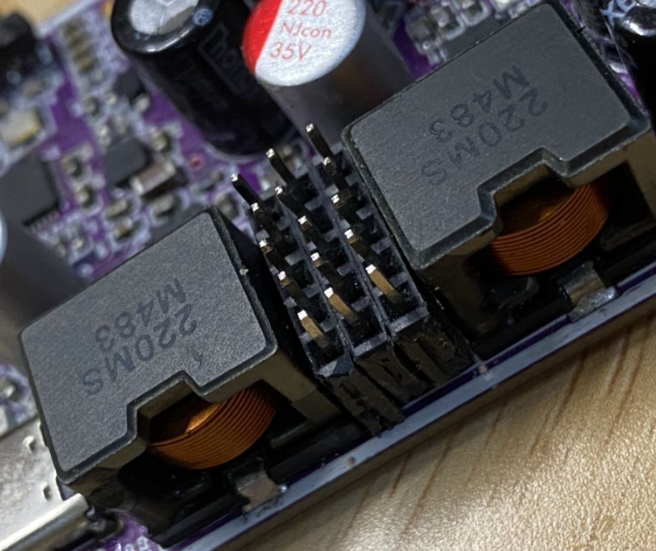
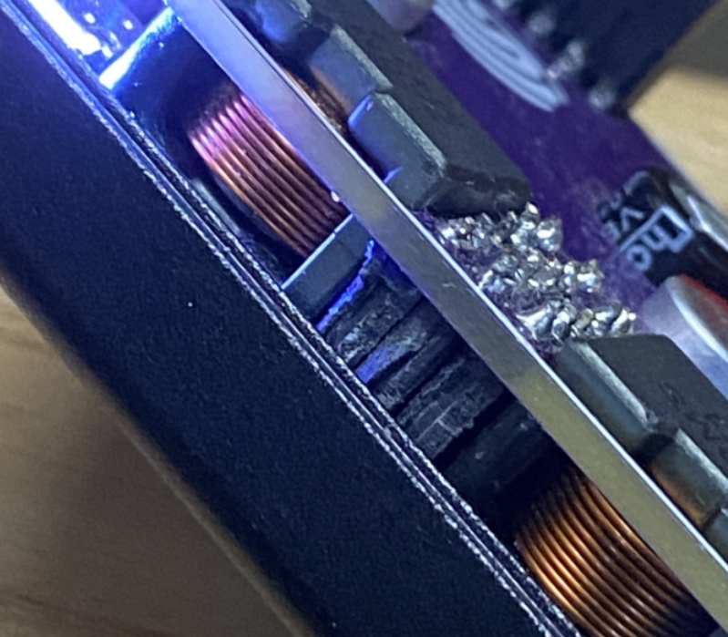 Insert the pin header into the upper board, place it on the table, and press downAfter taking it out, you can get the above needle arrangement. Make three sets according to this pattern.Use water pliers to remove the plastic part and get the pinsInsert the pin header into the welded female header on the lower boardPut the upper and lower boards close together, insert the pins into the holes, and then solder them. This distance is just the distance between the two slots.
After welding the upper plate, you can stick black tape on the corresponding position of the upper aluminum shell for insulation (you don’t have to stick it, there is actually a certain distance, just to be on the safe side.
Firmware Burning Tutorial
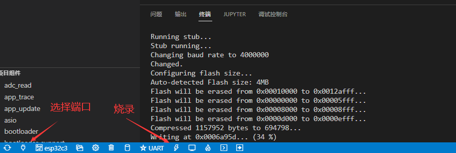
- Download via flash_download_tool_3.9.2 in the Fireware/tools folder
- This project does not provide PCB source files for the time being. The source code has been fully open sourced. Friends who need secondary development can modify it by themselves
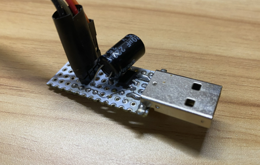
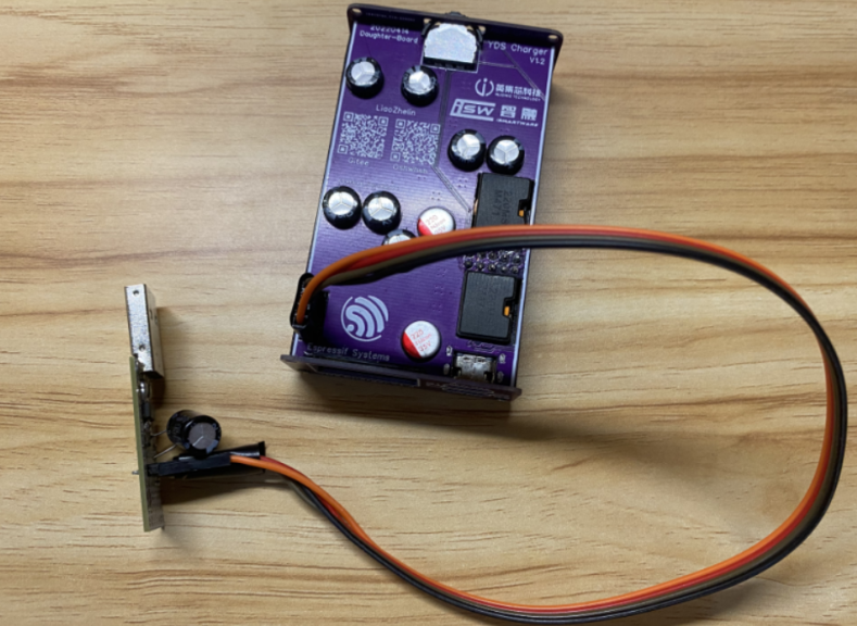
- This project does not require a burner/downloader. You only need a USB cable, but you need to solder a step-down circuit to convert the 5V of the USB port to 3.3V (or do not power it from the 3.3V pin header, but directly power it through the DC port). Do not connect the 5V to the 3.3V on the board, otherwise the ESP32 will be burned . I used a simple downloader with a perforated board + AMS1117 soldered:
- BurnerBurner connection board
- The merged firmware is located in Fireware/bin/target.bin, and the independent firmware is located in Software/yds_charger. It is recommended to use the merged bin download method if you do not plan to develop later.
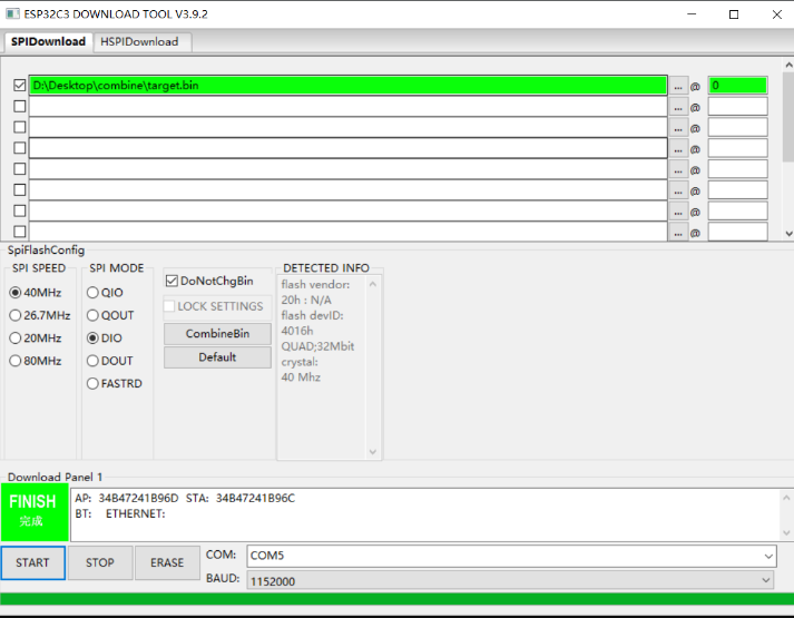
- After the software is opened, connect the device to the computer, 图1set the download mode as shown in the picture, and click OK.
- [Merge bin download method] Set up the software according to the picture below 图2 , click download and you should be able to download the firmware. You only need to burn one firmware in total, and set the address to 0
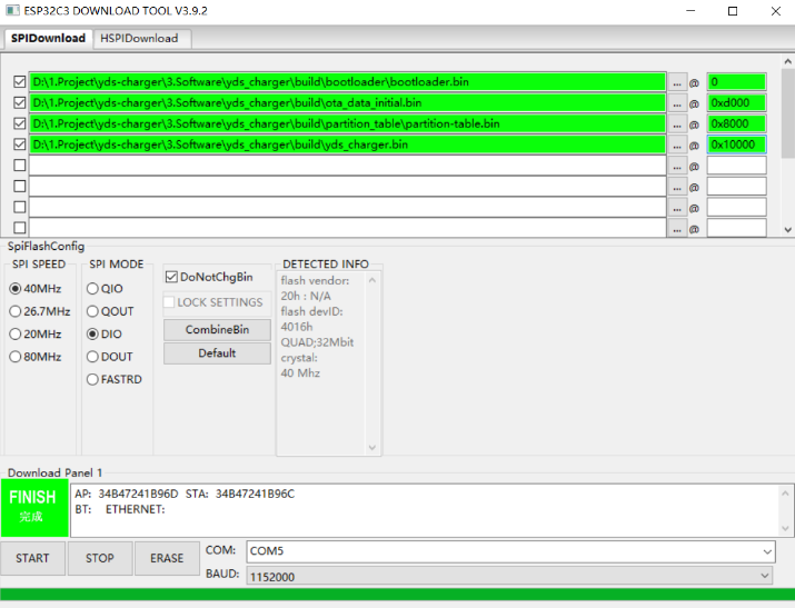
- 图3 [Independent bin download method] Set up the software according to the picture below , click download and you should be able to download the firmware. A total of four firmwares need to be burned, pay attention to the address setting
- If a connection error occurs, you can slide the toggle switch on the back of the upper board to the left (the side with the time number on the upper panel when viewed from the front), hold it , and then power on to enter Boot mode. After the burning is completed, turn off the power and then power on again, it should be able to be used normally.
After the burning is completed, power on and reset it, then it can be used.
figure 1figure 2image 3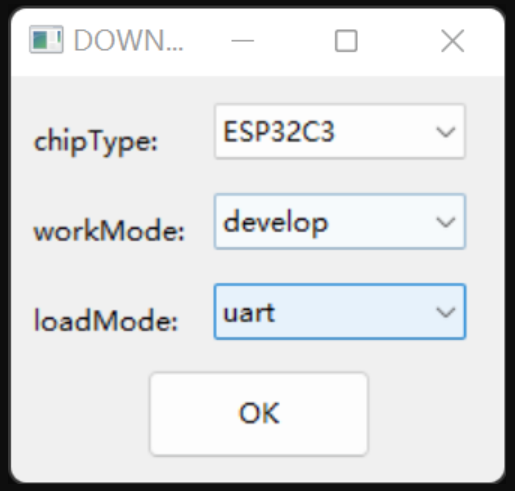
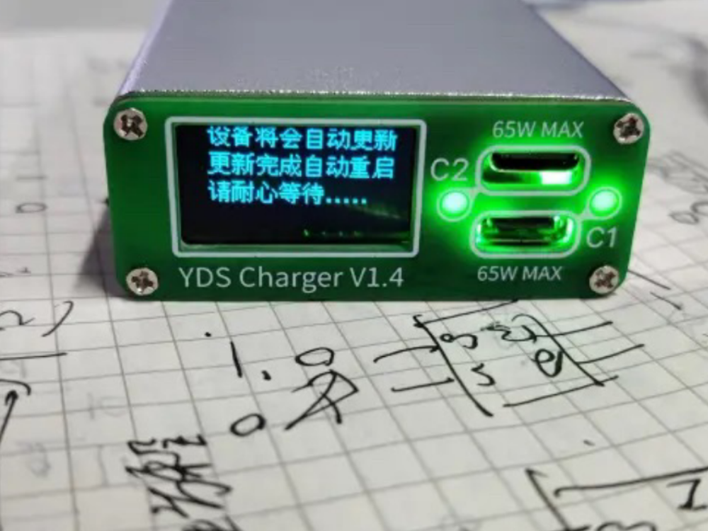
- OTA uses a ping-pong update partition of APP+OTA1+OTA2 (so that even if the power is cut off or the network is disconnected during the update, the device will not be bricked). After the initial burning and subsequent cover is closed, wireless updates can be used subsequently.
IDF Development
Development Environment Construction
- IDF development environment is developed in Python virtual environment in Windows system VScode+id. In fact, you can also build the development environment directly in Linux, or use it WSL+VScode. You can choose according to your needs. For detailed construction steps, see the official website construction process :
- Let's take my VScode+id build environment as an example:
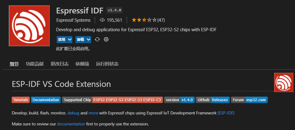
- Install Vscode, just download and install it, then search for the keyword Espressif IDF in the application market on the left and install it:
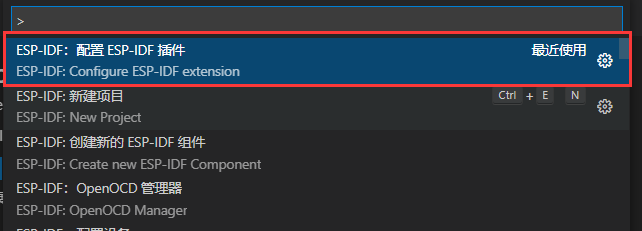
- After the plug-in is installed, press F1, find the option in the command Configure ESP-IDF extensionand click:
- Select ADVANCED mode to configure some options in detail:
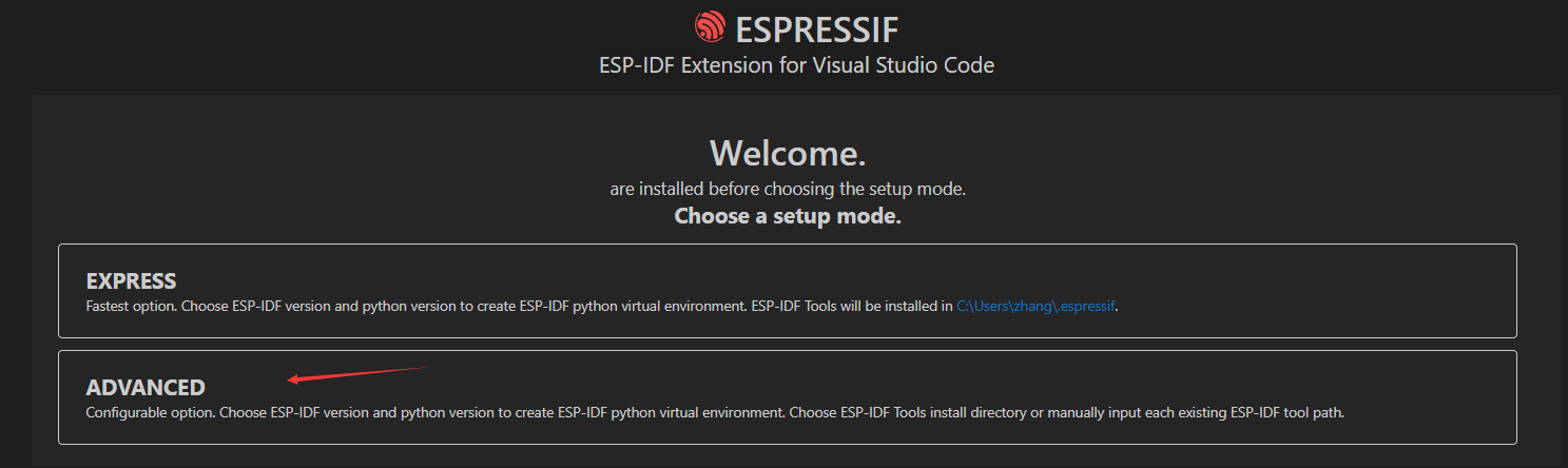
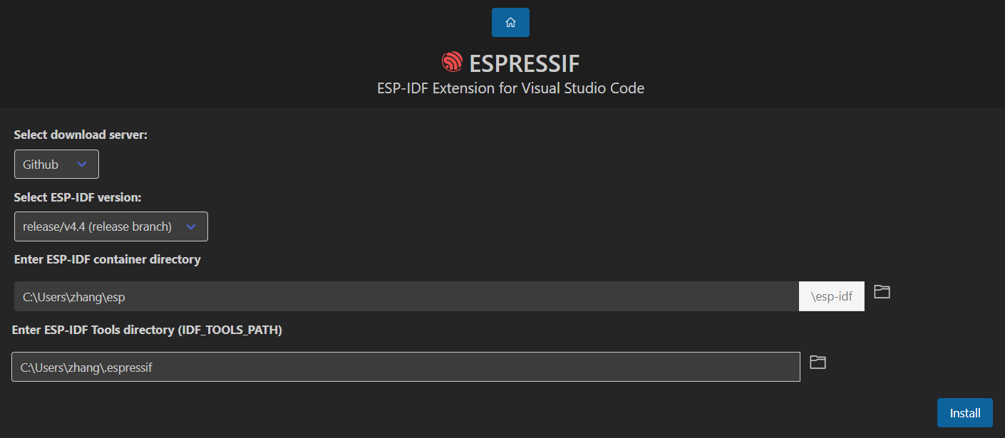
- Set the software source, IDF version, IDF path, and IDF tool path in sequence. If you are a scientific software source, you can directly select Github. If you are not a scientific software source, you can choose the domestic source of Espressif. Select the IDF version here release/4.4, and the other two can be set according to your own needs (do not use Chinese characters or spaces in the path). It is recommended to use the default path, and then click Installto install:
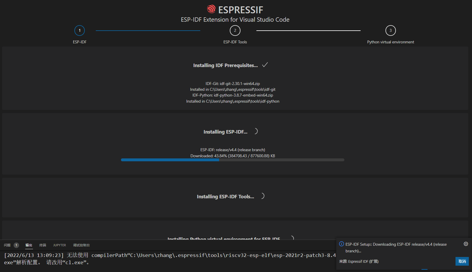
- Wait for ESP-IDF to be downloaded and installed. The overall size of IDF is not small, depending on the network speed:
- Next, install the ESP-IDF tool, which includes the virtual environment and some tool chains used in the virtual environment. Select Download ESP-IDF Toolsthe option and click Download Tools:
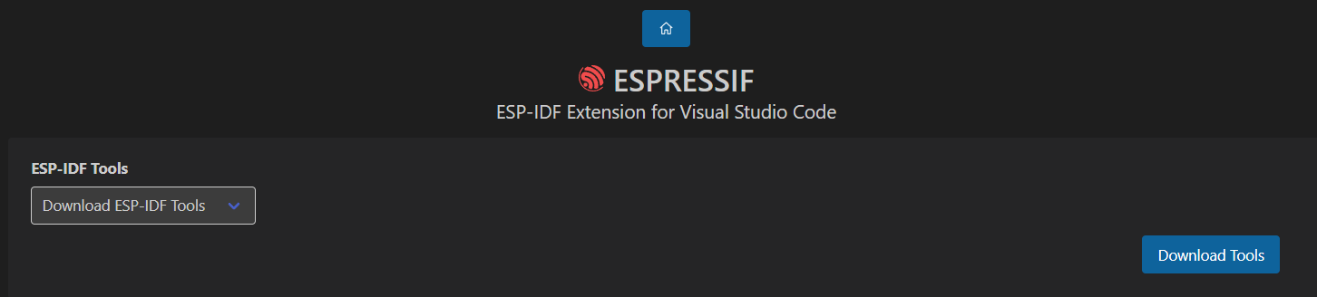
- Wait for the tool to install:
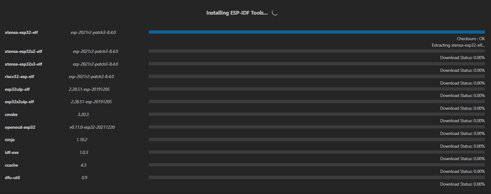
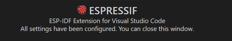
- If the following page appears, the installation is complete. If an error occurs in any of the above steps, it is usually a network problem:
Import engineering development
The project of this project is Software/yds_chargerunder , clone the project to the local, and mainly modify the .vscode folder in the project. The files in this folder control the functions of the IDF plug-in and the code highlighting prompt jump of Vscode itself.
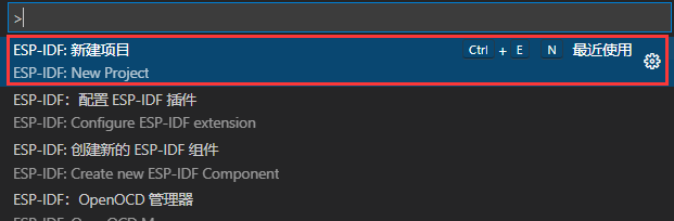
First verify whether the installation environment can be used normally, press F1, find in the command New Project, and click:
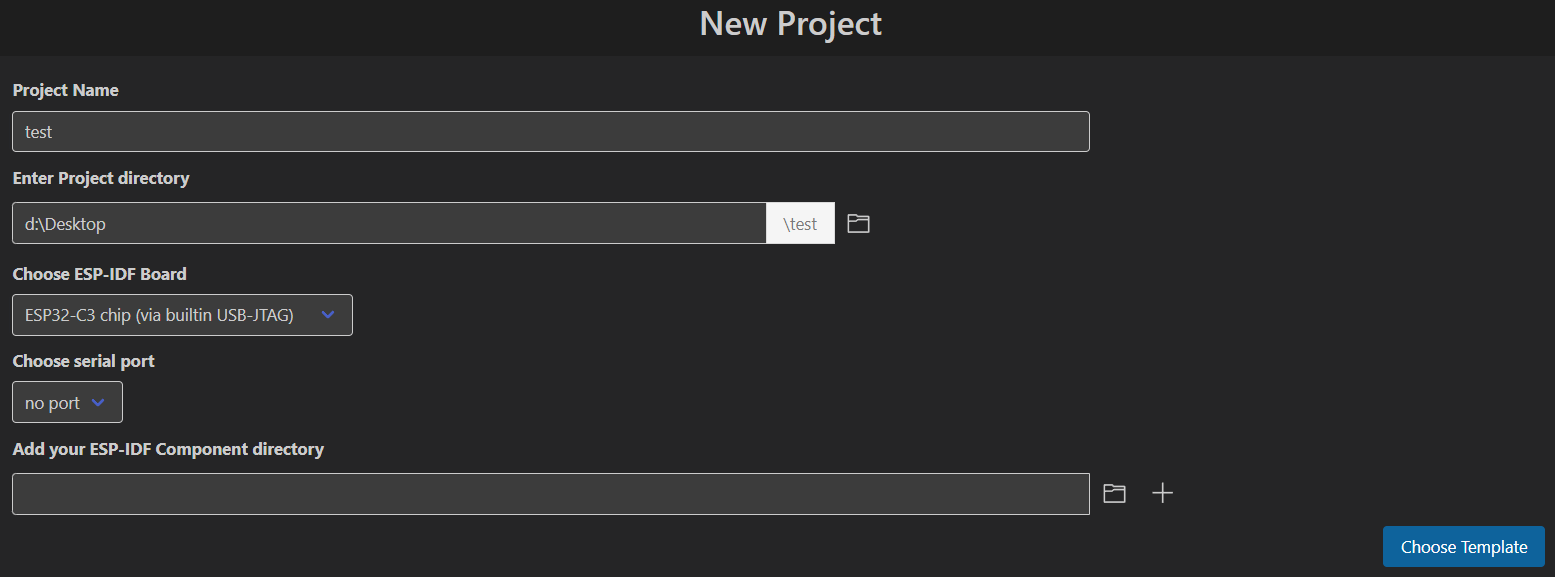
Modify the project name, path, board, and serial port according to your preferences (you don’t need to select it if it is not connected to a computer). You can ignore the last option and click Chose Template:
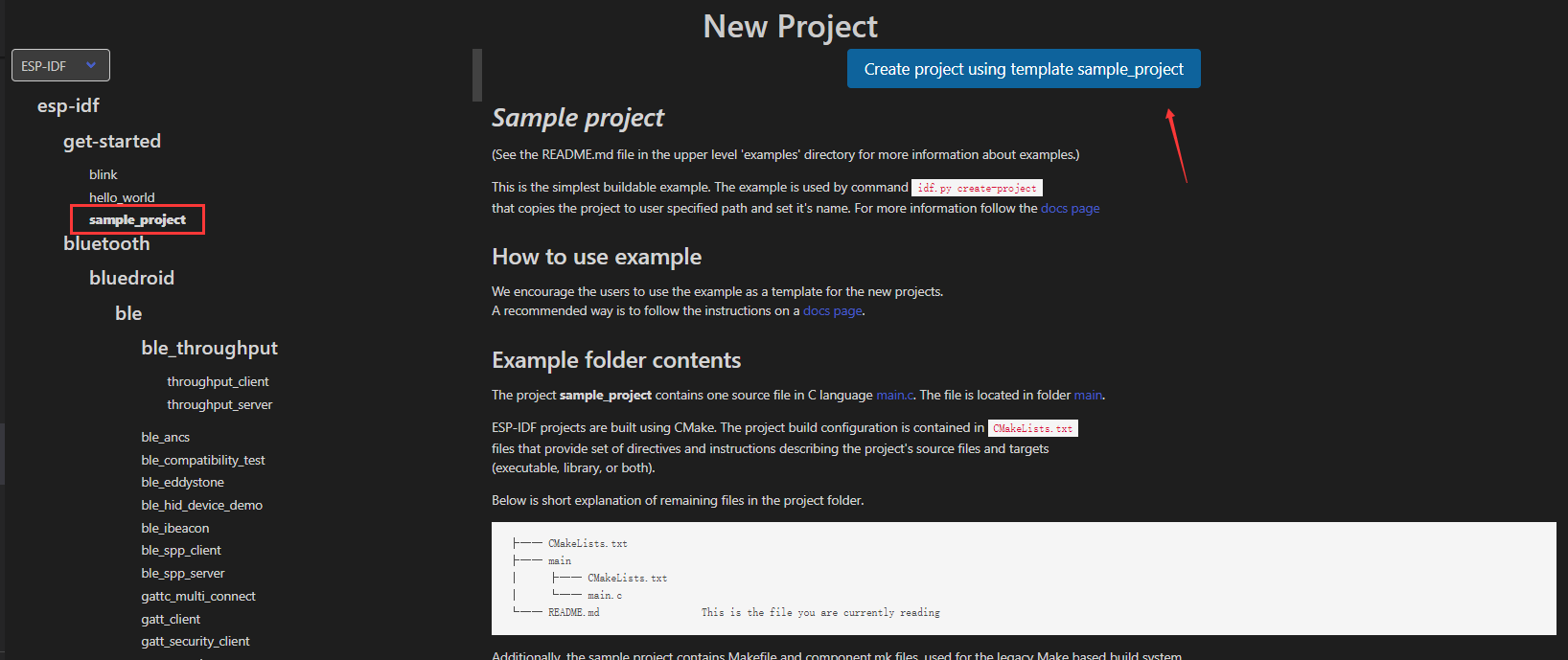
Select from the drop-down box ESP-IDF. Here you can select a simplest project to test. sample_projectAfter selecting, click the blue button to generate the project, trust the author in the folder and enable all functions:
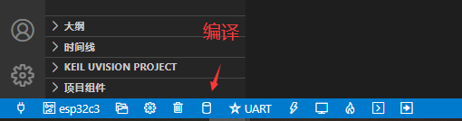
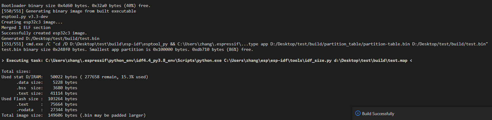
Click the compile button in the box below the project and wait for the compilation to complete. If the bin file can be successfully generated, the environment is successfully built (if the compilation is very slow, turning off Windows virus protection can greatly increase the compilation speed):
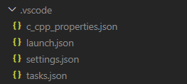
After verifying the compilation environment, you can copy the .vscode files in the sample project to the cloned project, or use F1the add .vscode file command in . It should contain the following four files:
You can develop happily later. Burning and downloading are also done with the following buttons, so I won’t go into details here:
Function development (updated on 22-5-27):
✅ Already developed 🚩Under development ❌Not yet developed or abandoned
Design featuresstateillustrateRemote network upgrade (OTA)✅With firmware version number verificationWIFI network configuration✅Network configuration via ESPTouch softwareMain interface display✅The standby and hibernation screen saver needs to be improvedFast charging protocol analysis✅ImplementedRGB Indicator✅Already implemented, control logic to be improvedVoltage and current monitoring of each port✅ImplementedOvercurrent and reverse connection protection✅To achieve, verifiedRemote control charger four-port switch🚩The hardware has been verified, but the logic has not yet been writtenAccelerometer (gravity sensor)🚩The program has been driven, but the function has not been written yetC port power limit🚩The program has been implemented, but the interface has not been added yetOTA automatic detection version upgrade🚩Version verification has been completed, json parsing is still being modifiedComputer CPU usage, memory usage display❌Not yet developedWeather display❌Not yet developedNumber of fans displayed❌Not yet developedGravity Rotating Screen❌Not yet developedBluetooth broadcast detection bracelet automatic power on and off❌Not yet developed
This project is prohibited from commercial use and is only for reproduction by enthusiasts. When making a project, please make sure that the hardware is fault-free before connecting the device for use (I have been using it for two months and there have been no problems so far. I don’t have many devices on hand, so the test may not be very complete and I cannot guarantee that there are no hidden problems in the system. I hope everyone can find the problems and improve them together). I do not assume any responsibility for damage to high-value equipment or other related losses.
Altitude: < 2000 meters
Ambient humidity: ≤ 75% RH
Working environment: 0℃ - 50℃
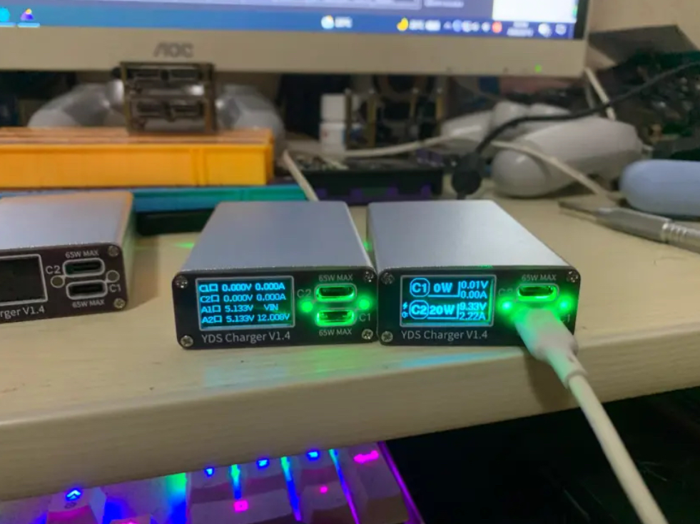
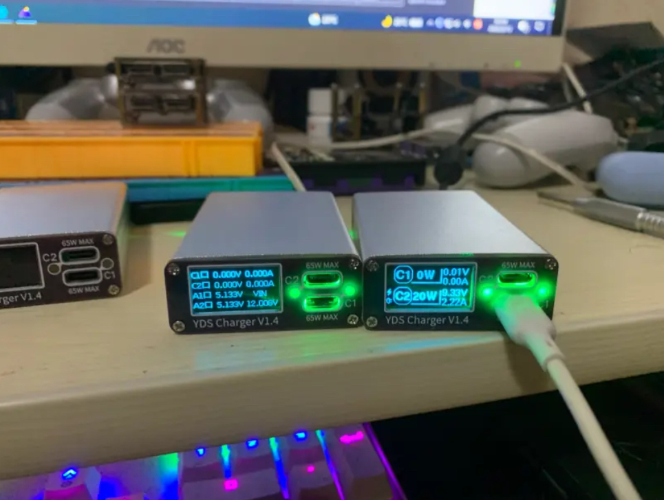
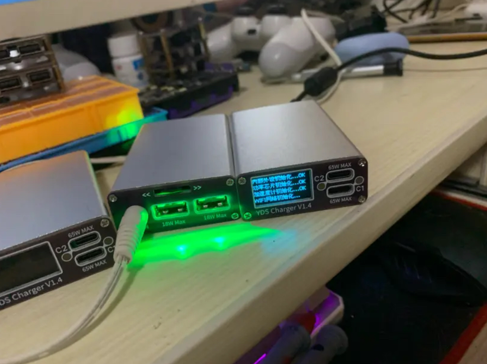
The finished products that the masters have successfully reproduced (each table is the finished product of the same author):
2022-6-13
2022-6-14
2022-6-16
2022-6-18
🙌If you have any questions, feel free to raise issues. Someone has successfully reproduced it.
......
Finally, let me commemorate the cannon fodder brothers in the development process. The first and third generations still have crooked holes == (a total of 5 versions were iterated, and 2 generations were moved and disassembled)