AM Radio Transmitter (Op Amp Based)
by nsamuel2 in Circuits > Electronics
3222 Views, 3 Favorites, 0 Comments
AM Radio Transmitter (Op Amp Based)

Link to video explanation of this project: https://drive.google.com/file/d/1xxkcVSy-g7SKOfbBBB7SrkqRLmrQ0SQB/view?usp=sharing
We are making an AM radio transmitter. AM stands for amplitude
modulation, which is simply the multiplication of two signals. In radio, there is a carrier
signal, usually in the 100kHZ to 100MHz range and the message signal which ranges
from 20Hz to 20kHz. Notice that the message signal frequency range is about the
range of human hearing. This is the signal that we want to send (music, someone’s
voice, etc.) By modulating these two signals, we get a signal that has the frequency of
the carrier signal and an amplitude that modulates with the frequency of the message
signal.
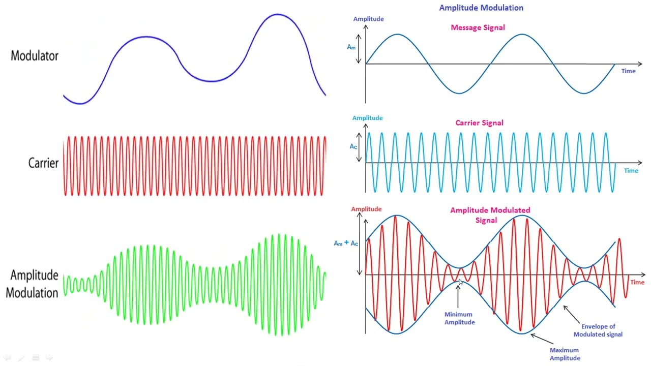
Example of amplitude modulation [1]
The circuit we will be making will work slightly differently. For the sake of simplicity, we are going to make a subtracting amplifier circuit whose input will be the carrier signal and the message signal. This shouldn't be an issue because the receiver is simply a low pass filter. Although the signal will not be symmetrical, it will still carry the appropriate information needed for the AM receiver to read the message signal. It may sound slightly different than real amplitude modulation but it should still work fairly well. It will subtract the message signal from the carrier signal which will look like this.
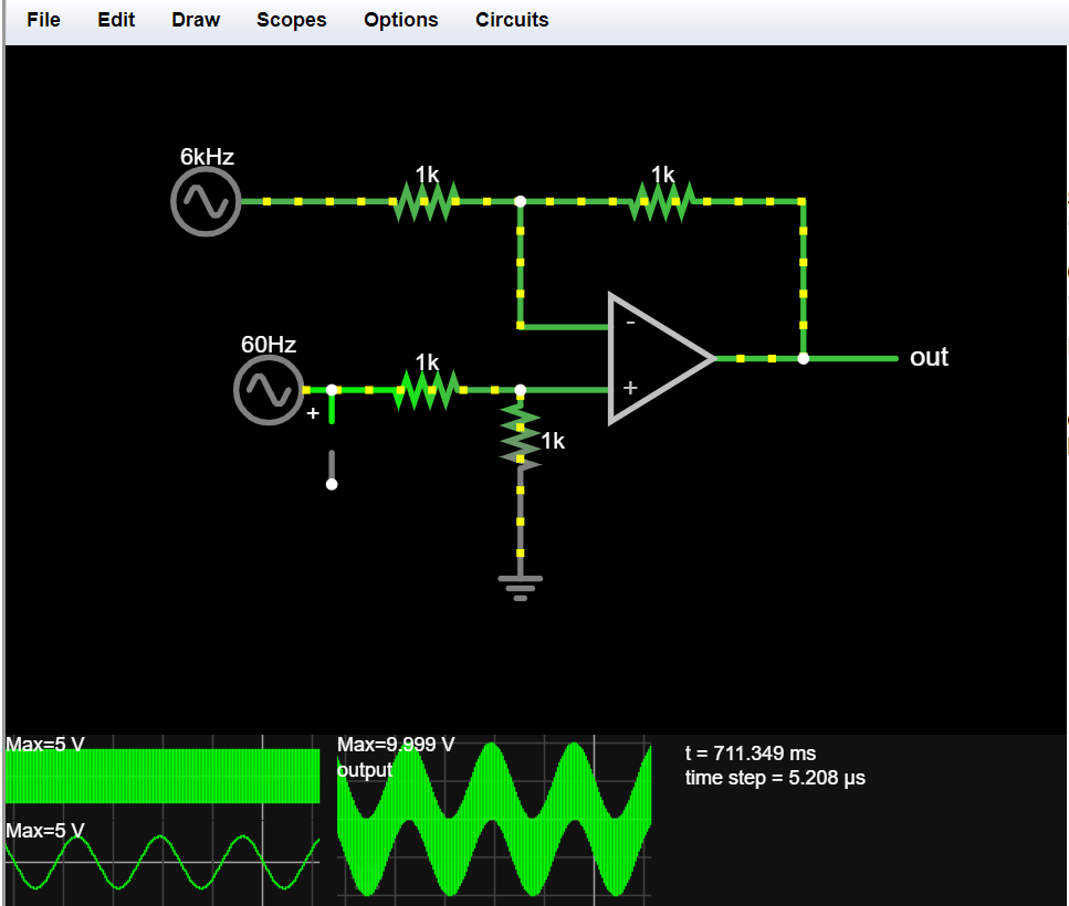
Our pseudo-amplitude modulation [2]
We can see that the signal still has the frequency of the carrier signal and the amplitude shape of the message signal. The next figure shows the difference between true amplitude modulation and our “subtraction” modulation that we use in the circuit. (Amplitude modulation on top and subtraction on the bottom).
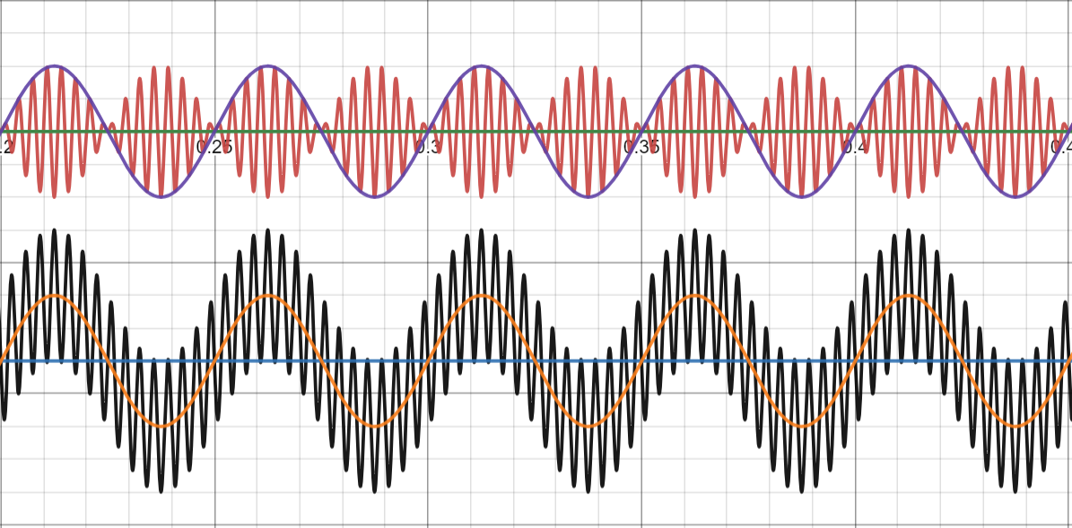
Similarities in amplitude modulation and “amplitude modulation” [3]
In building the circuit, the message signal should have about the same or greater amplitude than the carrier frequency signal. In order to achieve this, you may or may not need an initial amplification circuit to amplify the message signal. We included one to amplify our signal to about 5-10V. We are using a function generator to produce our carrier signal. If you use an oscillator, you may need amplification here as well. You can model this the same way as the message signal amplifier.
After the message signal amplification comes the subtracting of the two signals. All the components and equations will be detailed in the assembly instructions.
Supplies

Parts list:
- 2 x OPA551PA
- 5 x 1k resistors
- 1 x 10k resistor
- 1 solid wire 1.2m
- Wires to breadboard
- Function generator (or an oscillator circuit)
- Power supply
- Aux cord (audio signal)
- AM radio receiver (if you want to pick up your transmission)
Downloads
Assembly

Assembly Instructions:
First we’re going to assemble the message signal amplifier. We will use the OPA551PA
(datasheet in references below) for both amplifications in this project for its high slew rate and
bandwidth as we are dealing with high frequencies. We will use an inverting amplifier circuit
where the gain is the ratio of two resistors in the circuit.
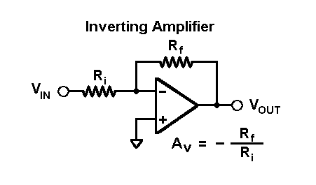
Inverting Amplifier [4]
We will be amplifying our signal by a factor of 10, where Rf = 10kΩ and Ri = 1kΩ. Our input will come from our audio signal. We used a computer and an aux cord that we stripped the wire to plug into our circuit. You should test this section of the circuit before moving onto the next part, checking that the Vpp is amplified by the appropriate amount. It is best to test multiple parts of the circuit as you make it to isolate and eliminate errors.
Next, we breadboard the subtracting amplifier that “modulates” the two signals. V1 in the picture below is our carrier frequency and V2 is the amplified message signal.
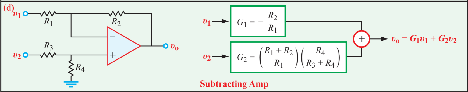
Subtracting Amplifier Equation and Subcircuit [5]
The value of all 4 resistors here is 1k because we only want the subtraction property of this circuit with a gain of 1 all the way through.
The Vout will contain our final amplified and modulated message and carrier signal. Here we use a length of wire that resonates with the frequency of the carrier signal. We are using a frequency of 1MHz, which has a wavelength of 300 meters. We can find this with this equation c = λ𝜐 (speed of light = wavelength*frequency). While it's not very feasible to have a length of 300m wire, we can cut this value in half repeatedly until we reach a reasonable number. This is about 1.2m for us. This causes the signal to resonate in our wire which makes for a clearer signal.
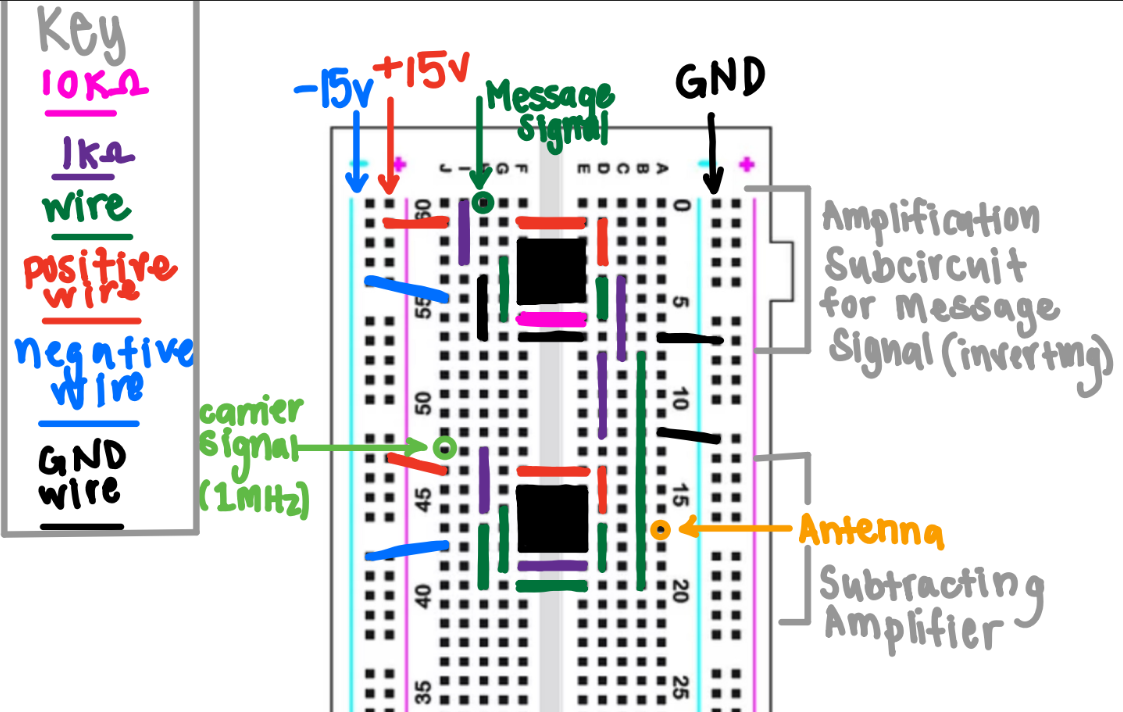
Our final circuit looks like this:
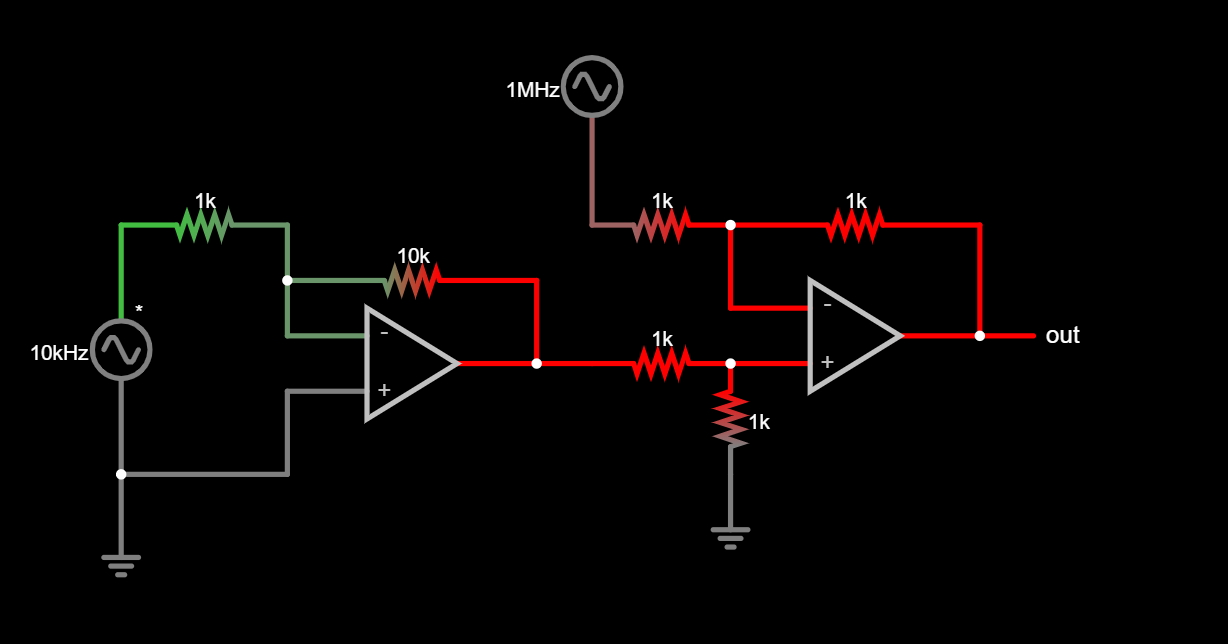
And our breadboarding looks like this: