AI Voice Activated Desk Lamp
by eighteen18 in Circuits > Arduino
4932 Views, 70 Favorites, 0 Comments
AI Voice Activated Desk Lamp


Welcome to this step-by-step guide on creating your very own AI-powered desk lamp!
This project combines modern technology with practical functionality, resulting in a smart desk lamp that responds to voice commands, touch inputs, and even reacts to music. Additionally, it features a weather station display and a wireless charger built into the base.
I started this project with the simple idea of creating a desk lamp using a normal LED bulb. However, with the help of AI (specifically, ChatGPT), the concept evolved into a much more sophisticated idea. ChatGPT suggested integrating voice recognition and touch controls into the project! Inspired by this new idea, I also decided to put a weather station display and a wireless charger inside the lamp which transformed it from a basic desk lamp into a smart and interactive accessory for any workspace!
Supplies


You will need quite a few things for this project:
- Arduino UNO: This will be the brains of our lamp.
- WS2812B LED strip - This will be our light source.
- 3x Touch sensors - This will manually control the lights.
- Elechouse Voice Recognition Module V3.1 - This will recognize our voice commands.
- Keystudio Microphone - This will be used to react to music/sounds.
- NodeMCU ESP8266 - To run the weather display.
- 0.96" OLED Display - To show the weather display.
- Wireless Charger Module - This will be used to charge any phone placed upon the base of the lamp.
- 2x LM2596 Voltage Regulators - This will control the power for the entire setup.
- USB-C Power Connecter Board - This will be used to provide power for the setup.
- 3D Printed Case - This will house everything.
- Power supply - I recommend something above 5V, 2A but below 35V. (Something like a 12V 5A power supply will work fine.)
- A bunch of wires - This project requires a lot of jumper wires and normal wires!
3D Printing


I designed the model in Fusion 360 and after some iterations, the model was perfect.
To begin, start by downloading the zip file attached. Then use a slicer such as Cura to print each model once.
I printed most of the parts with 10% infill and at a 0.28mm layer height in order to speed things up.
However, I would recommend printing the Arm.3mf model with around 40-50%+ infil and/or with 2+ walls in order to make sure it doesn't break under the weight of the LED housing!
Unfortunately, most of the parts will need supports, but I found that they were easy to remove and took less than 5 minutes to do so.
Disassembling the Wireless Charger


Since the wireless charger we are using comes in its own casing, we have to remove it.
Begin by removing the small screws underneath the rubber stops. Then you can pry at the case to separate it into two pieces and access the wireless charging module. It may be held on by glue so be careful not to damage the coil.
After you've done that, place it in a safe spot for the next step.
Gluing Components


Now, attach the components to the 3D-printed housing using some hot glue.
There are a few places to put each of the main components.
Base:
Keyestudio Microphone: Glue it into the designated spot with the hole for the microphone itself. You can also attach some wires in advance to make it easier later on.
Wireless Charger: Glue it into the designated spot at the front of the case.
Arm Post:
Touch Sensor: Glue all three of them into the space provided, making sure they are not too close to one another.
OLED Display: Glue the OLED display into the square hole at the base of the arm post.
Base Cover:
USB-C Power Port: Connect the USB-C port to a USB-C cable through the Base hole. Afterwards, place the Base Cover underneath the USB-C Port and use some glue to secure it in place. This will leave the USB-C Port hanging slightly off the Base Cover but it's going to have a secure fit with the USB-C cable.
LED Cover:
Voice Recognition Module- Place the microphone through the LED cover and then use glue to secure it in place.
LED Housing:
LED Strip - Using the provided M3 tape on the LED strip, glue it inside the LED housing.
Assembling 3D Printed Parts


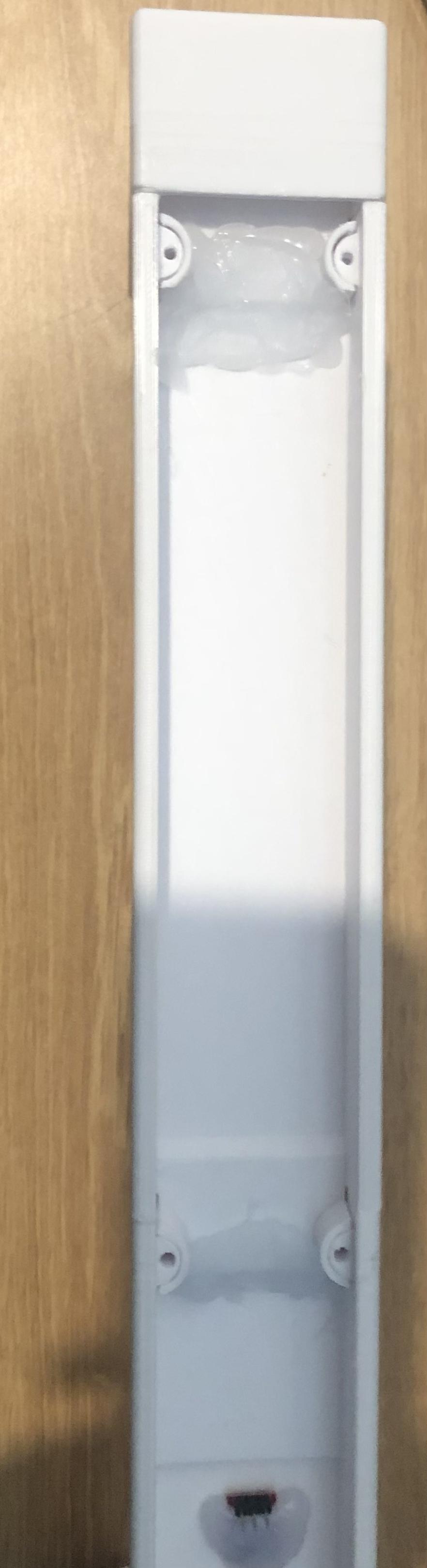


Now, to assemble the 3D-printed parts.
Place the Arm Post through the gap in the Base. Use glue to secure it.
Then, attach and glue the Arm Extender onto the Arm Post.
Afterwards, attach the Arm to the Arm Extender and use LOTS of glue to secure and strengthen it in place.
Finally, attach the LED Housing and the Arm together, using glue to secure them in place.
Adjusting Voltage Regulators

Placing the Lamp aside, we will need to adjust the voltage regulators to 5V in order to safely power the system.
To begin, use a multimeter and connect the voltage regulators to your power source.
Measuring the voltage, adjust the trimpot on the LM2596 in order to output a stable 5V. This step is crucial to prevent permanent damage to the components.
Programming Arduino and NodeMCU


Now we will need to program the boards.
NodeMCU:
The code running on the NodeMCU will be the ThingPulse ESP8266 Weather Station.
Begin by installing the following libraries:
- ESP8266 Weather Station
- JSON Streaming Parser by Daniel Eichhorn
- ESP8266 OLED Driver for SSD1306 display by Daniel Eichhorn. Use Version 3.0.0 or higher!
Then, prepare an OpenWeatherMap key using this tutorial.
Afterwards, in the Arduino IDE go to File > Examples > ESP8266 Weather Station > Weather Station Demo.
In the provided code, enter your OpenWeatherMap API Key, WiFi credentials and adjust your location according to OpenWeatherMap API, e.g. Zurich, CH.
Then, connect your NodeMCU up and hit upload!
Arduino UNO:
Training the Voice Recognition Module:
The training process of the Voice Recognition module is quite simple once you get the hang of it.
While it's too lengthy to get into in this tutorial, this video has a great demonstration of how to properly train and use it. Watch the video in order to find out how to train the model and then create 6 training indexes.
They should be named like so:
- Index 0, Light On: I used the phrase "Turn On" for this.
- Index 1, LightOff: I used the phrase "Power Off" for this.
- Index 2, ClapToggle: I clapped into the microphone for this.
- Index 3, MusicMode: I used the phrase "Music Mode" for this.
- Index 4, BrightnessUp: I used the phrase "Up" for this.
- Index 5, BrightnessDown: I used the phrase "Down" for this.
You can change each model to your liking but make sure that each index is assigned to the command you want, otherwise, you will need to change the AI_Lamp.ino code (more of that in a bit).
After you've finished training the Voice Recognition Module, it's time to upload the AI Lamp code into the UNO.
Begin by downloading the attached AI_Lamp.ino file. Since the code is fairly large and quite complex, I've decided to add lots of comments throughout the file so you can read them and understand what's going on! If you want to change any of the connections, you can modify the code to do so.
As for changing the voice command index, scroll down until you see //Voice Commands Index (line 37) and below it, you will be able to change the index number and name assigned to each command!
Now, connect your Arduino UNO and hit upload!
Downloads
Wiring


Now, glue the boards onto the case and prepare for the wiring process!
Refer to the provided Fritzing diagram and carefully connect all the components. This includes the touch sensors, LEDs, voice recognition module, microphone, OLED display, voltage regulators, etc. Ensure each connection is secure and correct.
Downloads
Testing & Assembly
Before you screw in the Covers, apply power to the system through the USB-C port and verify that everything is working.
Make sure that everything is working including the voice commands, touch sensors, music-reactive lighting, weather display, and wireless charging!
Finally, once everything is tested and confirmed working, use some M3*12 screws to secure the Arm Cover 1, Arm Cover 2, LED Cover and Base Cover in place!
Final Showcase


Congratulations!
You have now successfully built an AI-powered desk lamp with advanced features!
This project shows how modern technology can be integrated into everyday objects to increase functionality. Through this Instructables, (hopefully) you've learned a thing or two about 3D printing, electronics assembly, programming and the uses of AI such as ChatGPT!
The use of ChatGPT played a significant role in this project. Not only did it provide me with tons of valuable suggestions and assistance in various aspects, including enhancing my initial idea of a basic desk lamp by adding advanced features like voice recognition, touch controls, and a weather display, but it also offered guidance on writing and troubleshooting code for the Arduino UNO and NodeMCU!
It even provided insight into my component selection and circuit design!
I hope this Instructables has inspired you to explore further possibilities in DIY electronics and smart devices. Enjoy using your new smart desk lamp, and feel free to customize and enhance it further to suit your needs and preferences. Happy making!