ESP32 and Blynk - Air Conditioner Control Centre
by hausofpayne17 in Circuits > Arduino
7505 Views, 1 Favorites, 0 Comments
ESP32 and Blynk - Air Conditioner Control Centre
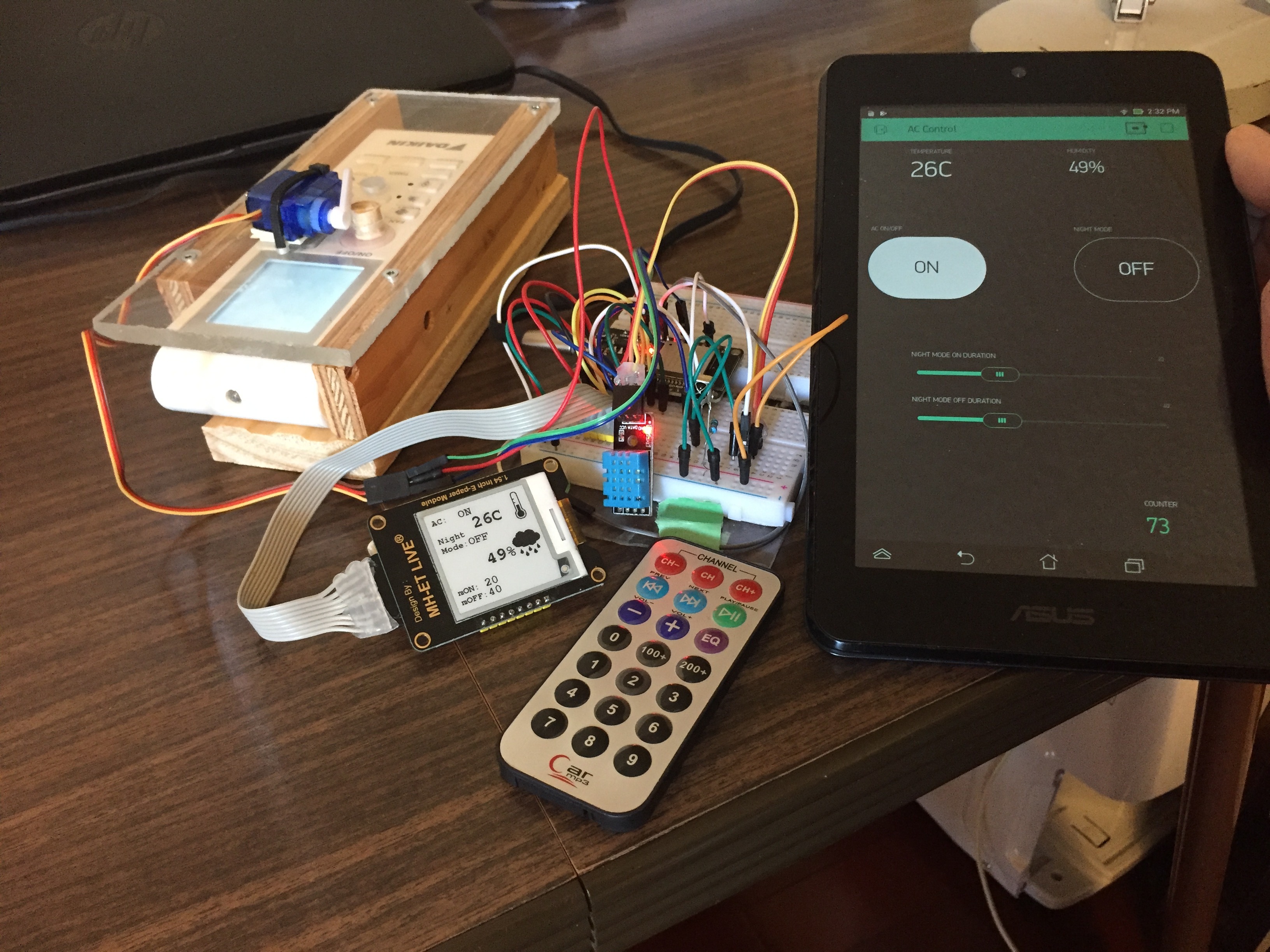
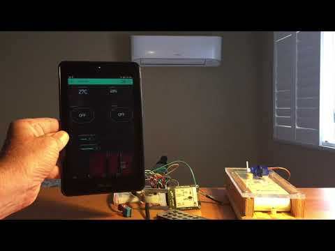
This is an introductory Internet of Things (IOT) tutorial.
We'll build an Air Conditioner Control Centre and web-enabled phone app using the following hardware/features:
- ESP32 Webserver
- ESP32 TouchPins
- ESP32 Servo Control
- Epaper Display
- DHT11 Temperature/Humidity Sensor
- Infrared Remote Control detection
- Blynk Internet of Things Communication and phone app design
I've got an air conditioner that has an infrared remote control. The unit works well but if you want the room temperature to be 22C, it will run until it reaches that temperature and then just turn off the compressor and keep the fan running 100% of the time. I find that annoying.
I want to be able to have the unit come on and run for a fixed number of minutes and then shut off for a fixed number of minutes and have the on/off cycle repeat throughout the night.
I've done it using an ESP32 Dev Board and I control it through a Blynk IOT phone app.
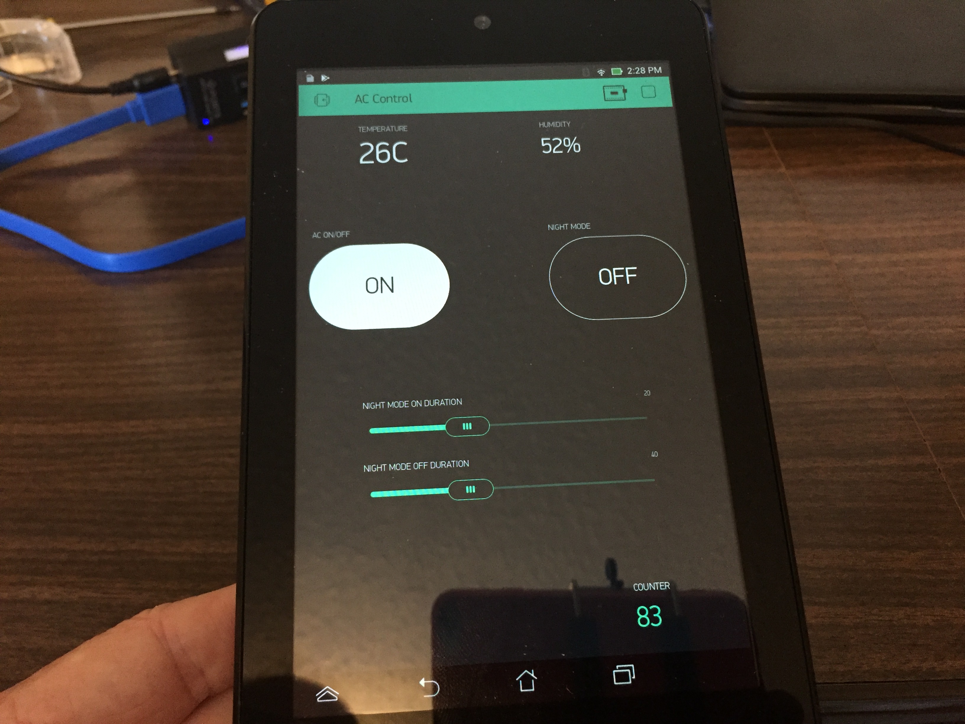
Now I can use my phone to see the current temperature and humidity in the room and turn the unit off or on remotely. I can also activate 'Night Mode' from the phone to turn on the on/off cycle to keep the room comfortable at night.
As the ac unit's remote control is in a housing so it can be activated by a servo, I am using a second remote control that I can keep by the bed to quickly turn the unit off/on as desired. It's faster than logging into the phone.
This is a great introduction to using the ESP32 with an ePaper display, infrared remote, and the Blynk IOT infrastructure to easily create a phone app to control the project.
Let's get started!
Supplies
Air Conditioner with Remote Control (well YES! Obviously!)
ESP32 Development Board
ePaper display (1.54") (Waveshare, MH-ET, Adafruit etc)
Servo
DHT11 Temperature/Humidity module
DS1838 Infrared Receiver
100R resistor - limits current to the DS1838 which will be damaged by the high current from the ESP32.
Infrared Remote Control
Breadboard and wires.
Infrared Library - install from Arduino IDE
BLYNK Internet of Things Library - install from Arduino IDE
DHT Sensor Control - install from Arduino IDE
Adafruit Graphics Library - includes drawing primitives and fonts. Install from Arduino IDE
Gx_EPD2 Epaper Display Library - install from Arduino IDE
Plywood and plexiglass for the Remote Control/Servo housing.
Build the Remote Control Unit / Servo Housing
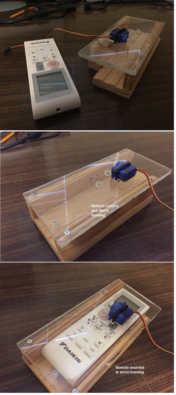
You should measure your AC unit's remote control's dimensions and then build an enclosure to hold it.
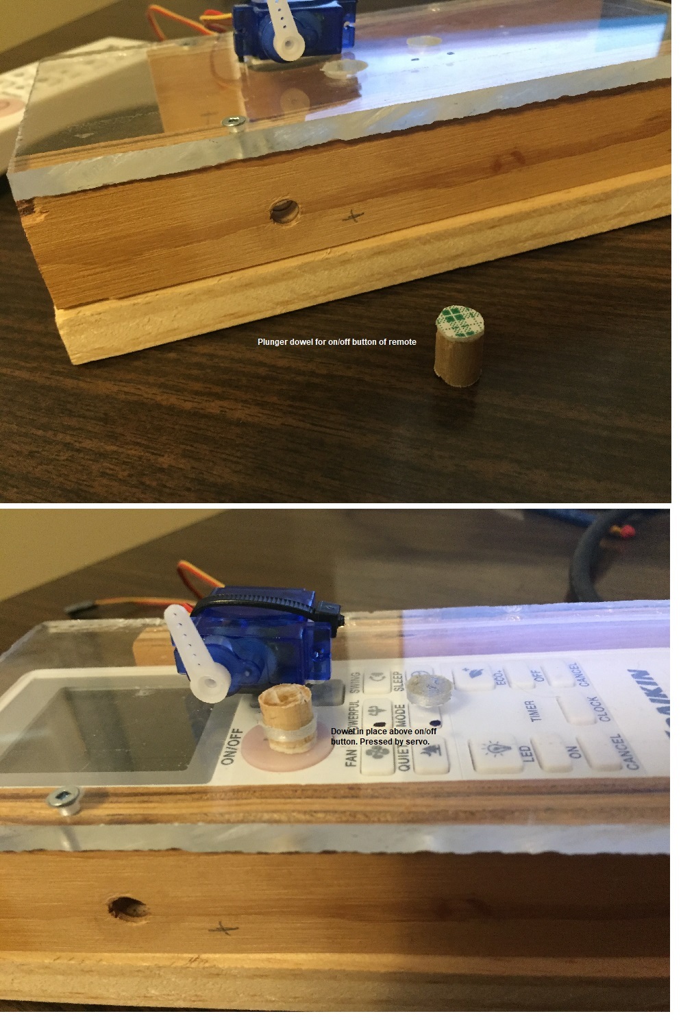
Mark the plexiglass to indicate the location of the On/Off button and drill out a 1/2" diameter hole.
You will use a short length of dowel that is pressed by the servo horn. It depresses the on/off button as needed. I used 1/2" hardwood dowel cut about 5/8" long with some foam tape placed on the end to press against the on/off button of the remote.
Look at the photos to see how the dowel activates the on/off button on the remote.
You'll want to adjust the servo settings in your Arduino code to allow the servo to cycle properly so that it presses the power button fully on activation. Make sure the servo doesn't press too hard as it may cause a voltage brown-out condition on the ESP32 and force a restart of the ESP32. This will be discussed further later in the instructable.
Building the Circuit
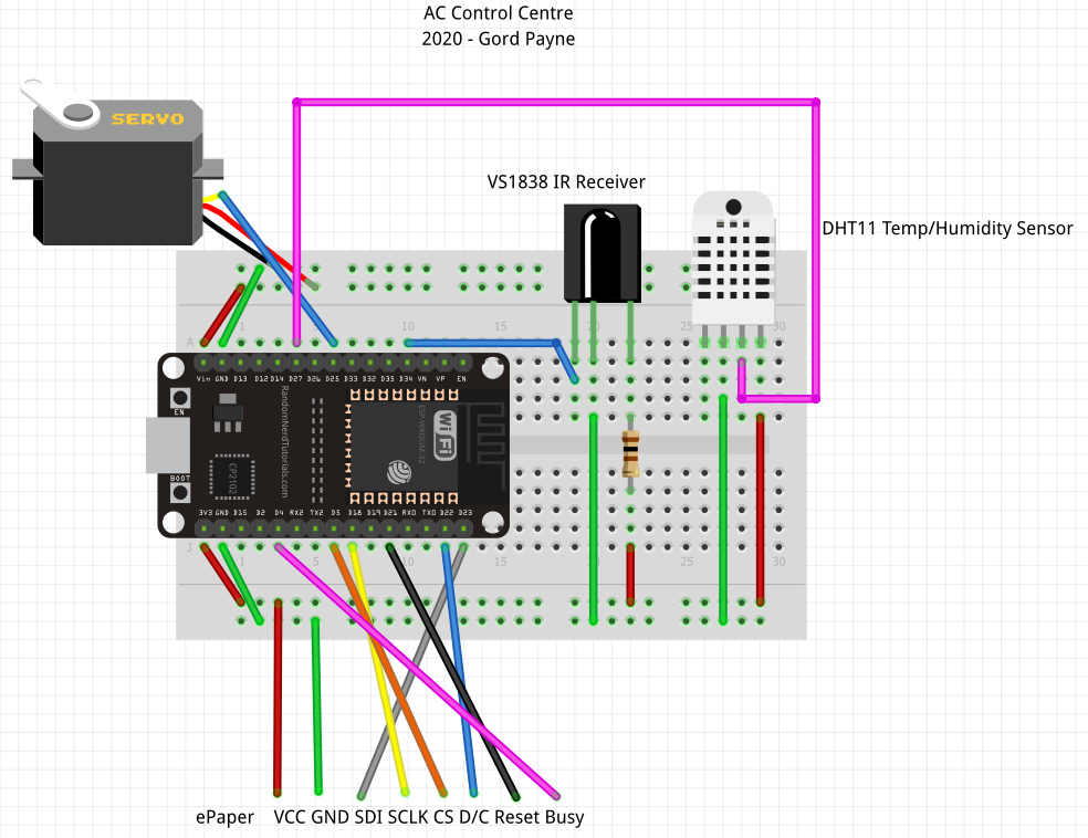
Build the circuit as specified in the wiring diagram.
Please make sure the power supply you'll be using for this project has sufficient current to supply both the ESP32 and the servo. 1 amp power supplies are typically suitable for this project.
Feel free to use different pins for your devices. However it's recommended that you use the pin specified for the e-paper display.
Double-check your wiring when finished.
Arduino Programming - Highlights
This instructable assumes you know how to do basic Arduino programming as well as adding libraries. The sketch is thoroughly commented so please read the sketch carefully. The icons.h file contains byte arrays for the two pictures on the e-paper display.
This project requires you to add the following to your Arduino IDE
ESP32 board definitions
Infrared Library - install from Arduino IDE
BLYNK Internet of Things Library - install from Arduino IDE
DHT Sensor Control - install from Arduino IDE Adafruit Graphics Library - includes drawing primitives and fonts. Install from Arduino IDE
Gx_EPD2 Epaper Display Library - install from Arduino IDE
Now let's look at some highlights of the programming in the following steps.
Arduino Programming - E-paper Display
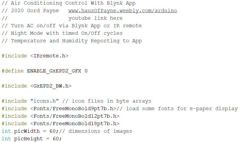
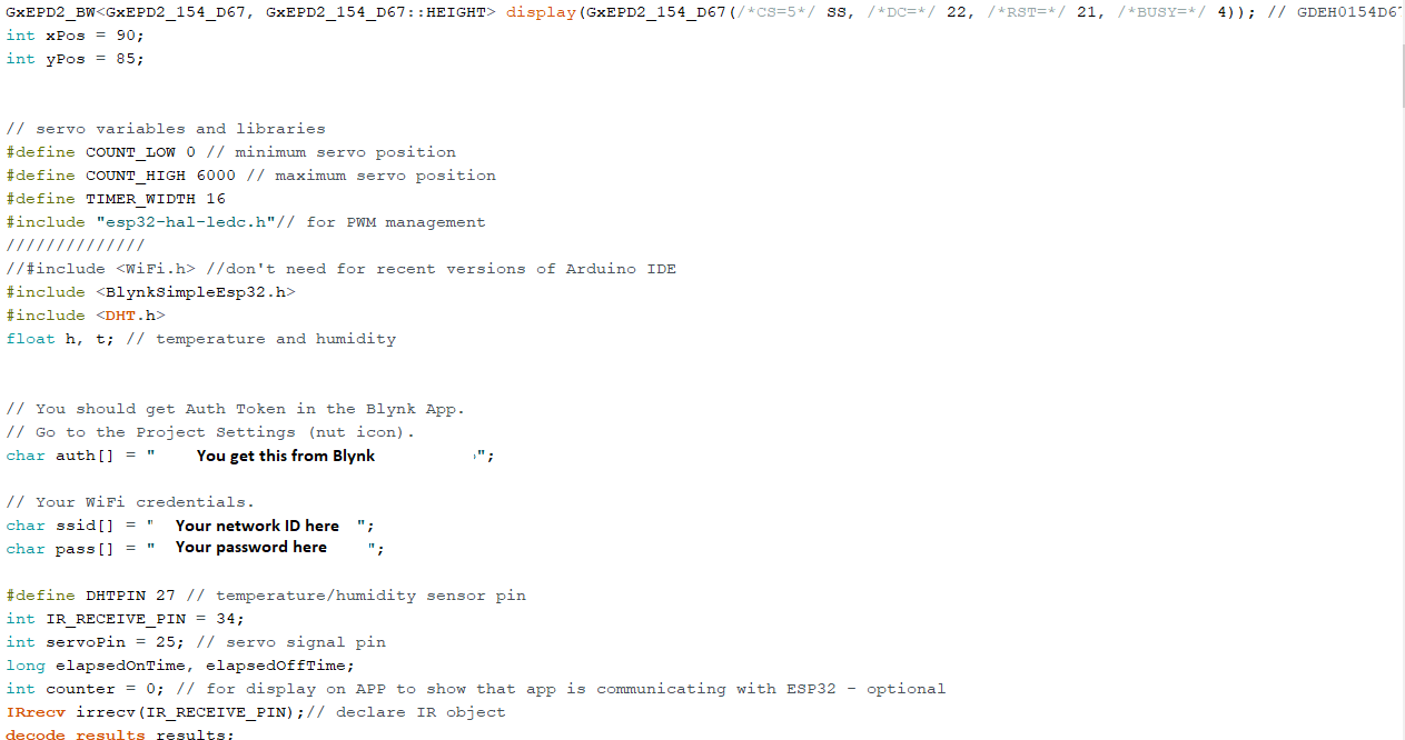
This E-paper displays take a bit of configuring. This project is based on the WaveShare 1.54" Black/White display.
In the first screen shot you'll see we define the GFX object for the display and we include the GXEPD2_BW library.
It is recommended that you explore some basic E-paper programming sketches from the Gx_EPD2 library that you loaded into your Arduino. The basic sketches will work well. Just make sure you're choosing Black/White display sketches.
In the second picture you'll see the definition of the display object.
The display is wired as follows:
Epaper Display ESP32
VCC ---------------- 3.3V
GND ---------------- GND
SDI ---------------- Pin 23
SCLK ---------------- Pin 18
CS ---------------- Pin 5
D/C ---------------- Pin 22
Reset ---------------- Pin 21
Busy ---------------- Pin 4
We define the object as follows:
GxEPD2_BW display(GxEPD2_154_D67(/*CS=5*/ SS, /*DC=*/ 22, /*RST=*/ 21, /*BUSY=*/ 4)); // GDEH0154D67
This definition creates an object called 'display' that is the reference for all display-related commands. This definition is specific to the 1.54" Black and white display, designated as GDEH0154D67. This definition is current as of July 29, 2020. If you're using a different display, you should use the appropriate definition for your display.
In this cimmand, you'll see the CS pin defined as pin 5, the DC pin is Pin 22, the Reset pin is 21 and the Busy pin is 4.
Arduino Programming - Servo, Blynk, Wifi, Infrared Setup
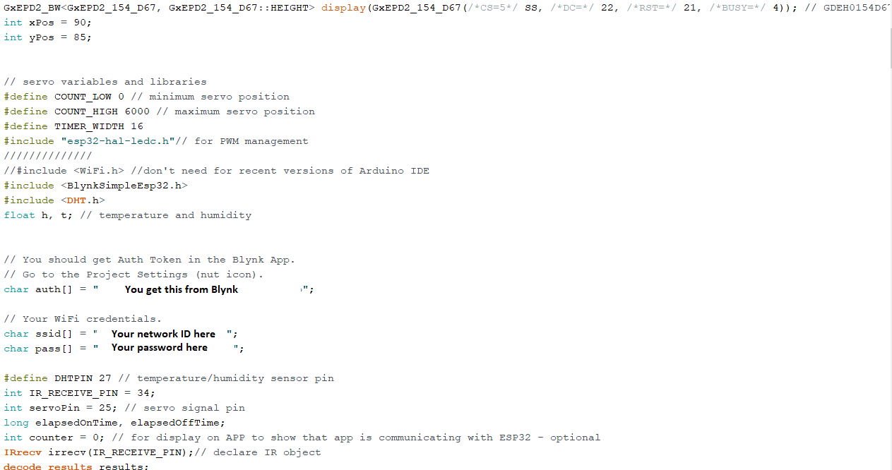
For controlling the servo, the servo library from Arduino does NOT work.
This sketch uses basic ESP32 pwm commands to control the servo
You'll see some servo minimum and maximum value definitions that pertain to the zero and maximum throw positions of the servo. You may want to modify the COUNT_HIGH value to suit your particular servo operation.
We include the Blynk and DHT libraries for internet-of-things communications and reading the DHT sensor.
We define a char array for our Blynk Authorization key. Once you design your Blynk app on your phone/device, you'll ask for an Authorization key. The value the app gives you will be entered in the auth[] array.
We define char arrays for the network name and your password.
Arduino - Defining Infrared Remote Codes

The supplementary remote control needs to be programmed.
The code in the loop() method allows you to read a code from the remote's button. You'll then use that code to detect that particular button being pressed.
Just put in a Serial.print() statement of the theVal variable in your code so you can see the codes that come across for the different buttons on the remote.
Arduino - Cycling the Servo
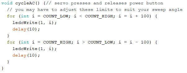
The cycleAC() method is called any time you program wants to cycle the servo to press the power on/off button on the air conditioner's remote. It's a standard servo cycling method.
Arduino - Reading and Updating Blynk Virtual Pins
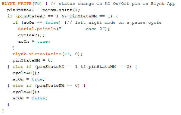
Developing a Blynk app is very straightforward however the tutorial would take a lot of time in this instructable. Please see this video for an excellent introduction to making a Blynk app for an ESP8266. It's identical for an ESP32.
Blynk creates 'Virtual' pins that you can send data to and read from.
In the Blynk phone app you create, you assign a virtual pin to each display object or control (button, slider etc)
Blynk defines BLYNK_WRITE(Vpin) methods to read the state of a virtual pin on the app.
You use the param.asInt() method to store the value of that pin in a variable in your Arduino sketch.
The Blynk.virtualWrite(pin,value); method let's you send a value to the app.
In this project, the virtual pins are defined as follows:
V0 - Air Conditioner On/Off button
V1 - Night Mode On/Off Button
V2 - Night Mode ON cycle Slider (duration in minutes)
V3 - Night Mode OFF cycle Slider (duration in minutes)
V5 - Temperature display V6 - Humidity display
V7 - counter ** This is optional. It's just a repeating counter that confirms to you visually that the app is communicating with the ESP32. You don't need it.
Once you're ready, upload the Arduino sketch to your ESP32.
Blynk - App Setup
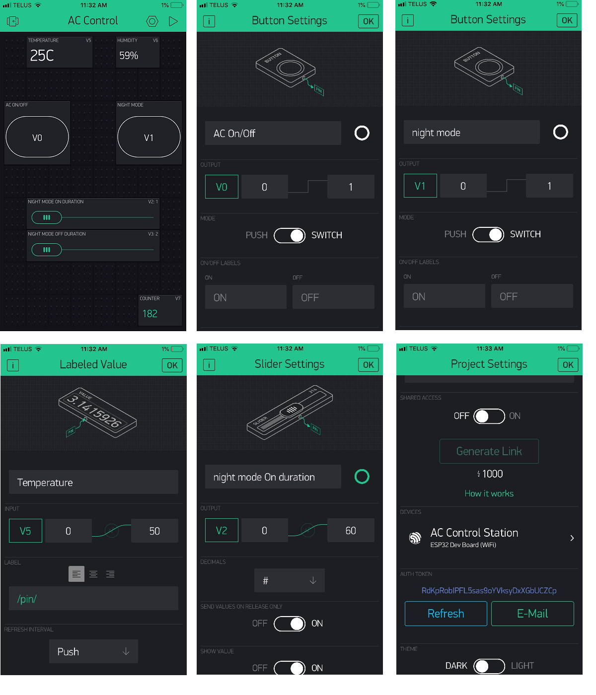
The photos give basic setup of each app screen display object or control. You may modify these as you wish.
Conclusions
This is a very involved project but it yields great results.
I hope you enjoyed building it and that it inspires you to work on other IOT projects.
Now Go and Make Something Wonderful!