A Weird Arduino Powered Clock
by electronics for everyone in Circuits > Arduino
15192 Views, 122 Favorites, 0 Comments
A Weird Arduino Powered Clock
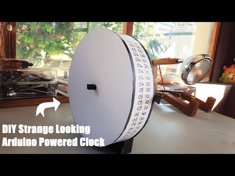)
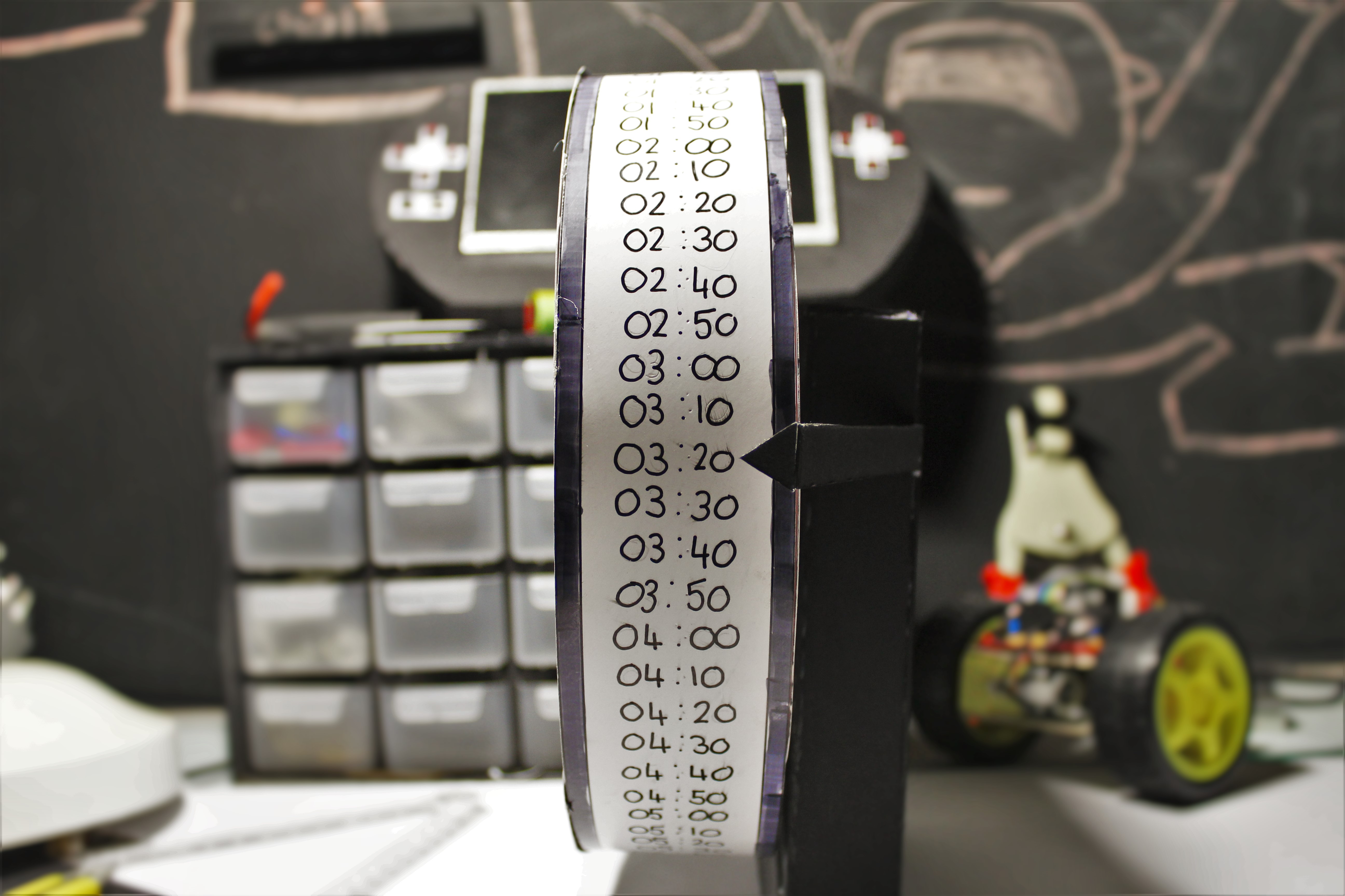
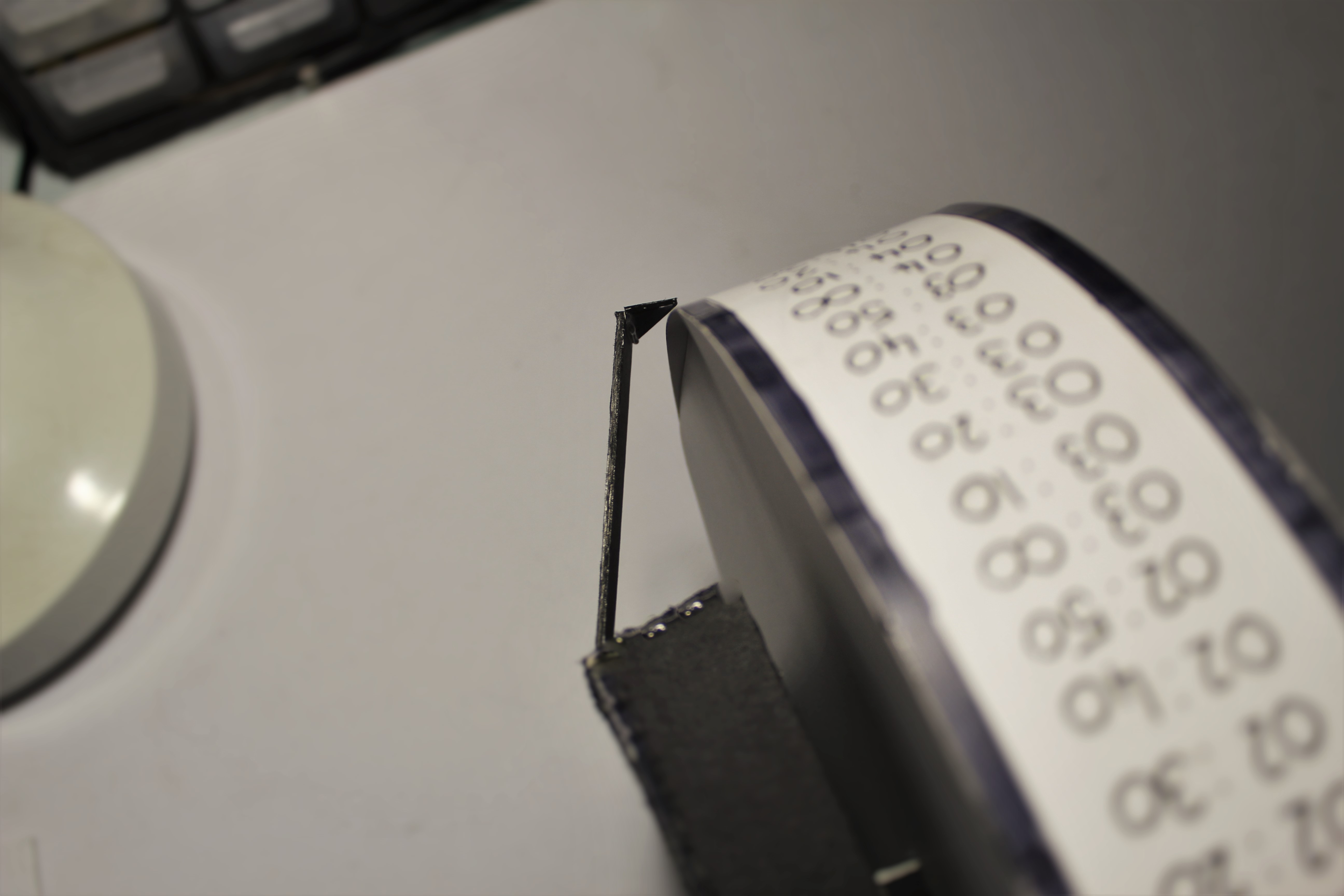
Hey everyone today im going to show you how to build a very different looking clock, powered by an Arduino. The idea behind the clock is a circle with a circumfrence of 72cm (28.3465 inch's) that ticks at 1cm every ten minutes which means every 72 ticks will equal 12 hours making it a 12 hour clock. (Its pretty complecated to expain to expain so check the pictures and video for a better understanding :D)
Parts List:
.png)
.png)
.png)
.png)
.png)
For this project you will need the following parts:
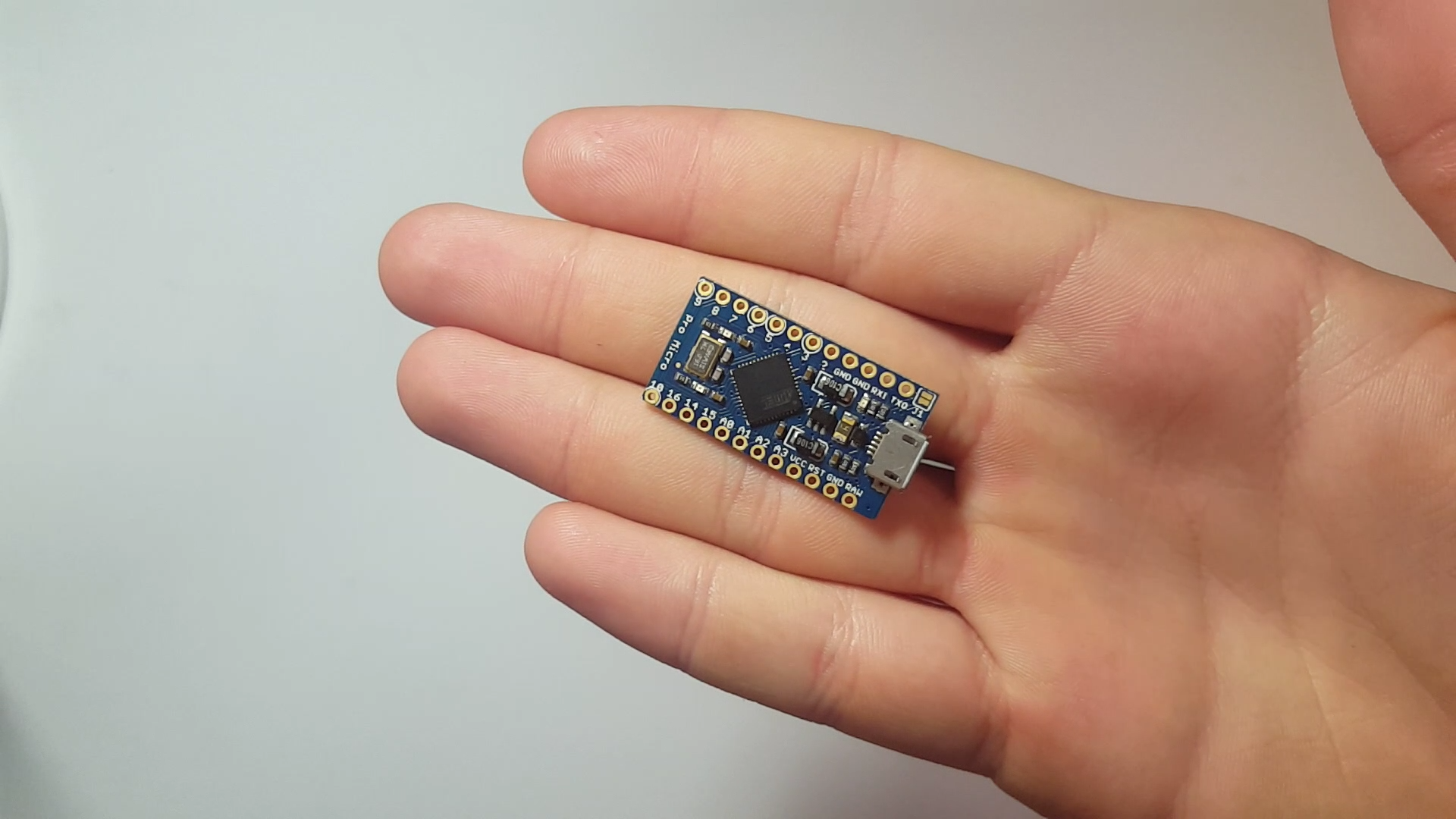
- Arduino Micro (Get it here)
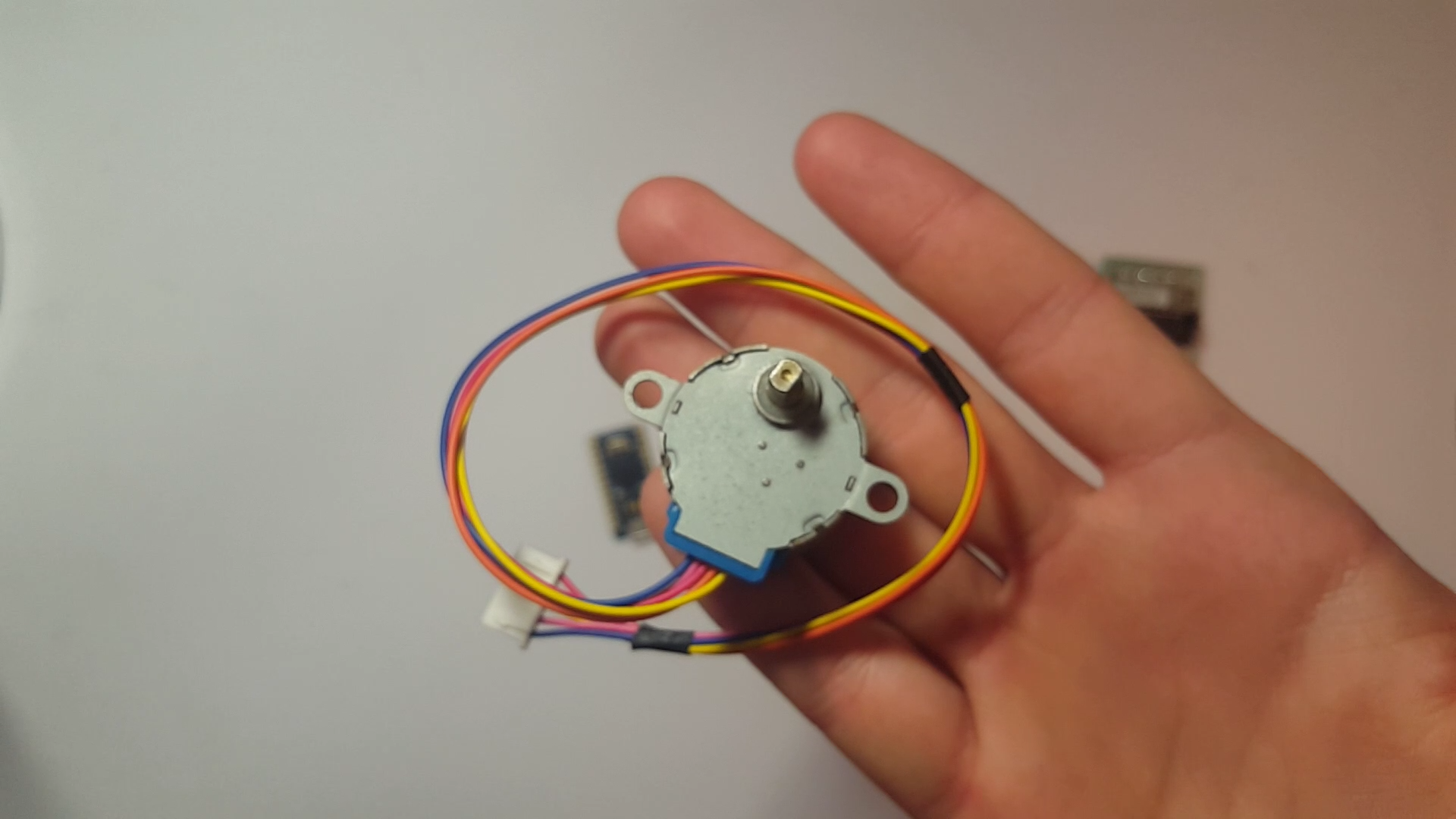
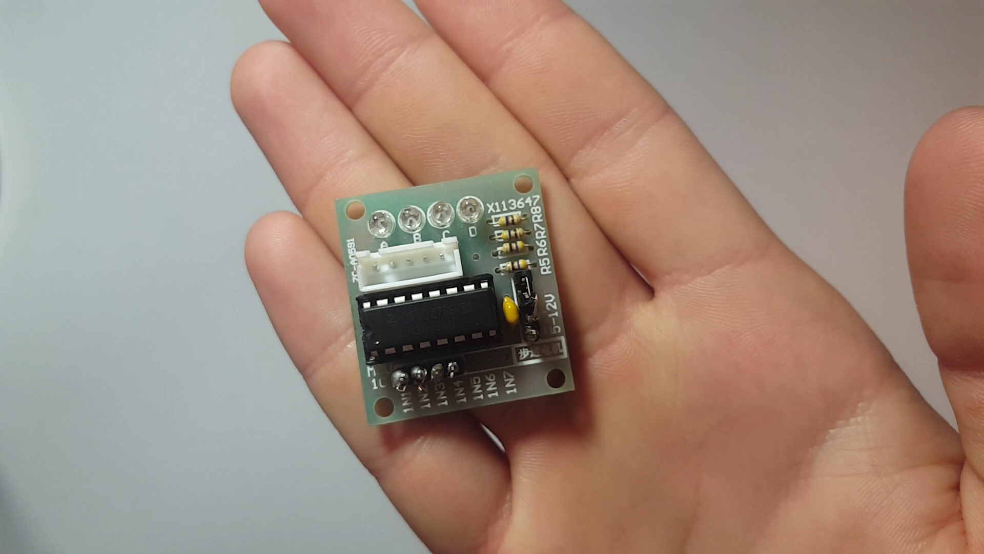
- A StepperMotor and controller (Get it here)
- Cardboard (thick and thin)
And these parts:
- A Soldering Iron
- A Glue Gun
- A Box Cutter (knife)
The Stepper Motor Libary

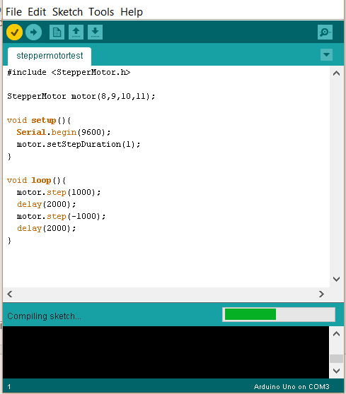

Disclaimer. You only need to install this library if you are using the less common ULN2003 MotorController, most other motor controllers will work with the pre-installed Arduino motor controller library if you are using these skip this step.
Everything I explain here can be found on this website: (http://goo.gl/Da5jEh)
- Start by downloading the .cpp and .h file I have added
- Create a new file called StepperMotor
- Drag and Drop both the .cpp and .h file into the new StepperMotor file
- Go to your Arduino libraries file and drop the StepperMotor file into it
- Open Arduino IDE and run this test code to make sure everything was installed correctly
#include
StepperMotor motor(8,9,10,11);
void setup(){
Serial.begin(9600);
motor.setStepDuration(1);
}
void loop(){
motor.step(1000);
delay(2000);
motor.step(-1000);
delay(2000);
}
6. Now verify the code in the Arduino IDE if it compiles without any issue you have installed everything correctly.
The Wiring
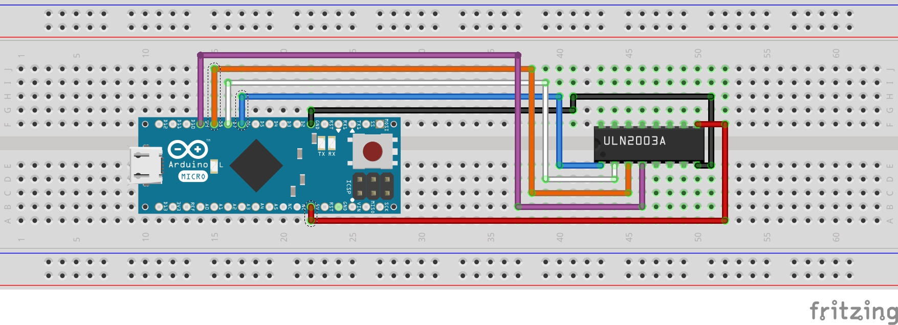
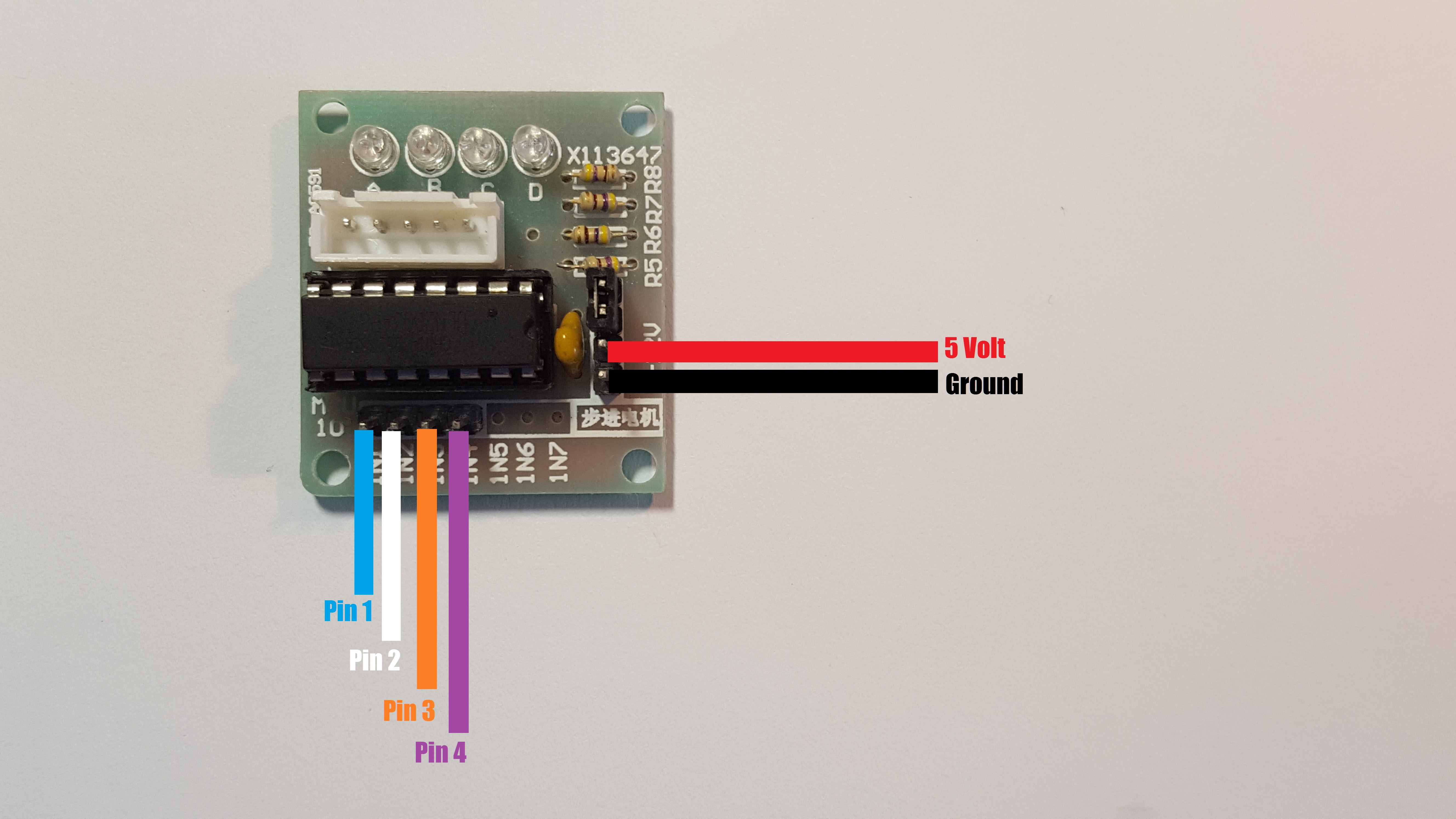
First things first plug your stepper motor into your stepper motor controller and get your soldering iron ready
Connect the Motor Controller to the Arduino in the this order
- Connect Ground on the Arduino to Ground on the motor controller
- Connect 5v on the Arduino to 5v on the motor controller
- Connect Pin 6 on the Arduino (Blue) to int 1 on the motor controller
- Connect pin 7 on the Arduino (White) to int 2 on the motor controller
- Connect pin 8 on the Arduino (Orange) to int 3 on the motor controller
- Connect pin 9 on the Arduino (Purple) to int 4 on the motor controller
Check the colour coded pictures to double check your wiring.
The Code
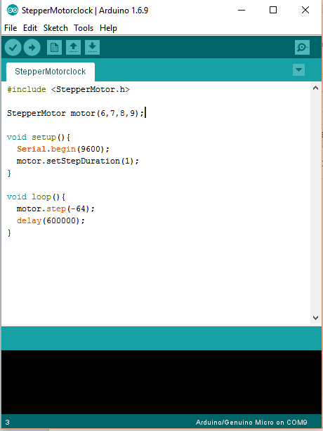
Copy the code below and paste it into your Arduino IDE and upload it to your Arduino
#include
StepperMotor motor(6,7,8,9);
void setup(){ Serial.begin(9600); motor.setStepDuration(1); }
void loop(){ motor.step(-64); delay(600000); }
The Electronics Casing
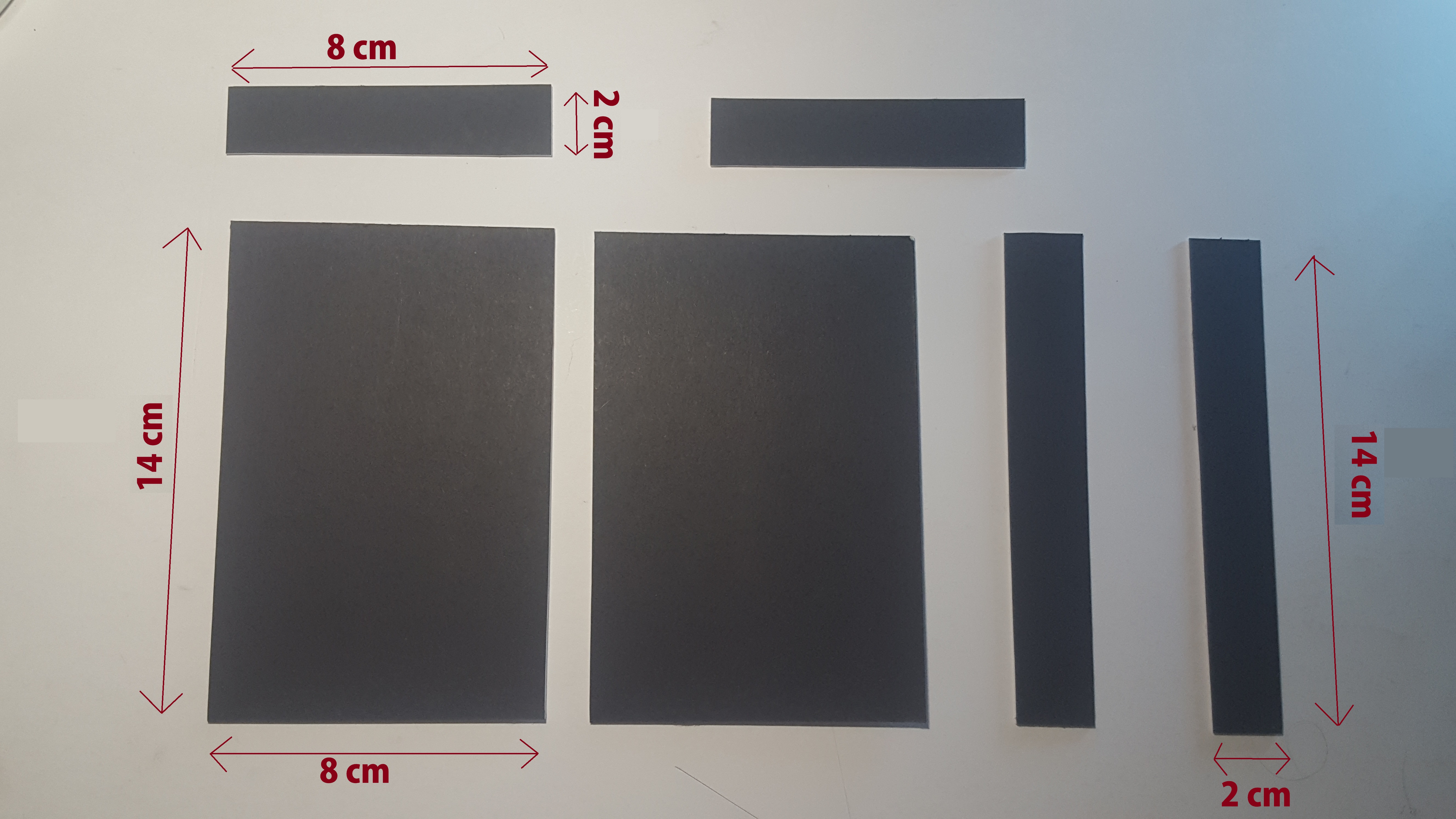
To make the casing I'm going to start by creating a box around the electronics that has a small hole allowing the motor shaft to stick out allowing it to make contact with the moving part of the clock.(To make it easier to put the clock face on we are going to make a cardboard square and glue it onto the motor shaft, see photos)
Creating the Clock Face
.png)
.png)
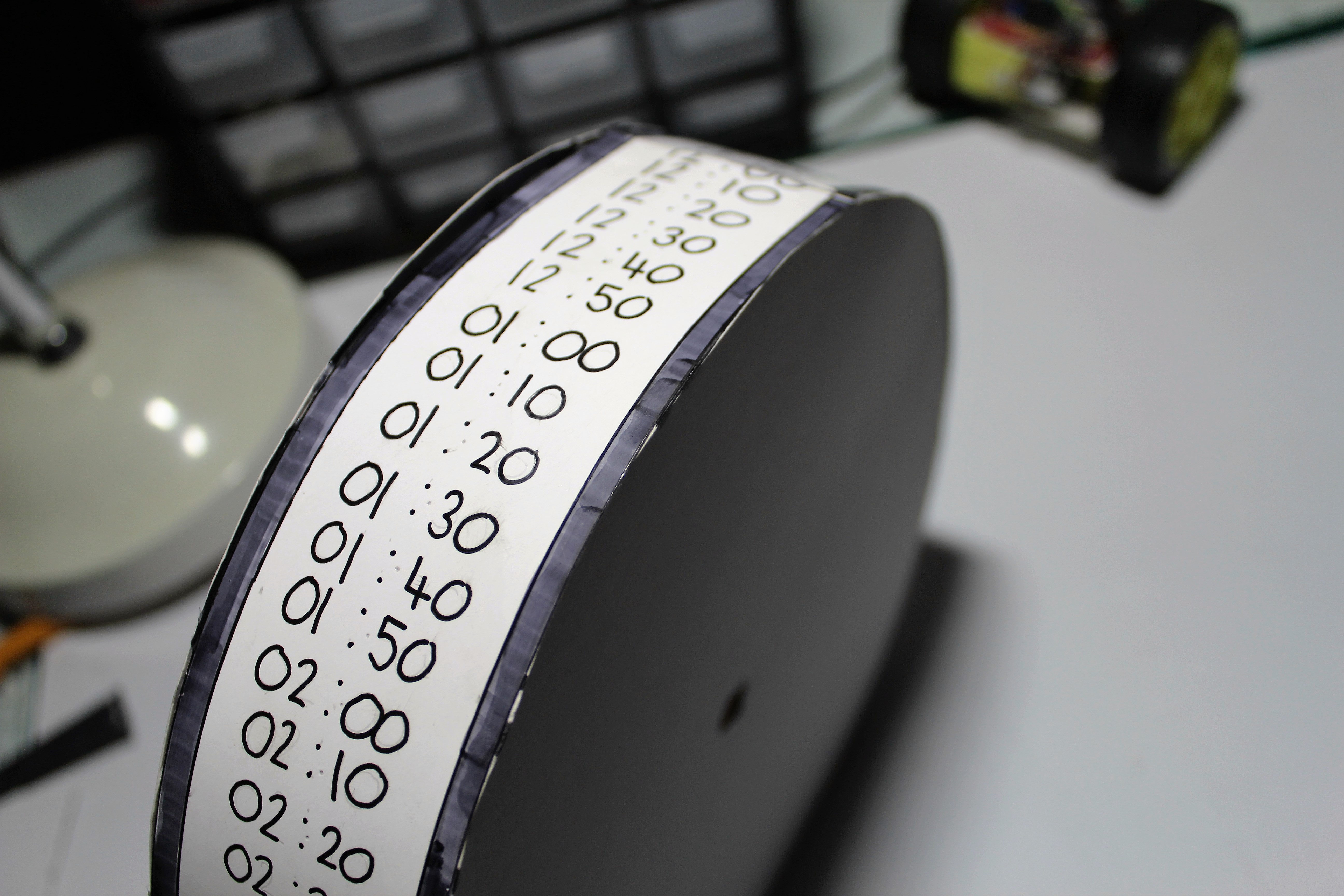
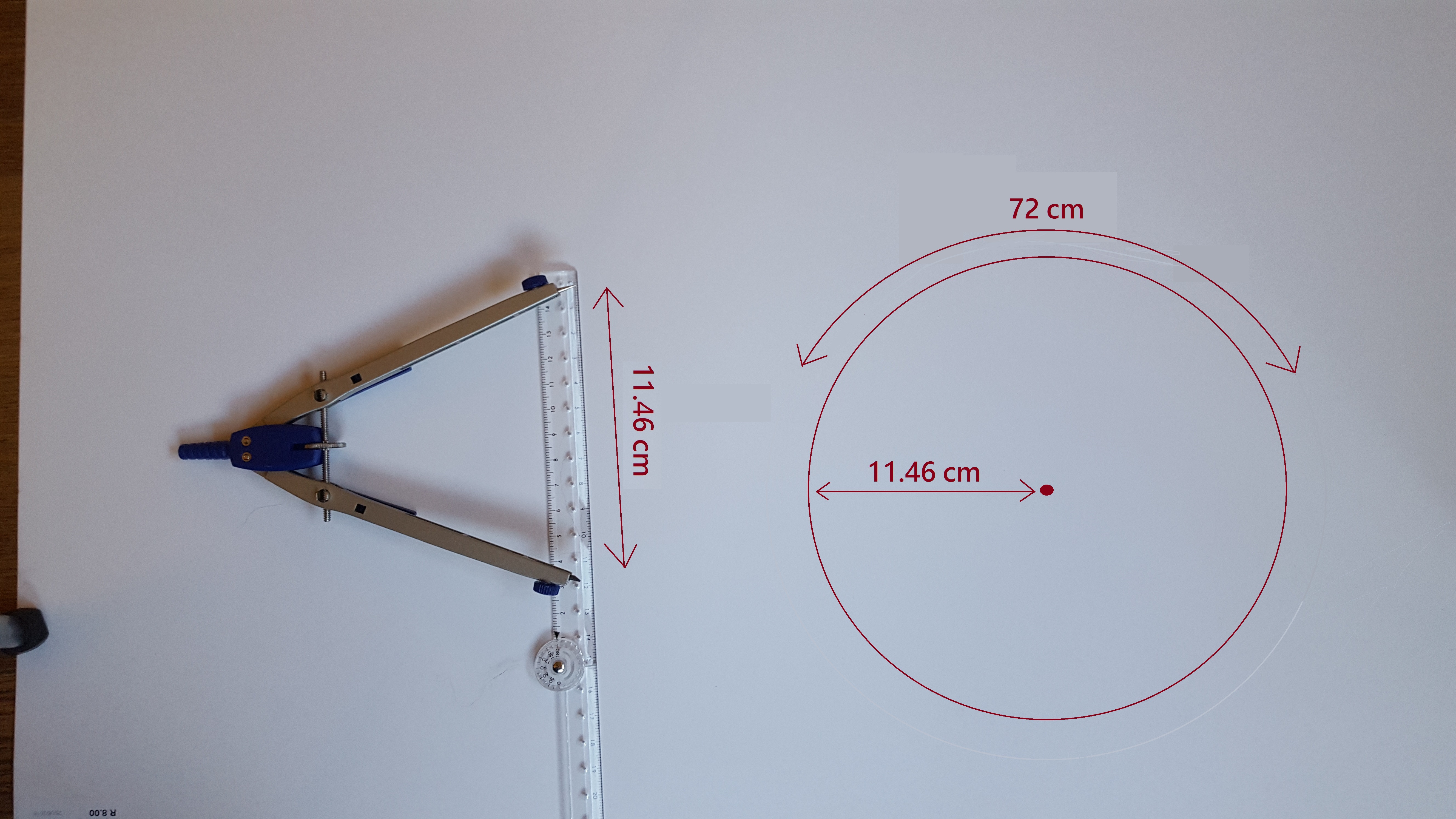
To start off we need to figure out the basics of the clock face, now normal clocks have 3 hands around a 12-hour face allowing the user to see seconds, minutes and hours now with our clock we only have 1 "hand" which means we have to maximize our space. My final idea was to create the circle with a circumference of 72 cm (not too big and not too small) which means each "tick" will move the circle by 1 cm therefore meaning that 1 cm equals 10 minutes (720 minutes in 12 hours). All of this is a little confusing but the pictures do help with the understanding.
- Start by getting a compass(drawing tool) and opening it to 11.46cm which is the radius of the circle.
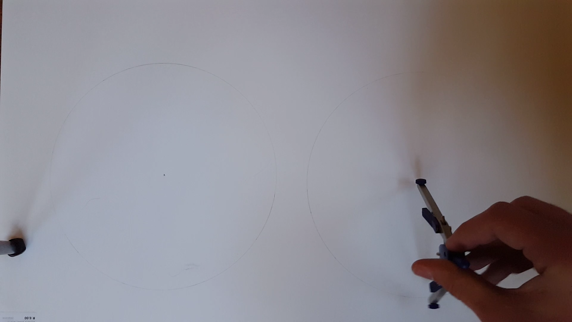
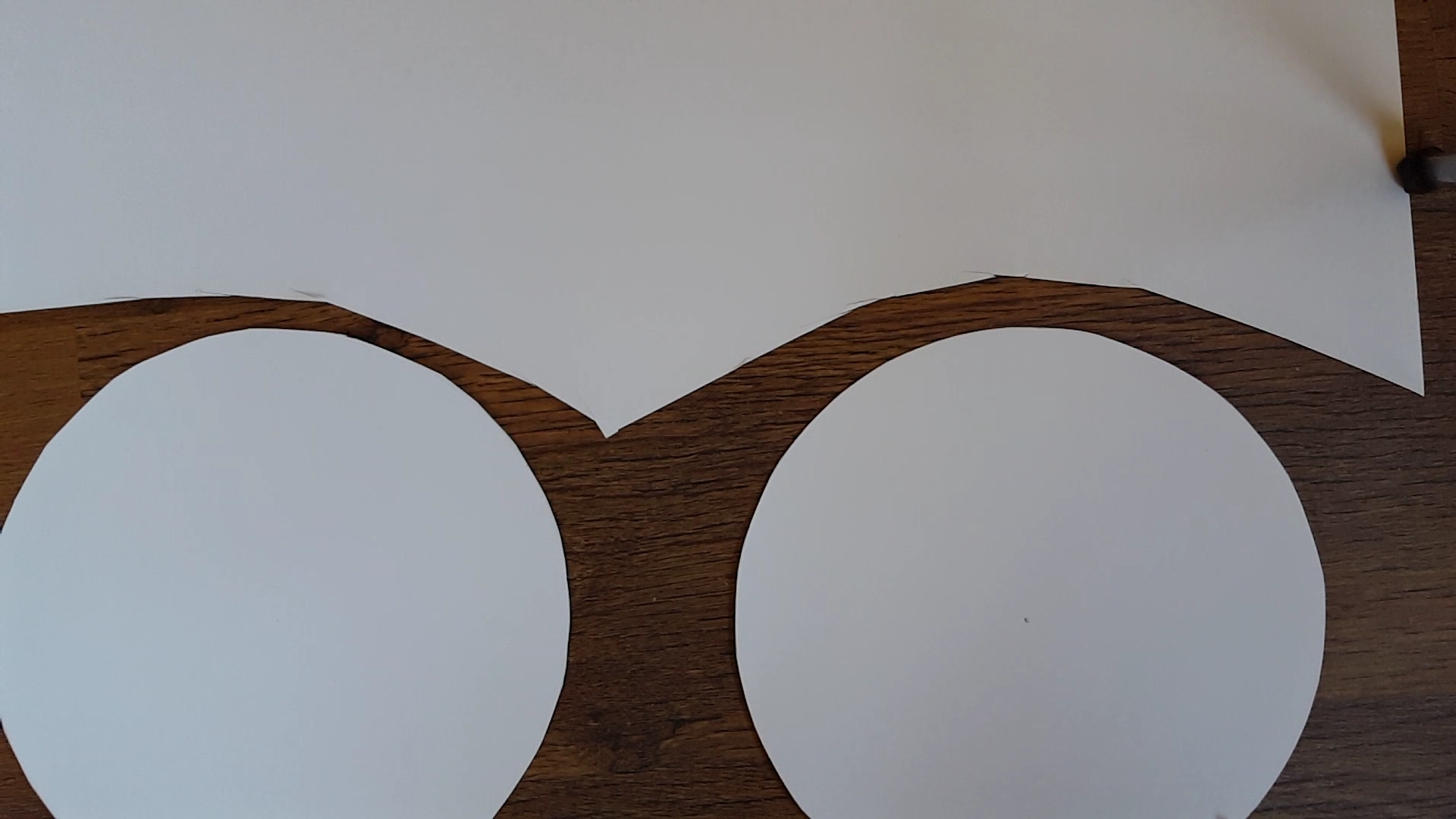
- Draw two circles and cut them out.
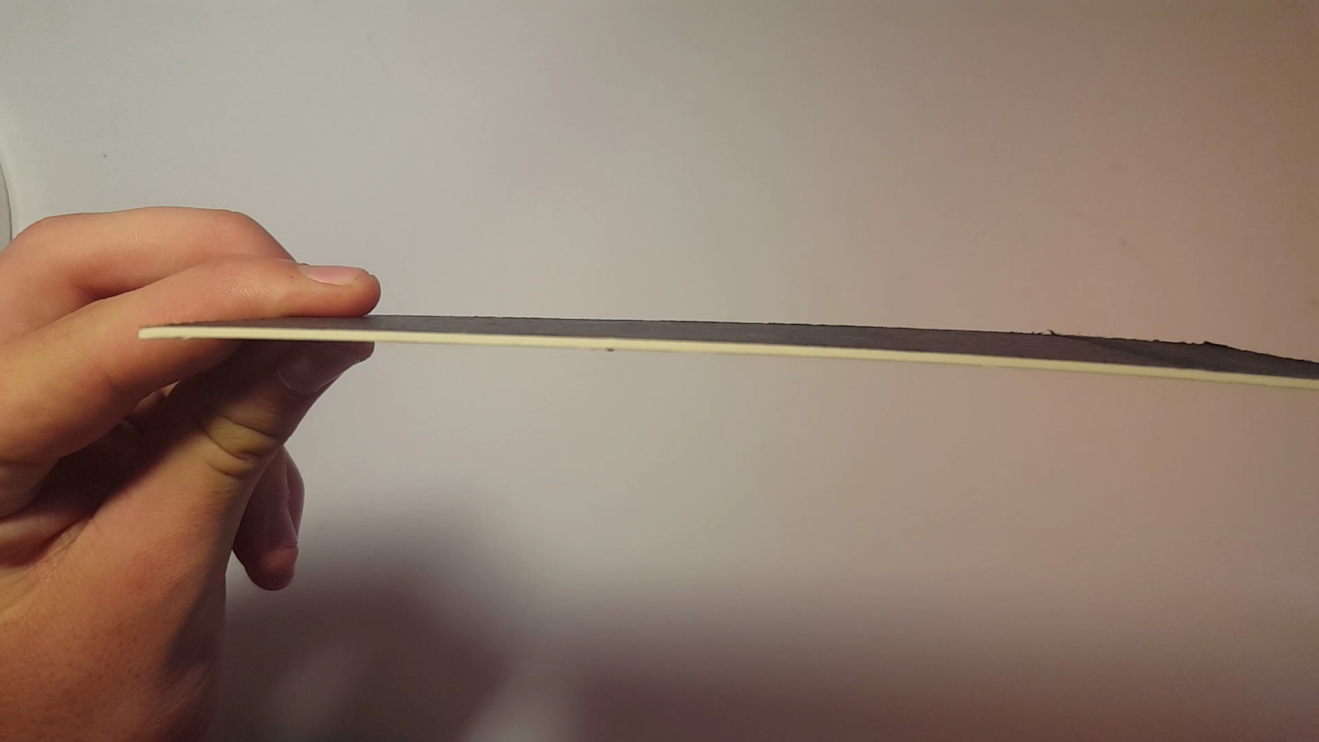
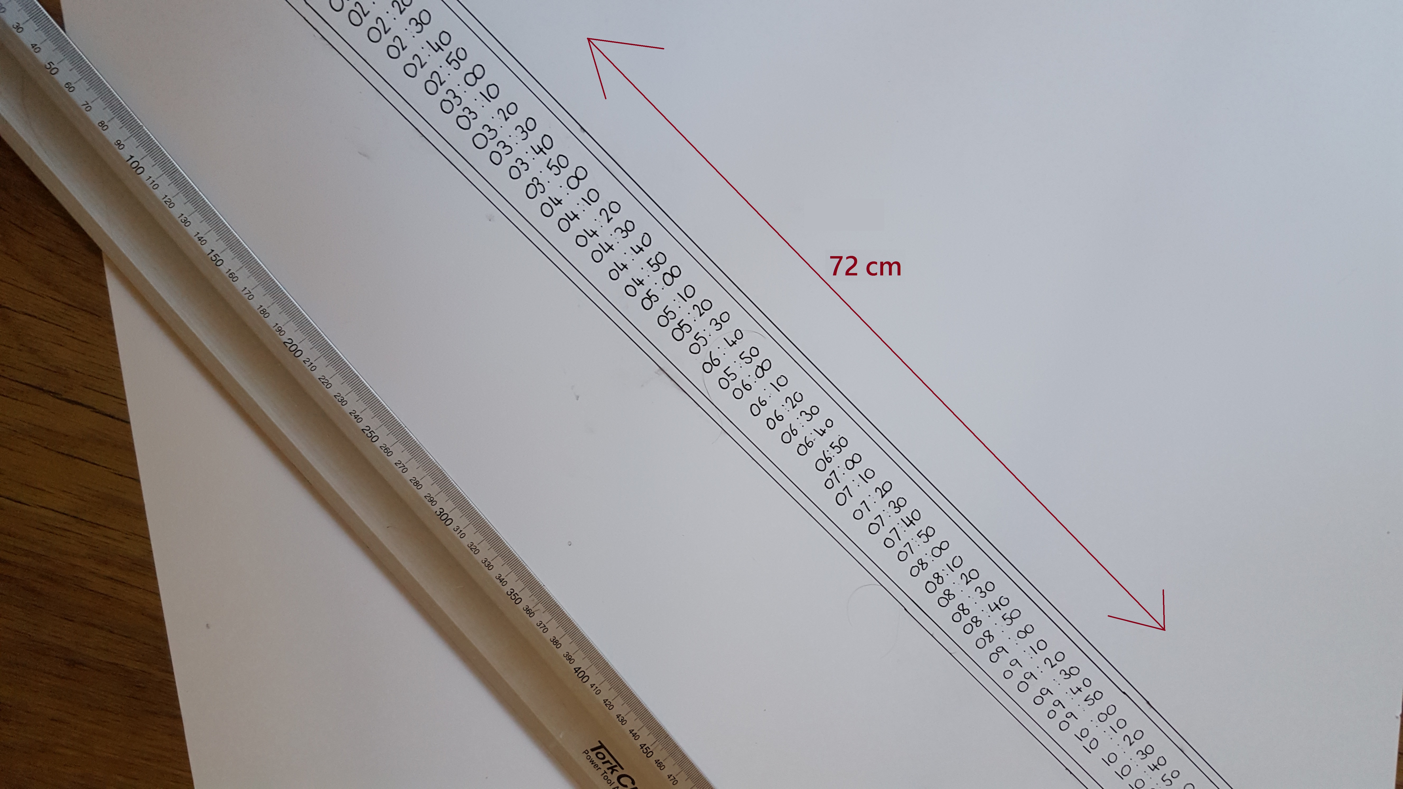
- now grab a thin piece of cardboard and cut a strip measuring 72cm in length (The strip should be 5cm wide but its not very important how wide it is.)
- Now on the strip measure and mark every cm.
- Now draw time intervals on each mark (like this 12:00, 12.10, 12:20, 12:30, 12:40, 12:50, 01:00, 01:10.... until you get to 11:50 which would be at the end of the sheet)
- Cut square holes in the middle of both circles
- Glue the strip we cut out in between the two circles to make a mini cylinder
Putting It All Together
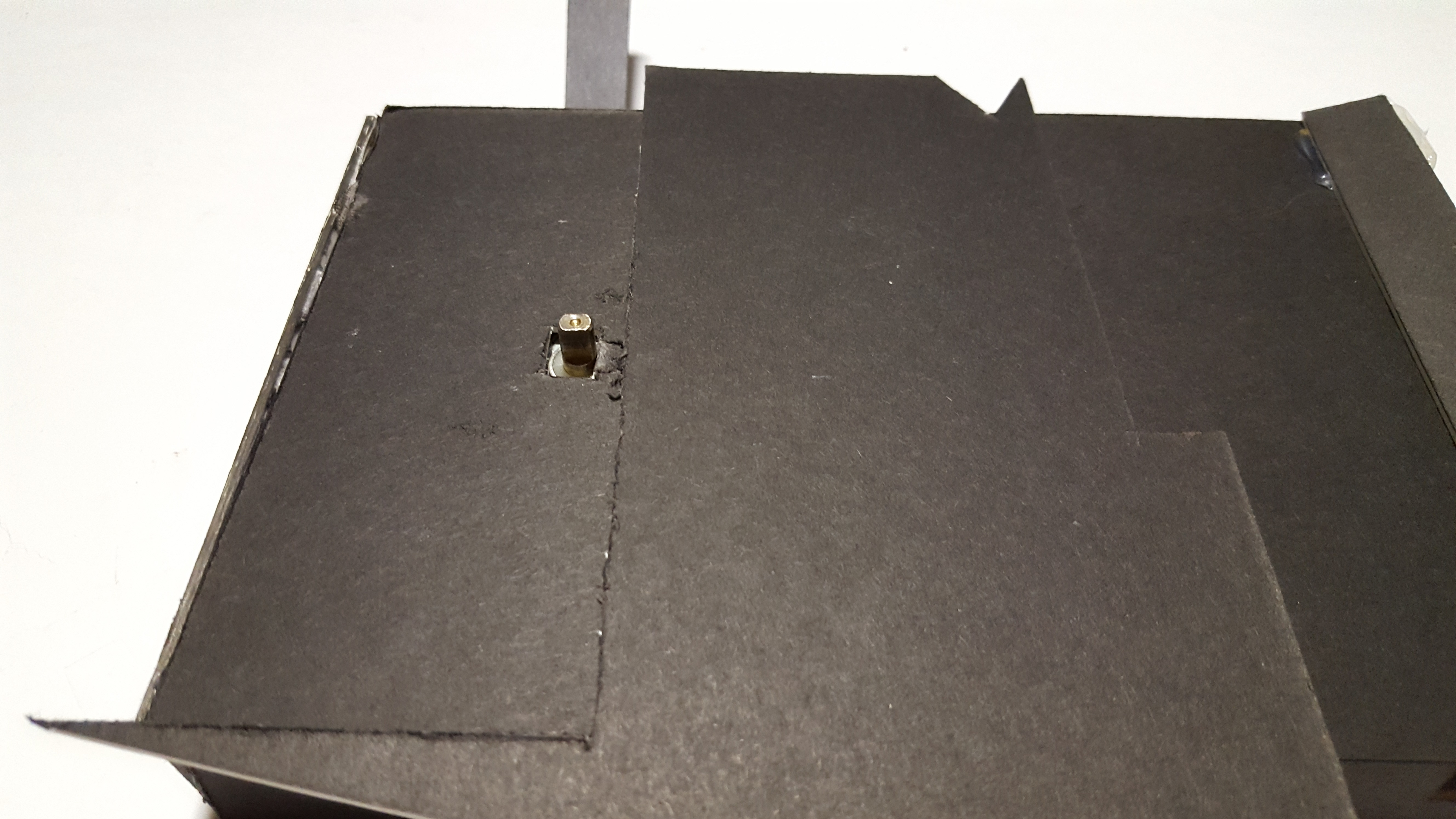
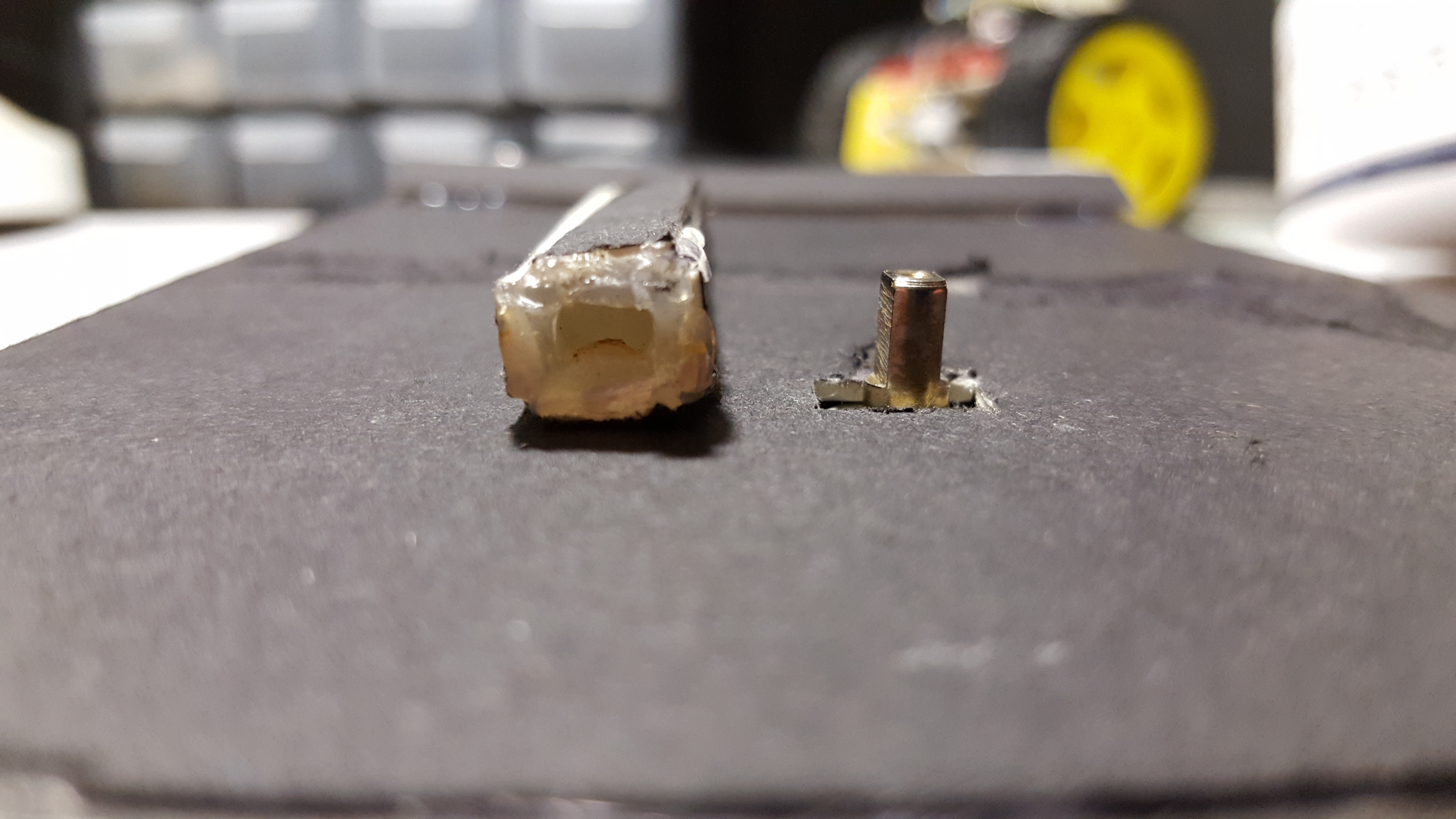
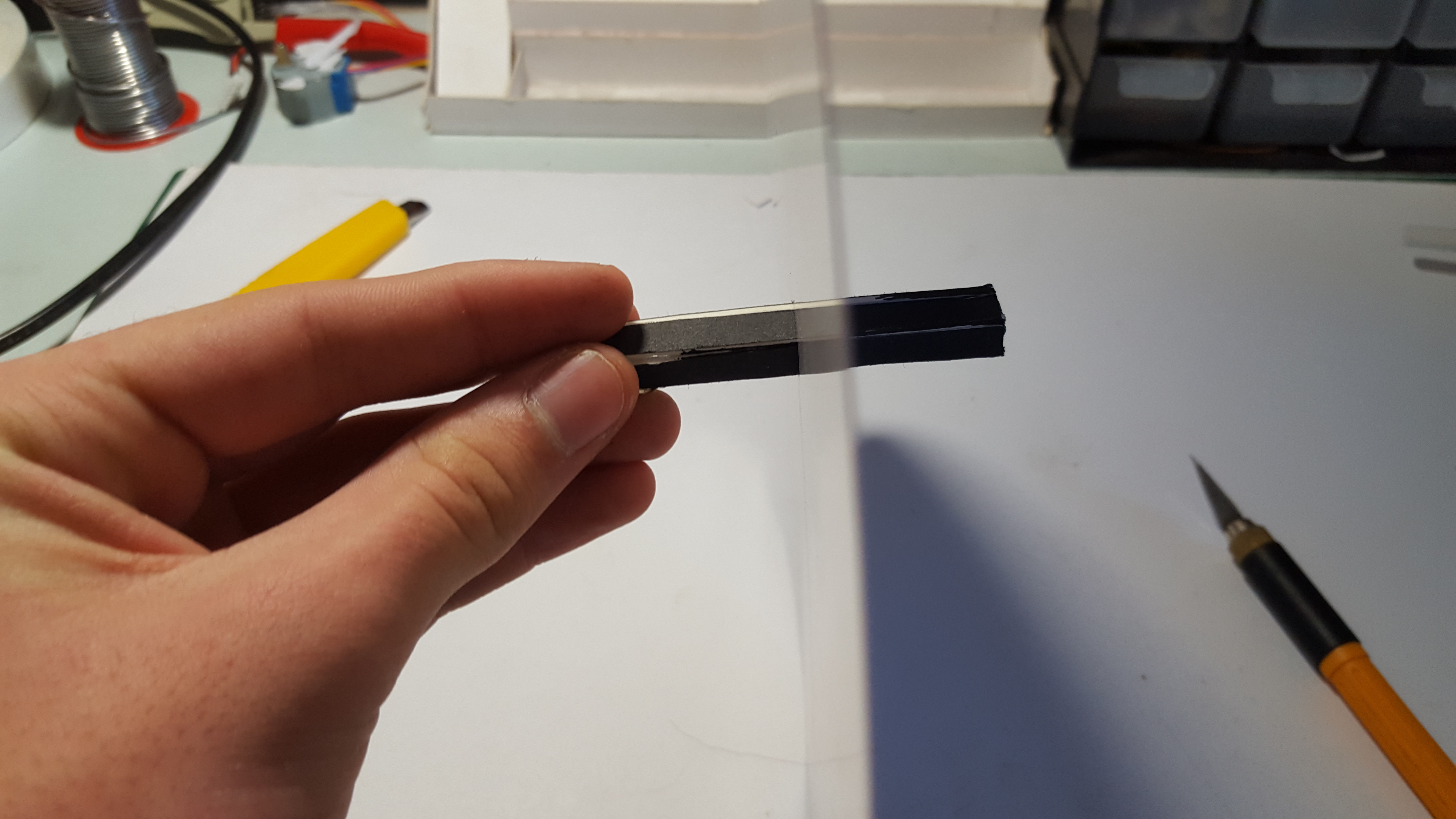
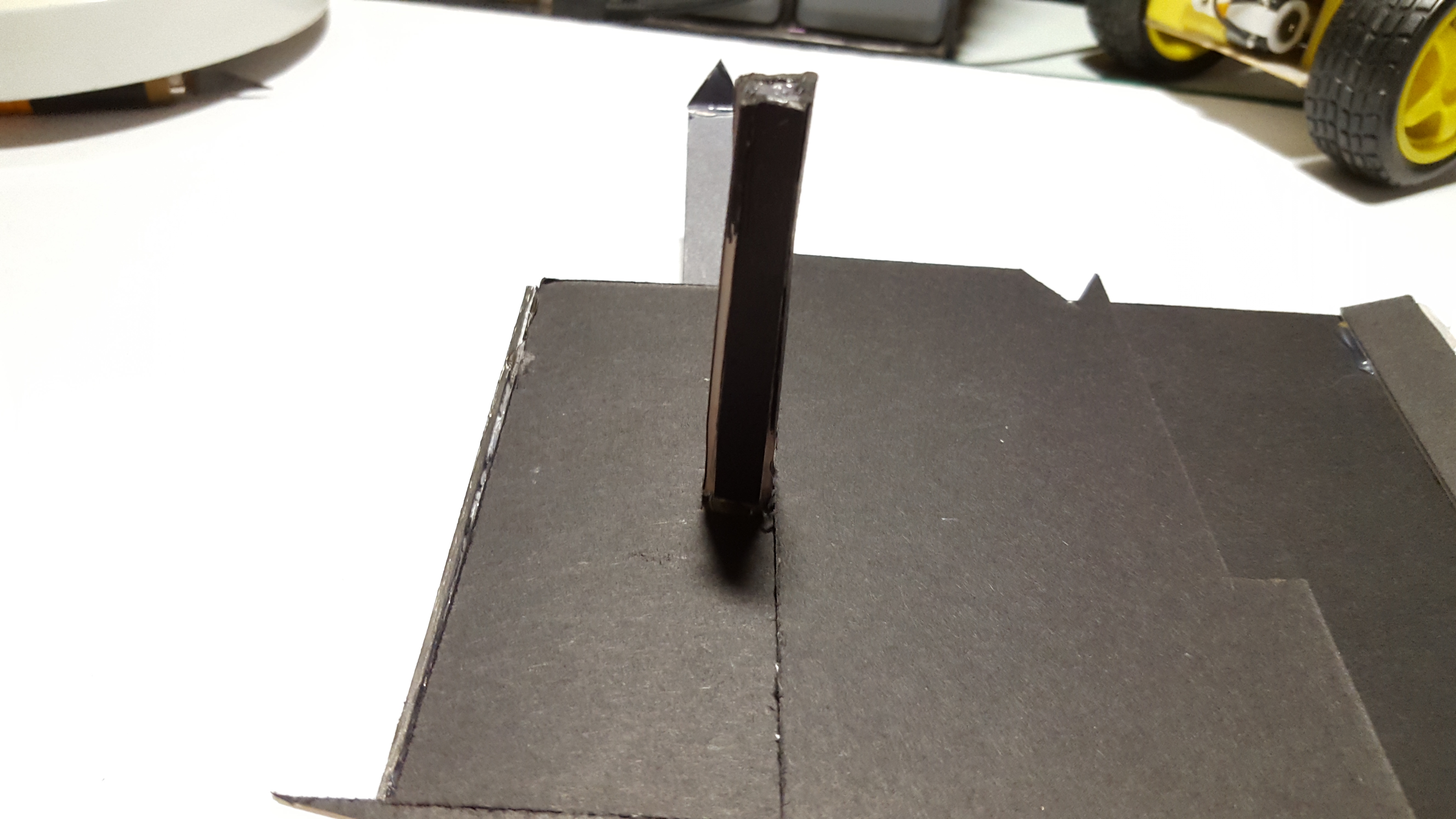
Put the peaking out part of the motor (that turns) into the square we made in the circles and glue it together (see pictures). Once its all together we can test it out and make sure it works and ticks in time.
If you have any questions please message me or leave a comment and ill try my best to get back to you. Thank you so much for reading