A Tiara for Your Princess
by CmdrZin in Craft > Costumes & Cosplay
841 Views, 0 Favorites, 0 Comments
A Tiara for Your Princess
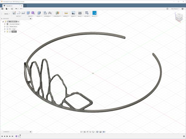
Assumes basic knowledge about creating and modifying objects in Fusion 360.
These steps will show you how to create a Tiara for your princess that can be scaled up or down. The process is to make a cylinder, like a soda can, then punch holes in it, shape the holes to smooth out the edges, and finally thicken the walls to make a 3D printable object.
Create a MESH Mode Cylinder
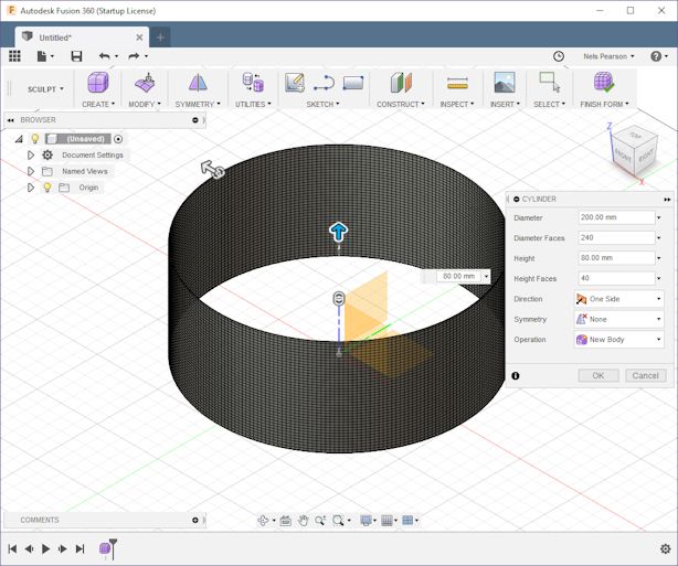
MESH mode will be used to create a pattern on a cylinder surface since Fusion 360 does not have a 'wrap' operation.
Go to MESH mode. CREATE > Create Form (icon) > OK.
CREATE > Cylinder. Use the XY plane. Put the Center at the Origin. Make the diameter 200 mm and height 80 mm. Increase Diameter Faces to 240 and Height Faces to 40. This makes the squares about 2 mm/sq.
Trim Away Back Half to Improve Redraw Rate
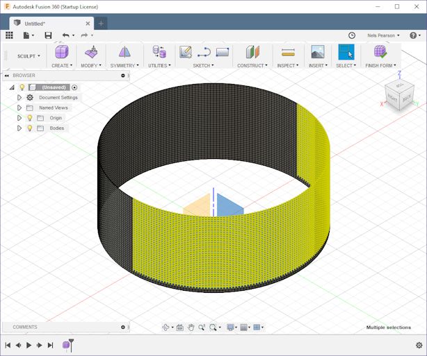
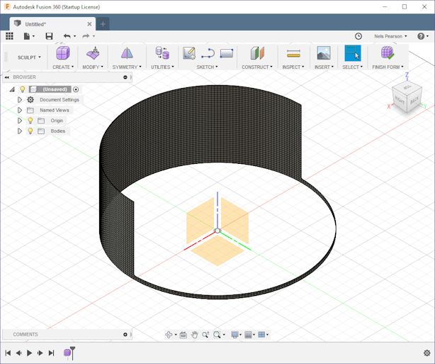
Using the Right-Top view, drag a mouse select window over the back half of the cylinder to select all of those squares. Then with the back view. Then press the CTRL key and select the bottom two rows to deselect them. Press the DELETE key to remove all the selected squares. This will help improve the redraw rate.
NOTE: This process may take a minute or two. Lots of calculation to be made.
Define the Basic Pattern by Punching Holes in the Cylinder
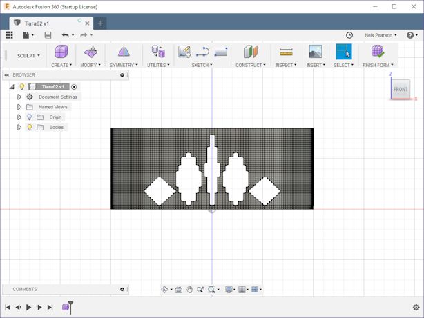
Using the Front view, select faces (squares) and delete them holes. These are just rough cut outs for now. Leave the bottom two rows solid to give this a 4 mm base. Also leave at lease one square between any holes and two along any outside edge.
Select squares (faces) to remove, then deselect the outer edges and press DELETE to remove them. If you don't deselect the outer edges, the delete operation would also remove the adjacent squares. To keep things symmetrical, duplicate a hole on both sides of the center line before moving on to a new hole.
NOTE: A quirk of Fusion 360 deselection is that if you overlap a face when the selection window moves right to left, it deselects the overlapped faces and edges. If you move it from left to right, it only deselects the edges.
For this example, I will only make a few cutouts.
Initial Smoothing by Removing Vertices at Sharp Corners
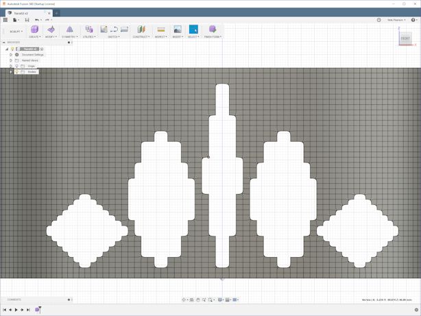
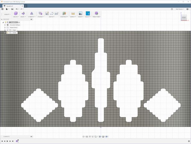
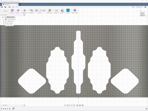
Delete sharp corner vertexes to smooth an opening.
Remove Excess
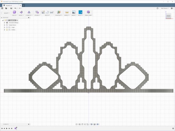
Delete faces around the holes to define a lattice structure.
Smooth Edges by Removing Verticies at Sharp Corners
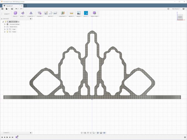
Delete sharp corner vertexes to smooth edges. Holding down the SHIFT key lets you select succesive verticies so you can delete all of them together.
The Hard Part: Edit the MESH for the Final Design
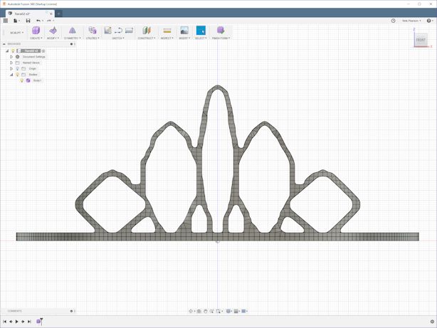
Select MODIFY > Edit Form. Use Transform Mode: Translation and Selection Filter Vertex or Edge base on which type you are adjusting.
To maintain symmetry, work with pairs of points, one on each side of the center of the hole. It's also easier to flatten a concave edge first and then push a convex edge to get the right thickness.
Optional: Break the Ring to Allow It to Flex
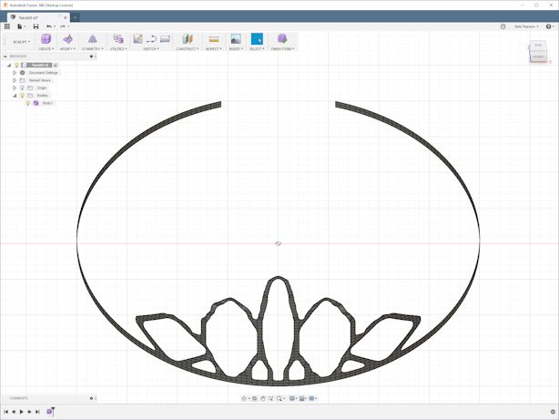
If you want the fit to be adjustable, remove about 20 squares from the back part of the cylinder. This will allow it to flex a bit.
Thicken the Mesh
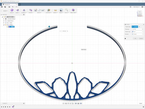
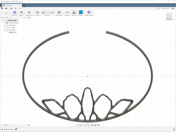
Select MODIFY > Thicken and use either Thicken Type Sharp or Soft. Use Thickness: 3 mm. > OK
Completion
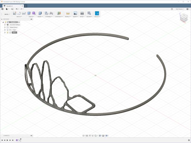
Select FINISH FORM. Select Body > Create Component from Bodies. Rename Component1:1 to Tiara. Save as STL and send to your favorite slicer app and then print.
NOTE: I had to scale it by 90% to get it to fit on my printer bed.