A Raspberry Pi Powered Junk Drum Machine
by banjowise in Circuits > Raspberry Pi
15558 Views, 55 Favorites, 0 Comments
A Raspberry Pi Powered Junk Drum Machine
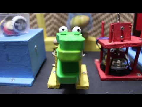
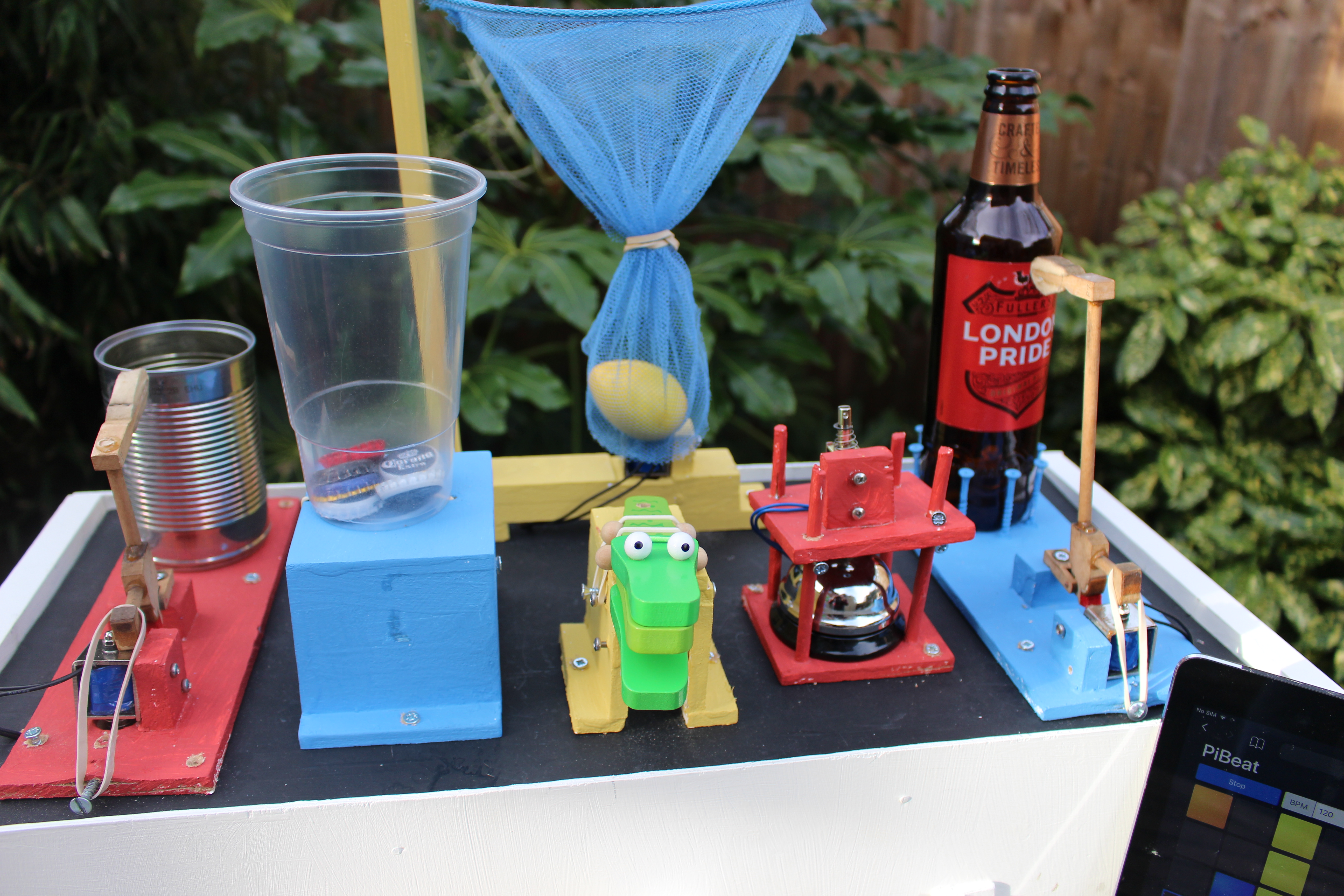
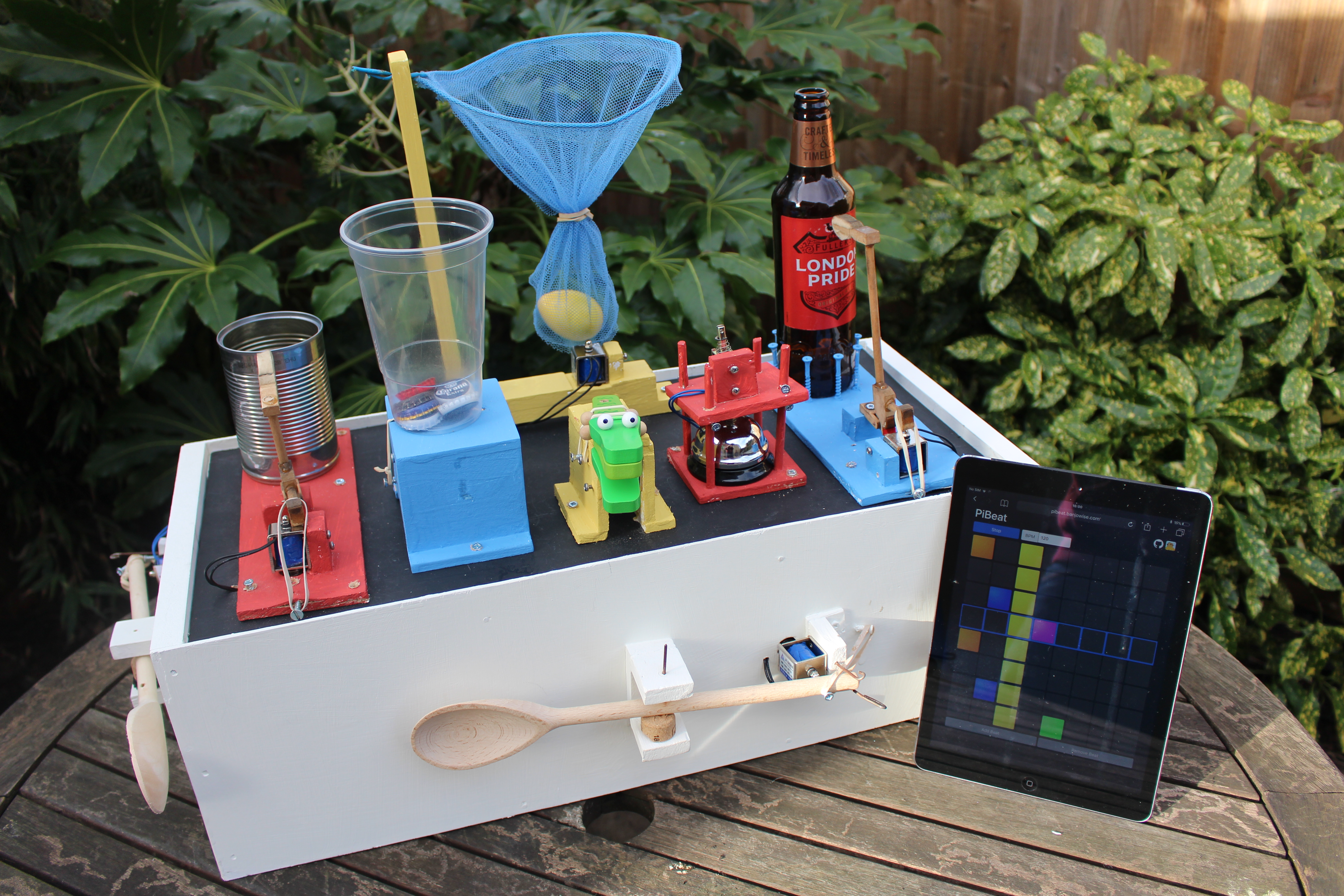
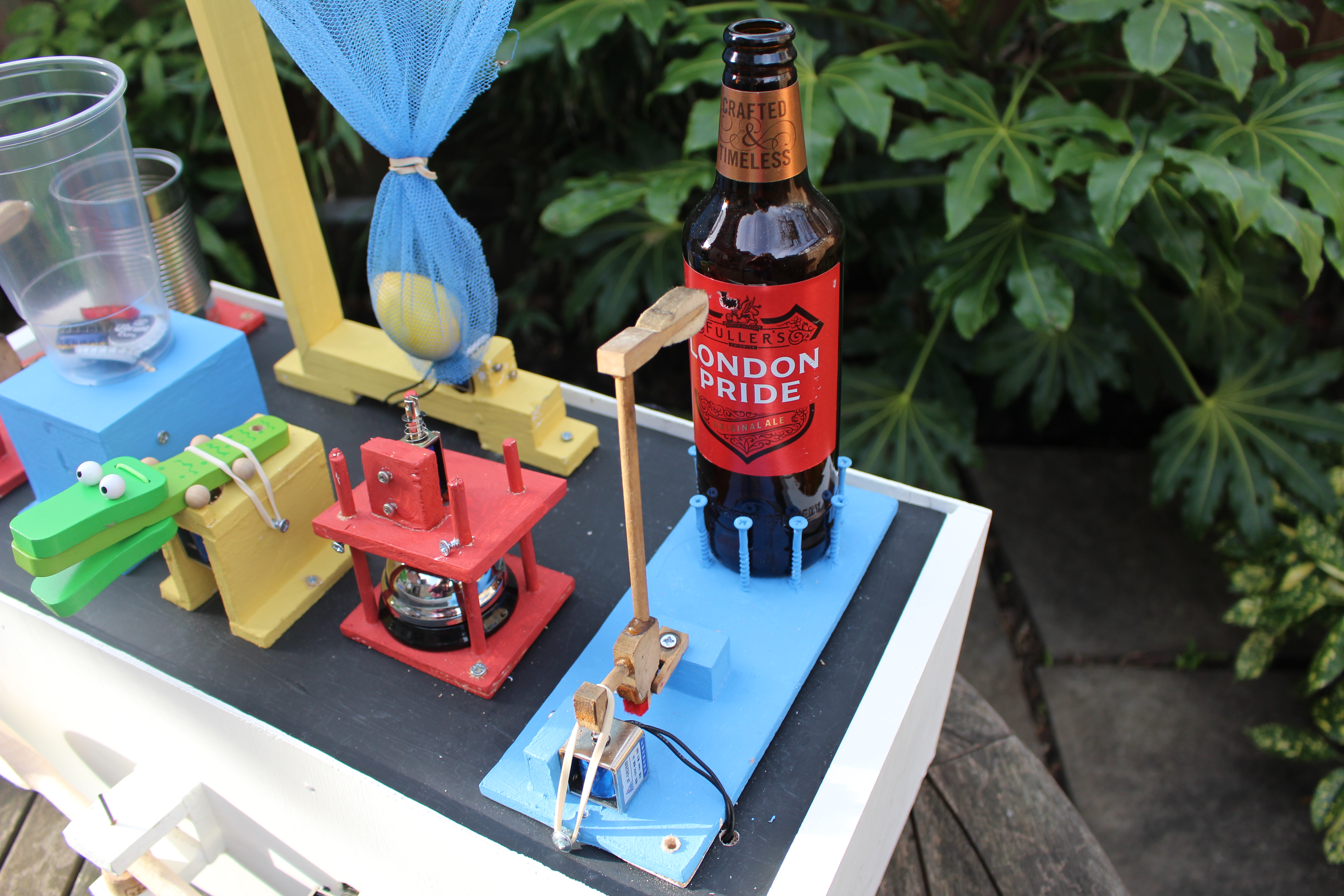

This Instructable will show you how to make a Raspberry Pi powered robotic drum machine. It really is a fun, creative, interactive project. I’ll show you how to make the internal workings, but the actual drums is going to be up to you, giving you the opportunity to make something completely unique to you. For my machine I have used as many found items as I can... hammers from a piano rescued from my neighbours skip, a fishing net I found on the beach, an empty bake bean can, wooden spoons, an empty beer bottle, beer bottle tops and a desk bell among other things, but let your imagination go crazy - see what you have around the house, just about anything that makes a noise when hit can be used, and it will really make your project your own.
To control it, you have 2 options:
- A browser based step sequence which I have called PiBeat - This is great fun and lets you control your drum machine interactively from your Pi, or any device on the same network (such as your phone, tablet or computer). We will install it on your Pi later, but a preview can be seen here, and the code is in GitHub here.
- A python script to program a drum pattern. This is a great way to create a rhythm for you to jam along with on your guitar etc.
I try to keep costs down and as you will see in the next step, no expensive specialist tools are required. I have also tried to explain how things work in every step, making it a great project even if you are a relative newcomer to the world of Pi's, coding and electronics and on a limited budget.
OK, let’s get to work!
Go Shopping
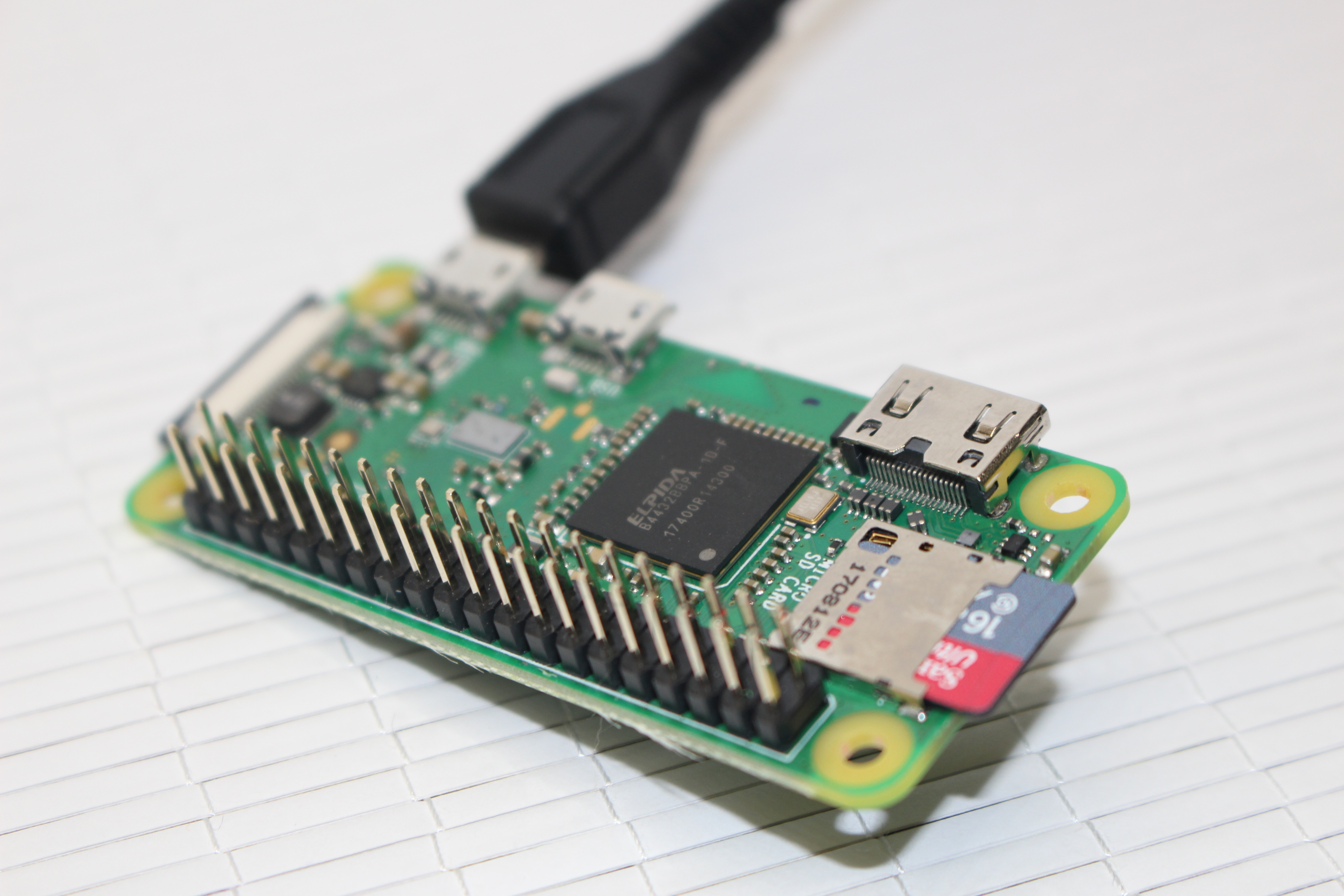
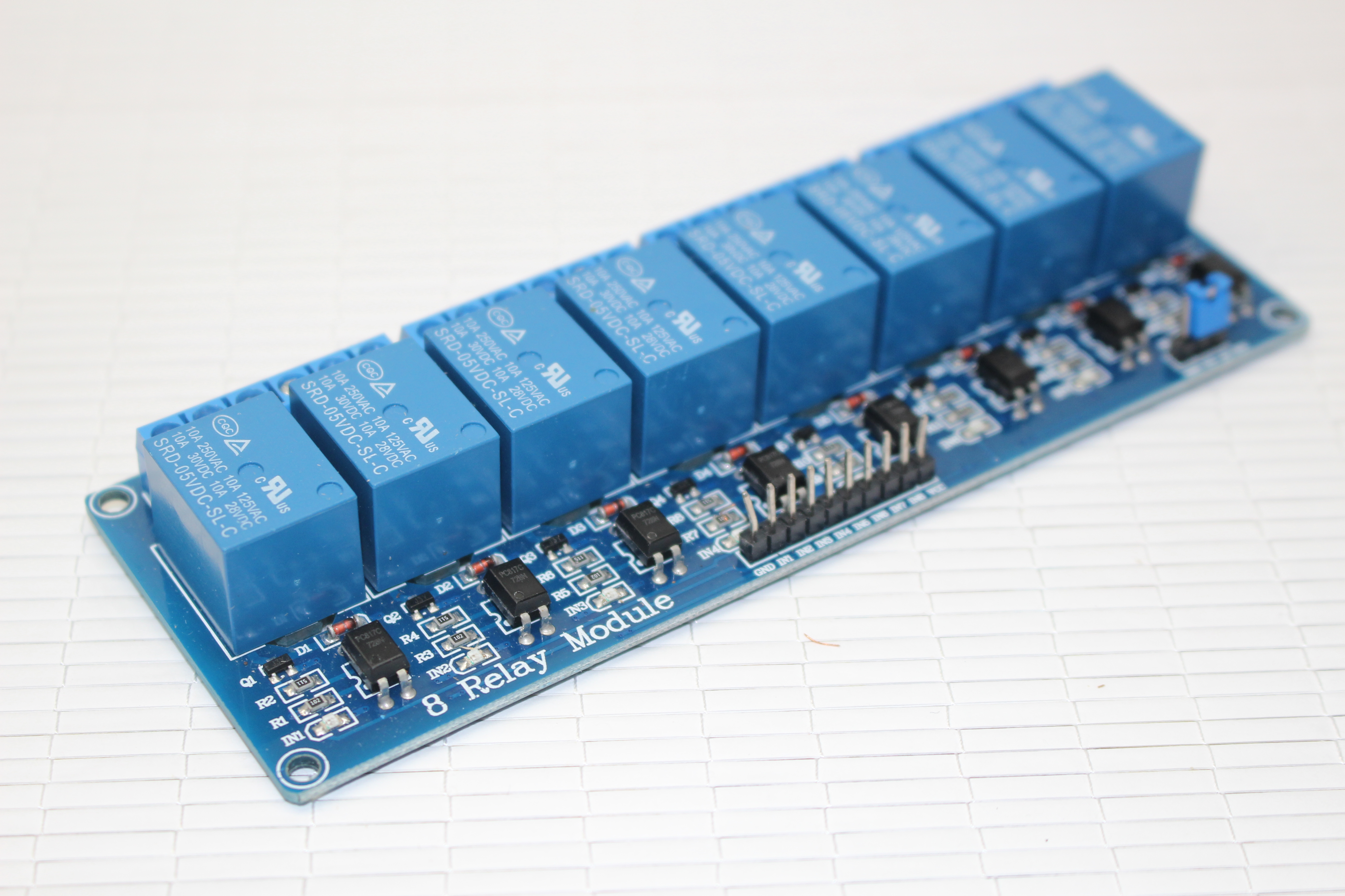
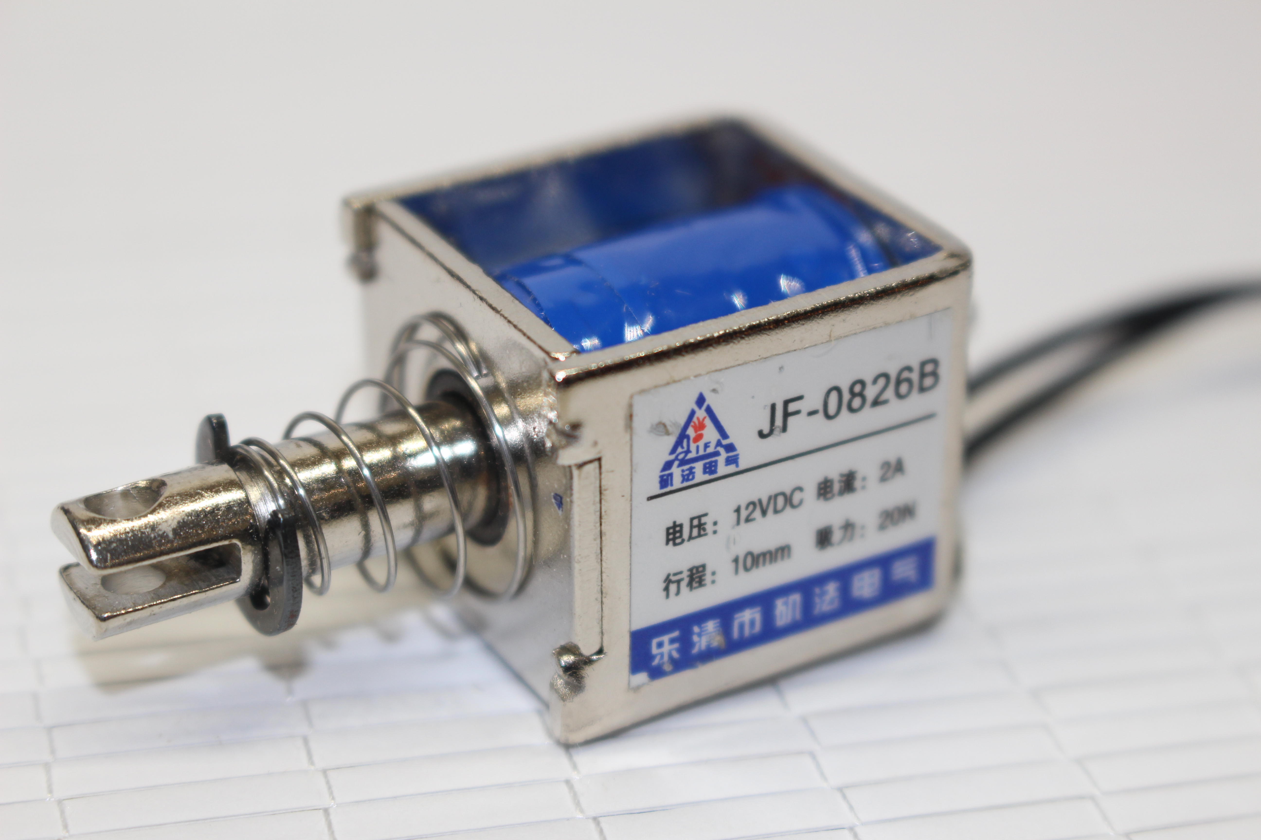
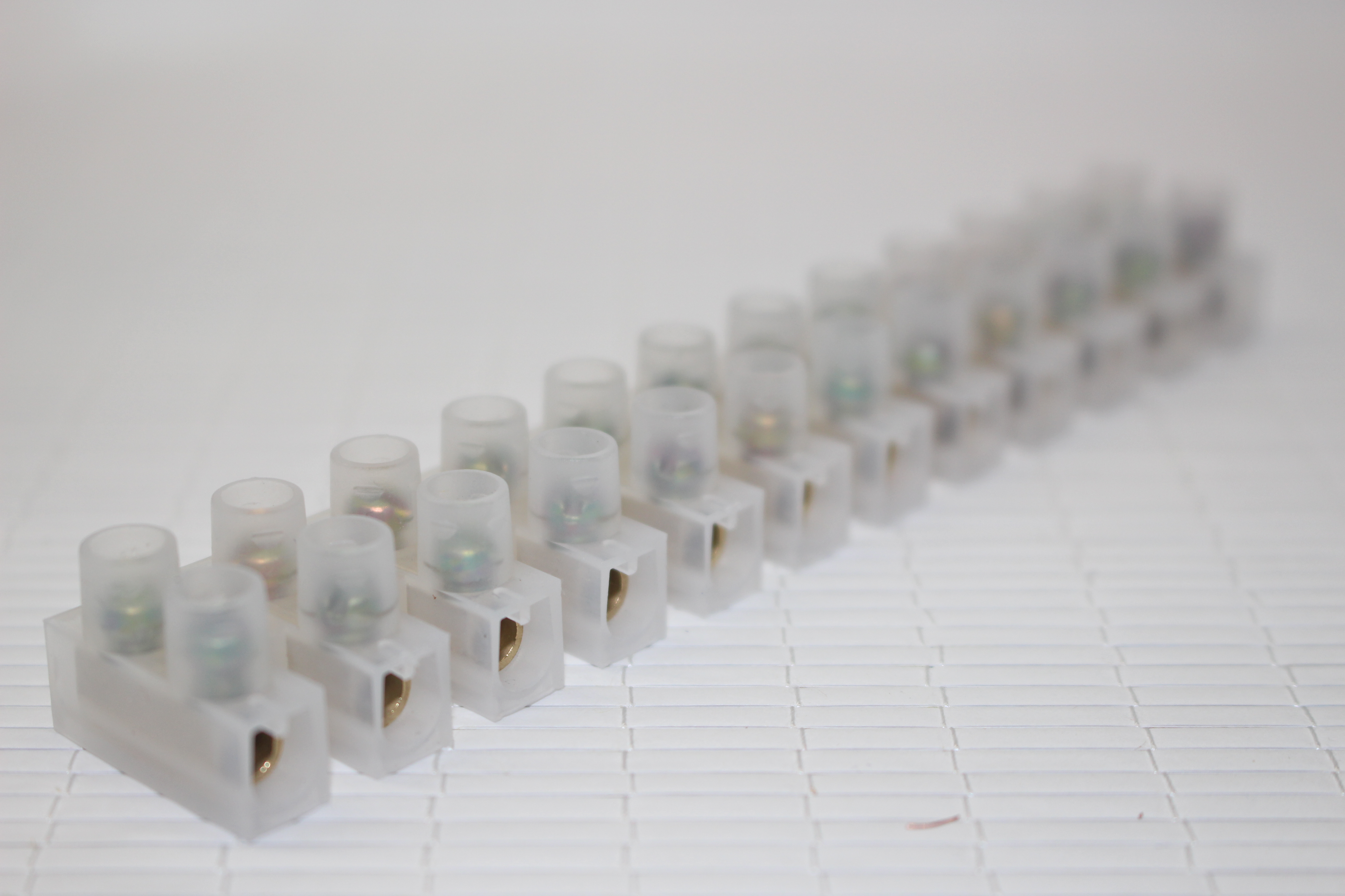
To build the internal mechanism, you will need:
- 1x 40 Pin Raspberry Pi with Raspbian installed on a SD, with power cable and ability to connect into it (I've used a Raspberry Pi Zero Wireless with pre-soldered header from ModMyPi)
- 1x 5v 8 channel relay
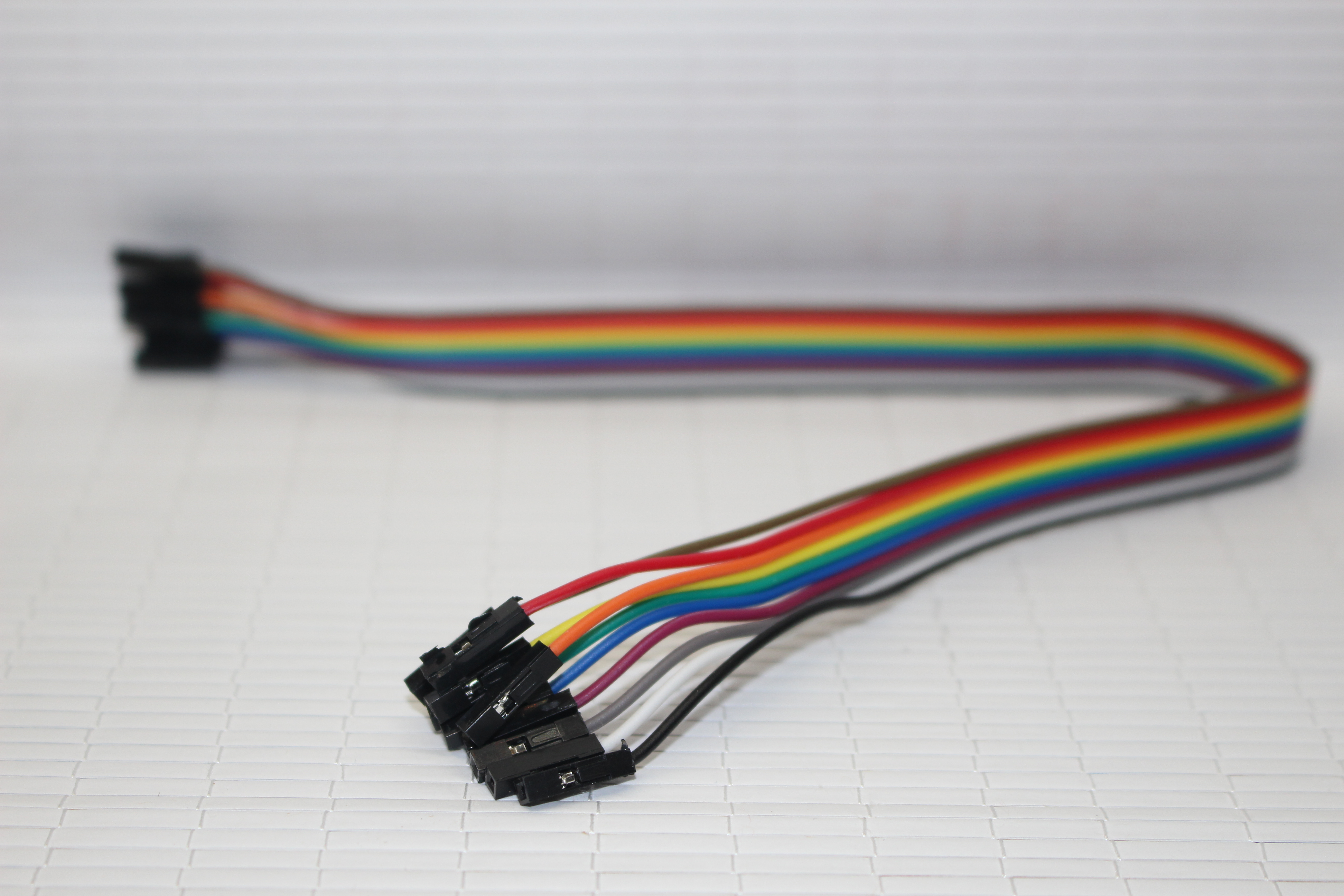
- 1x Pack of female to female jumper wires (10 wires needed)
- 2x 3 Amp Terminal strips (You could use a breadboard or perfboard, but terminal strips are cheap and prevent cables coming loose, and when making this I didn't own a soldering iron)
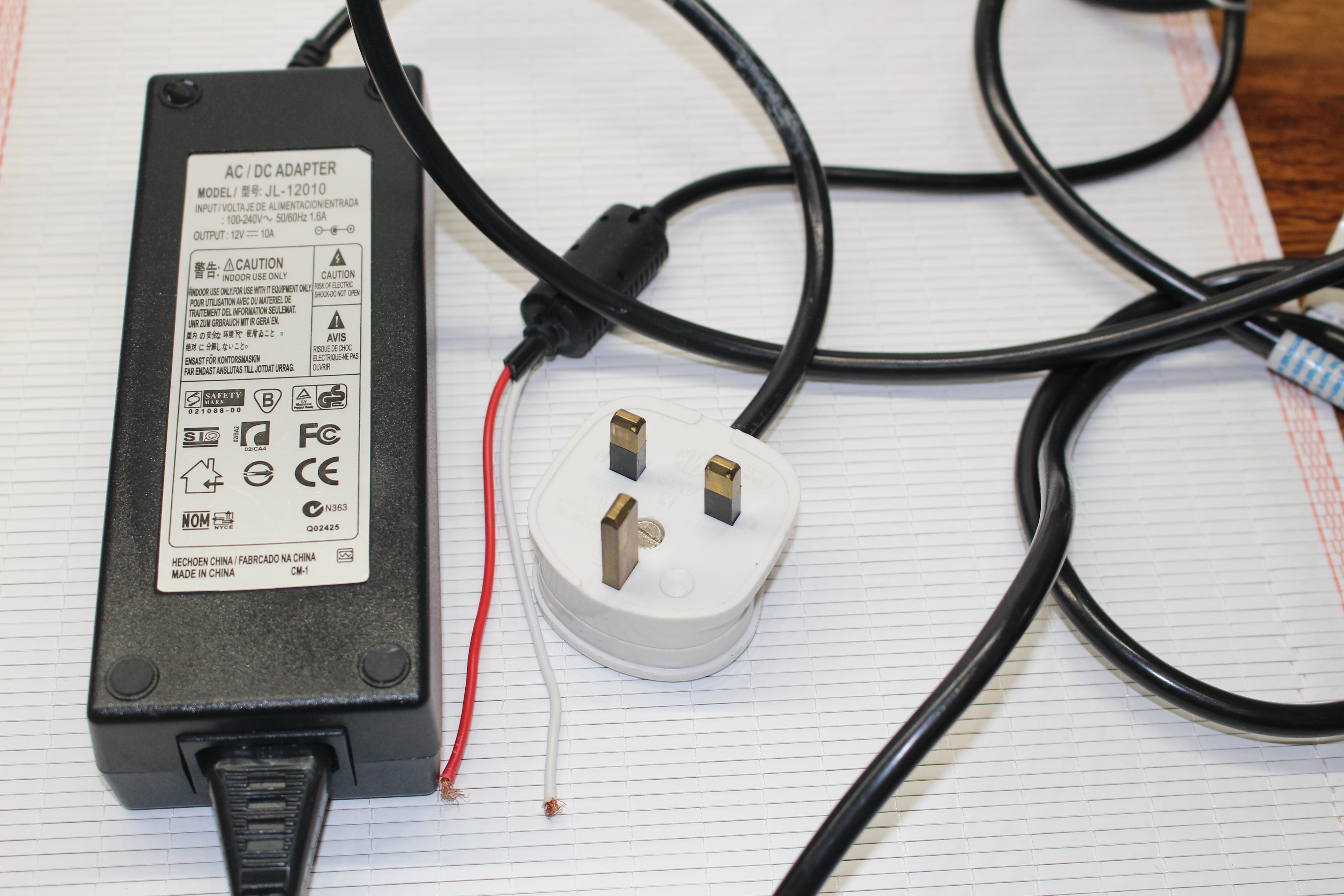
- 1x 12v 10a Power Supply
- 8x 12v 2a Solenoids
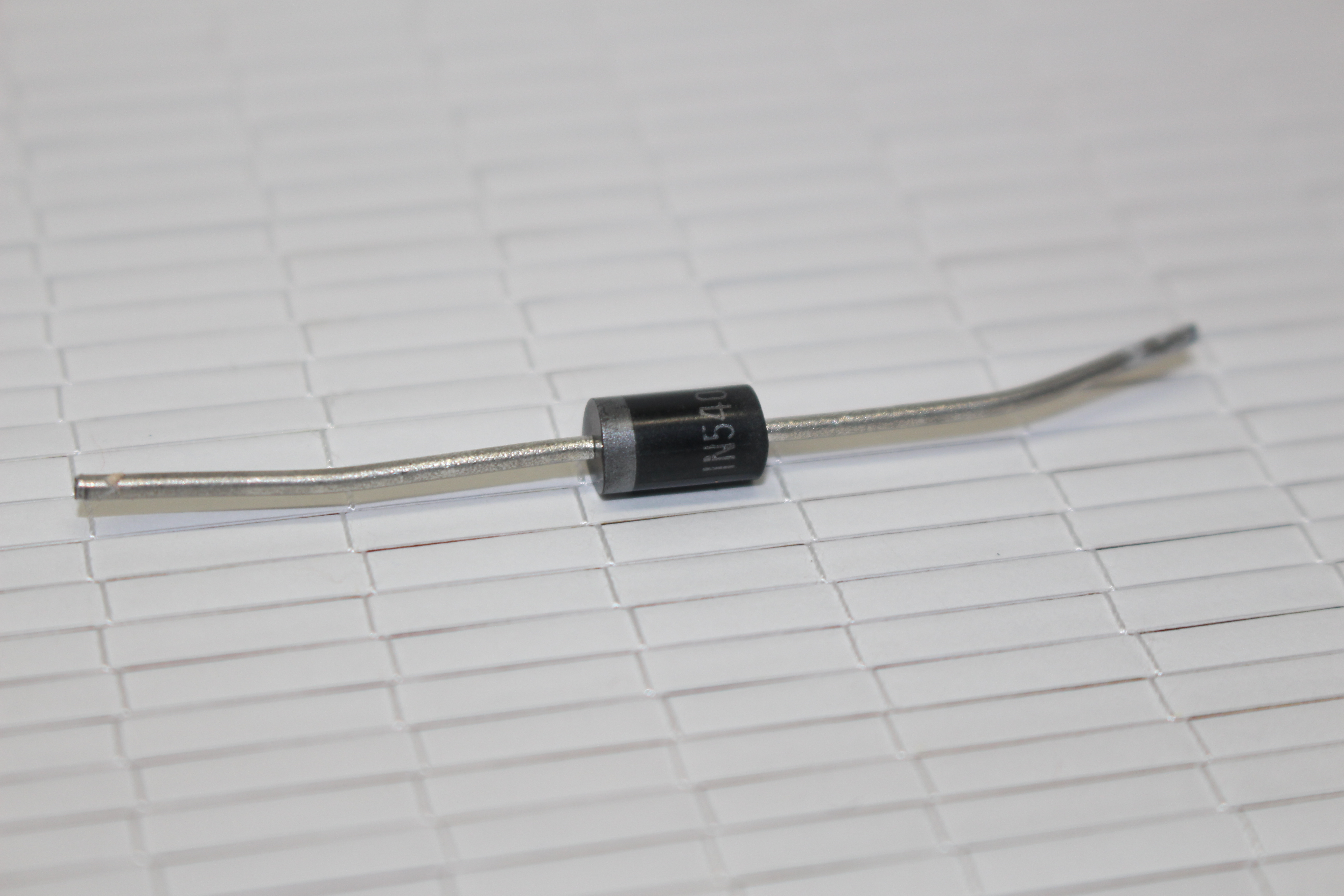
- 8x 1N5401 Rectifier diodes
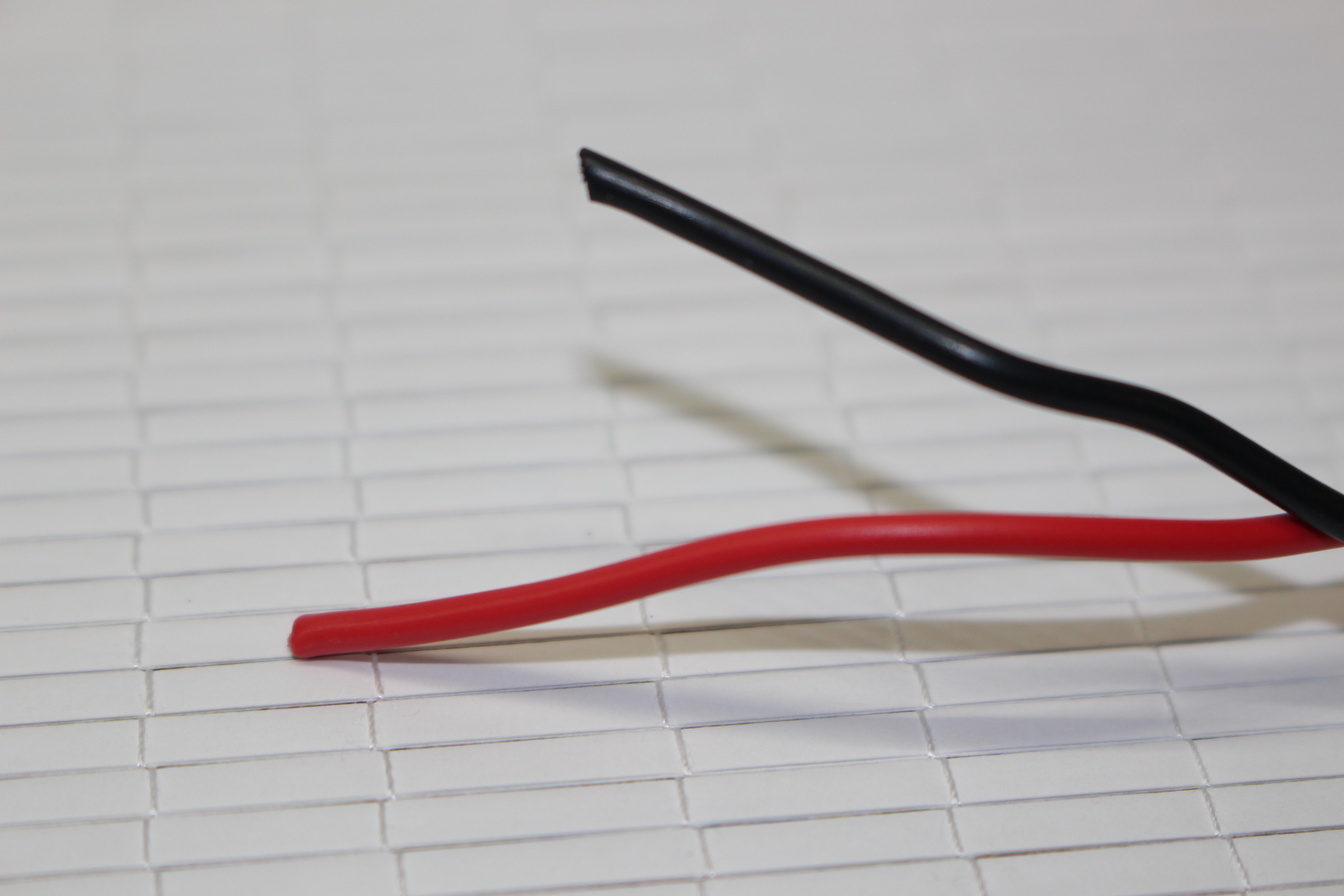
- 50cm of 0.5mm cable (I stripped the cores from some twin core cable as it was a cost effective way to get red, black and twin core), although you can just use 1 colour if you want. You may wan't to buy a bigger length depending on the housing you want to build.
You will also need the following tools:
- Wire cutters
- Wire strippers
- Small flat head screwdriver, about 3mm
- Depending on terminal strips you get, you may also need a small cross head screw driver
I have not listed any parts or tools to make the drums and any housing you wan't to put it in. I’ll show you how I made mine later, but as said before I’m leaving that part up to your imagination.
Wire Up the Pi to the Relay
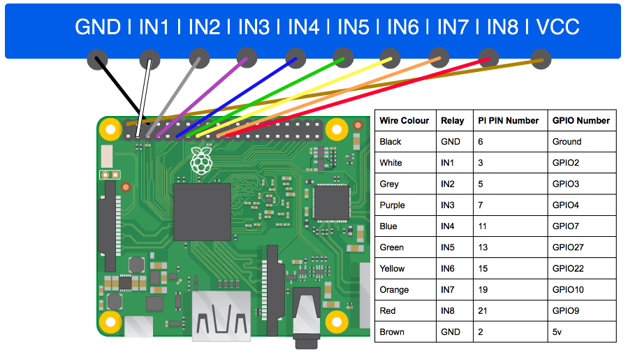
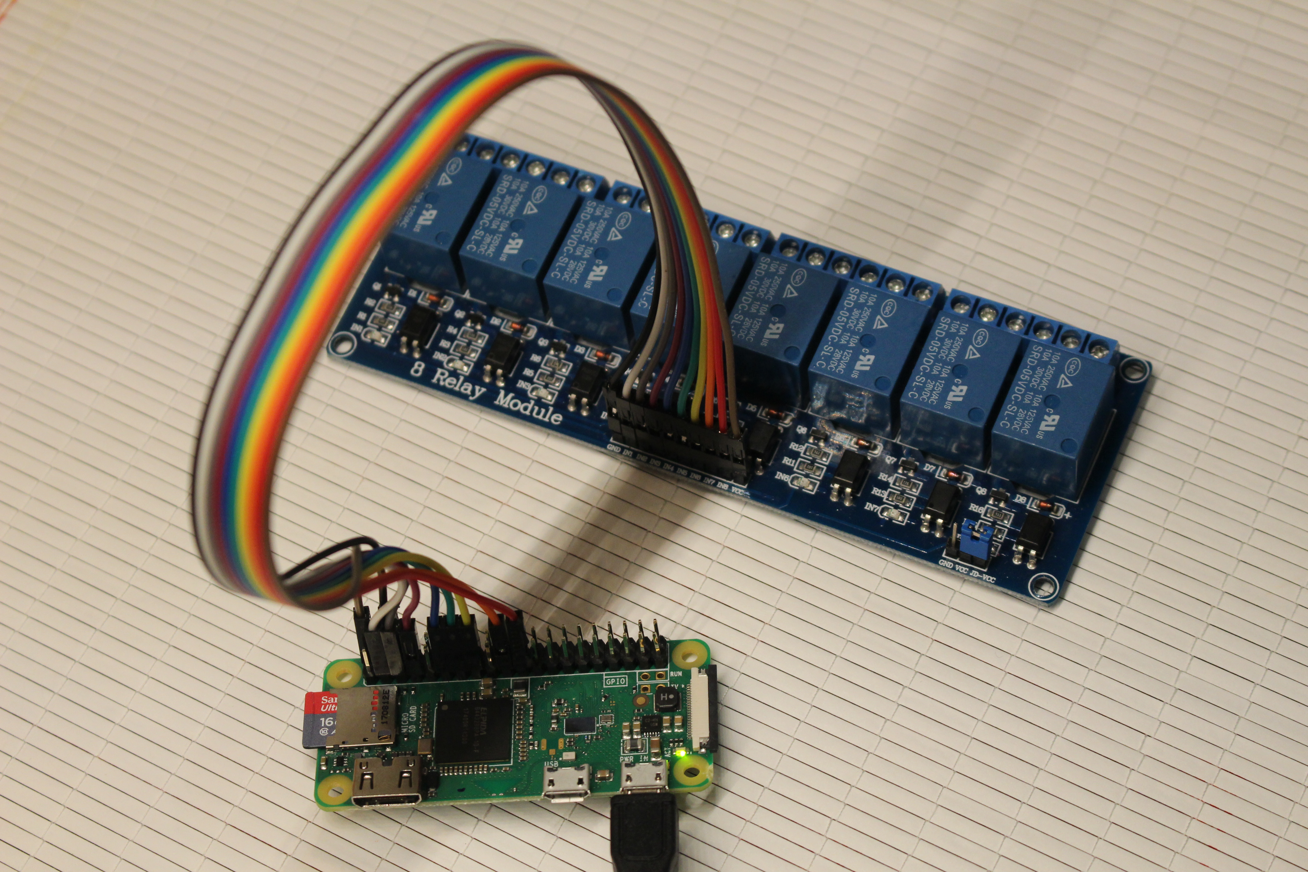
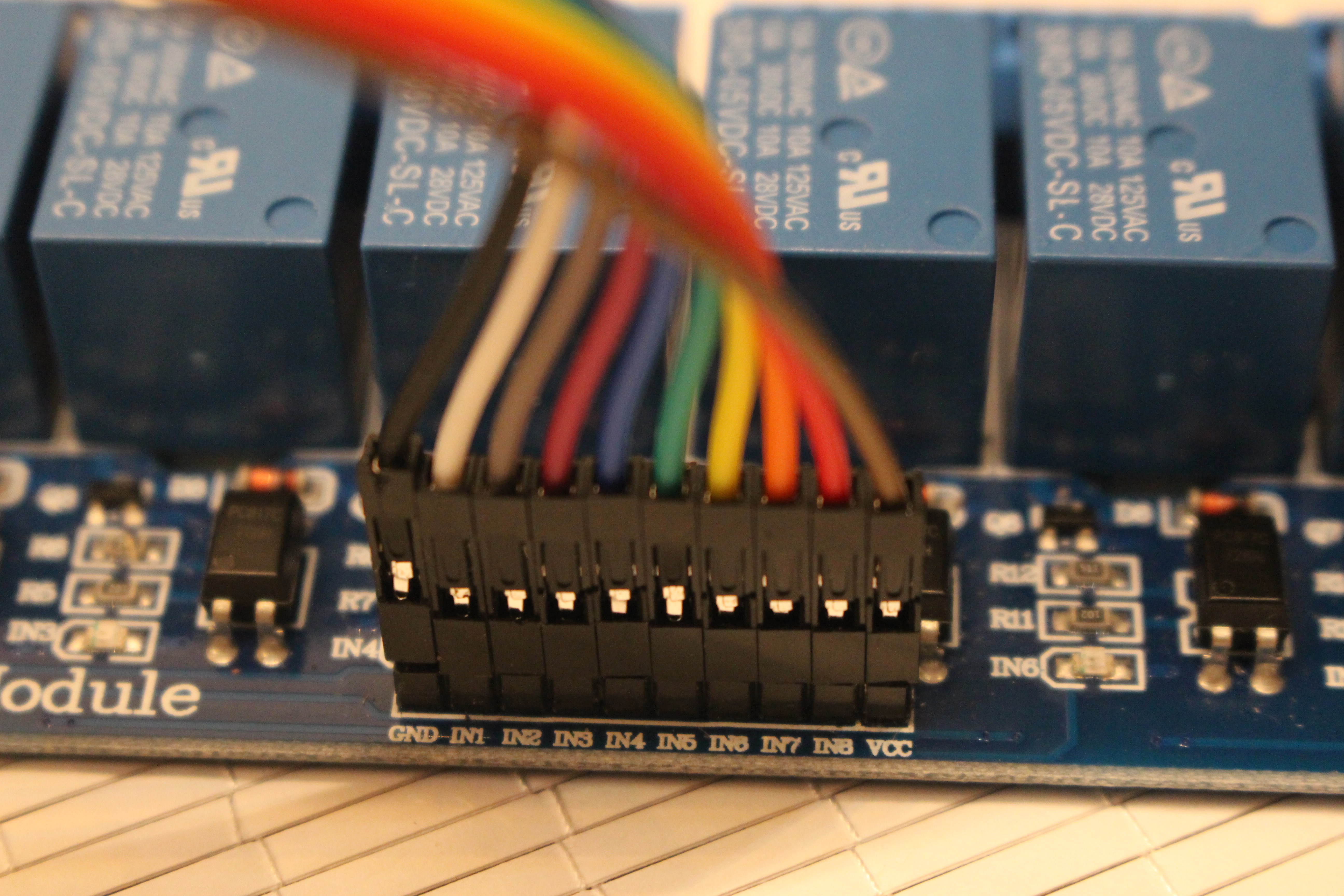
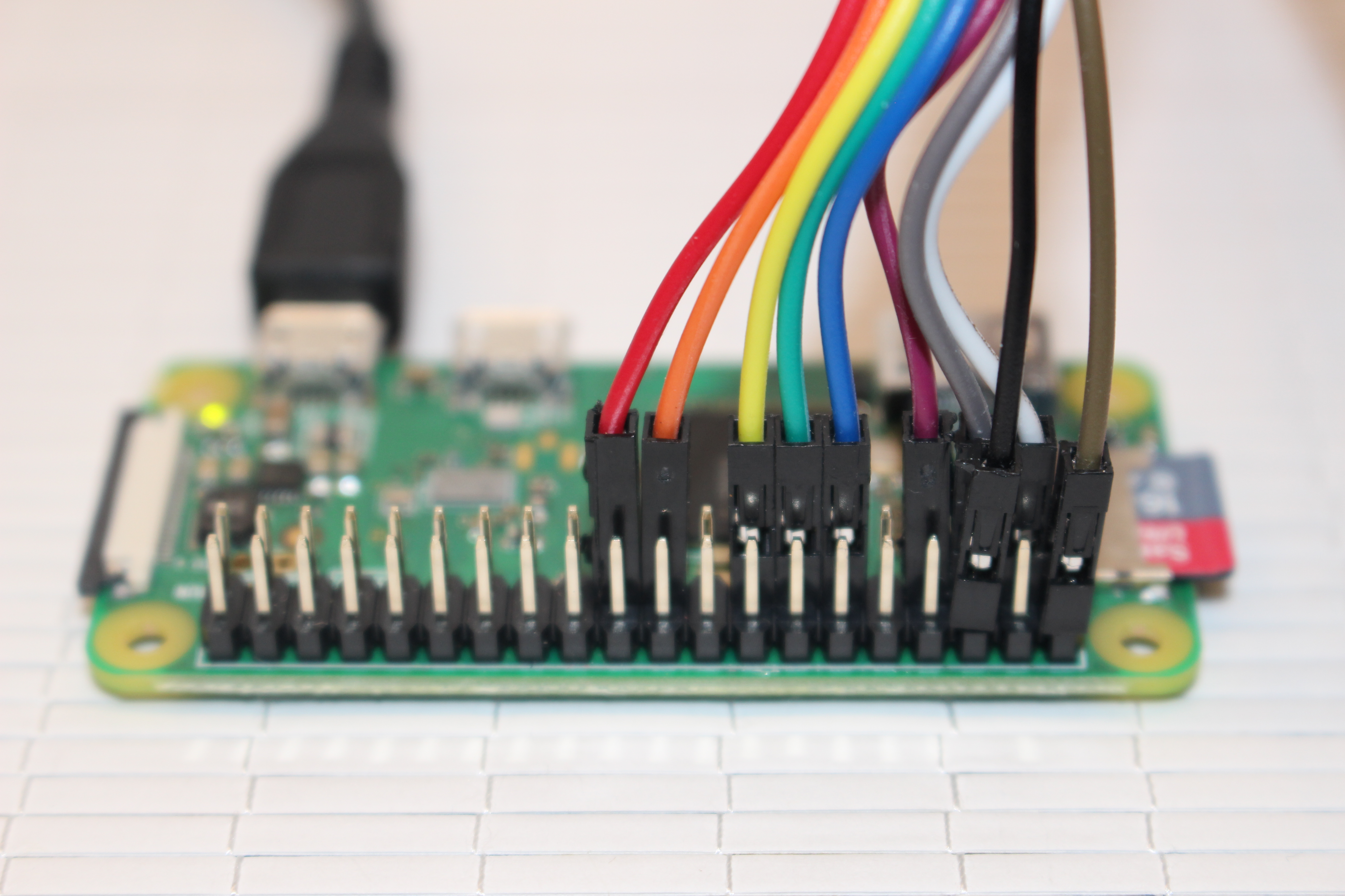
The maximum voltage provided by the pins on the Pi is 5v. We could buy 5v solenoids and power these directly from the Pi, but that would not give the big whack our drum machine needs. Therefore we are using a relay which lets us switch on and off a higher voltage circuit (in our case a 12v circuit containing our 12v solenoids) from our lower voltage GPIO circuit.
Our relay has 8 channels, this means we can switch up to 8 solenoids on and off independently. Each channel contains 4 connectors; 3 are used by the high voltage circuit which we will see later, and 1 which is an 'IN' pin on the lower voltage circuit which we will connect our Pi to. When the Pi's GPIO pin sends 5v on a given channels IN pin, the relay will switch on the corresponding 12v circuit.
On the low voltage side of the relay, there is also a GND (ground) pin which we need to connect to the PI's ground, and a VVC pin for the 5v power from the Pi.
With the Pi turned off, follow the diagram to connect the relay to the Pi using the jumper cables. You don't have to use the same colour jumpers, but it may help when following the images.
Lets Make Some Noise!
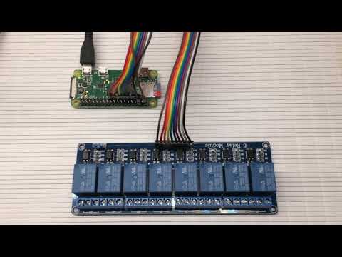
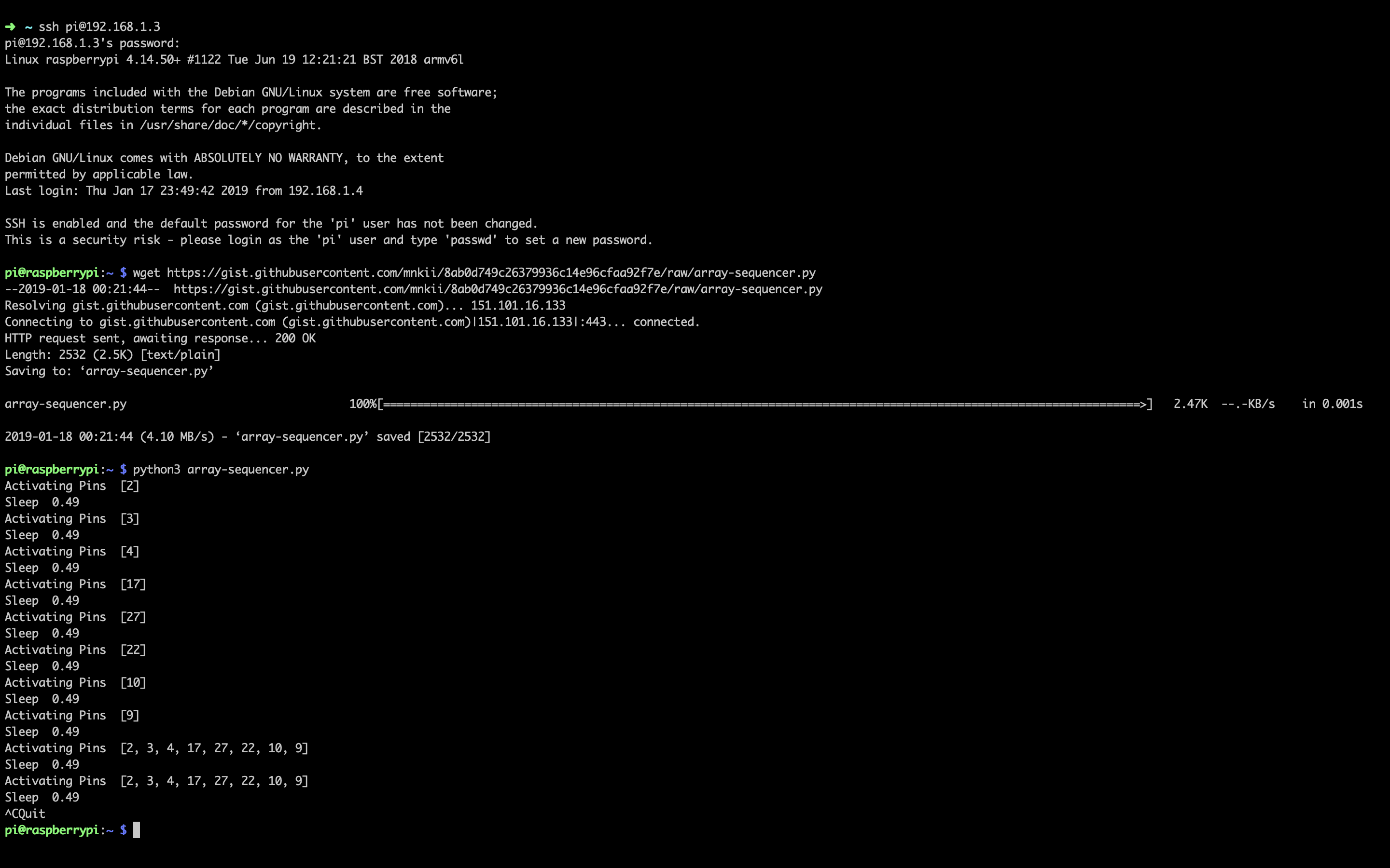
It may not be our fully fledged drum machine yet, but in this step we our going to make some noise, albeit clicks from the relay. We will introduce the python script to program drum patterns, this will enable us to test what we have done so far.
The script is available has a gist here.
Boot up your Pi, open up a terminal on the Pi and download the script by running:
wget https://gist.githubusercontent.com/mnkii/8ab0d749c26379936c14e96cfaa92f7e/raw/array-sequencer.py
You may want to look through the code and comments to get an idea of what it does, but lets get some gratification and run it:
python3 array-sequencer.py
If all goes to plan you should hear the contacts in the relay opening and closing and the light on the corresponding channel flash. Take a look at the sequence variable inside the script to get an idea what is going on - all channels will be triggered together, then each will be triggered individually. It will keep running until you exit the script by pressing Ctrl + C.
Before proceeding, it is a good idea to turn the Pi off again incase of any accidental short circuits when wiring things up.
Create the Positive Side of Our Circuit
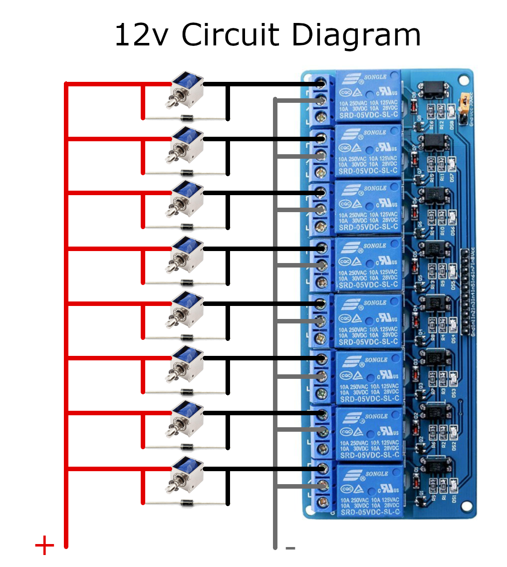
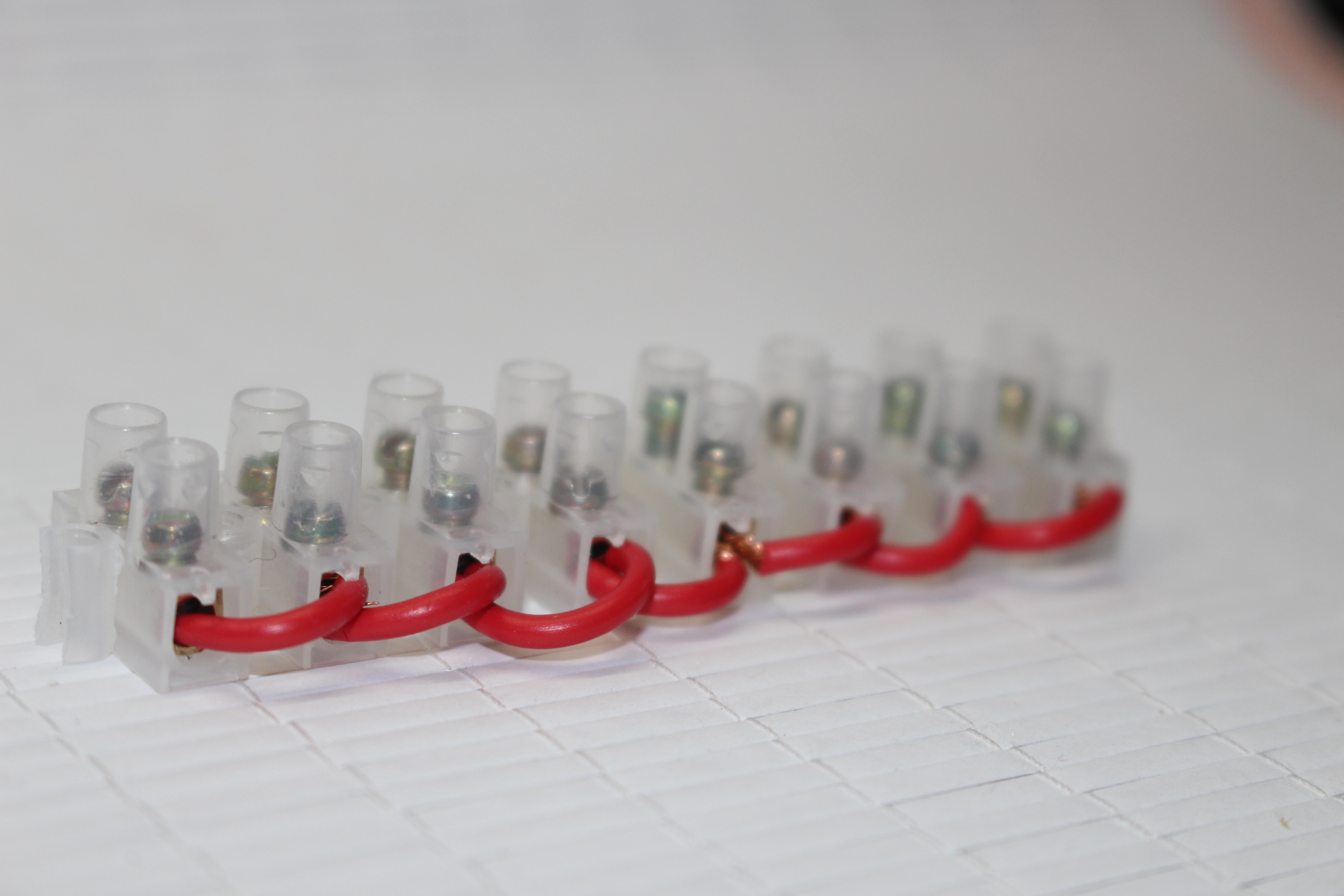
To power 8 solenoids with one power supply we will create a parallel circuit. You can see a diagram of the completed 12v circuit, but we are going to take go through it step by step.
You could use a breadboard or perfboard, but I opted for terminal strips as they are cheap, hold wires tightly, and I also didn't own a soldering iron when creating this.
Effectively, we need to connect all solenoids, and a diode for each solenoid (more on diodes later) to the 1 positive wire of our power supply.
Using the cutters, cut own the terminal strip so you have a block of 8 pairs, cutting at the plastic bit which connects two blocks together. Be careful to not trim any metal.
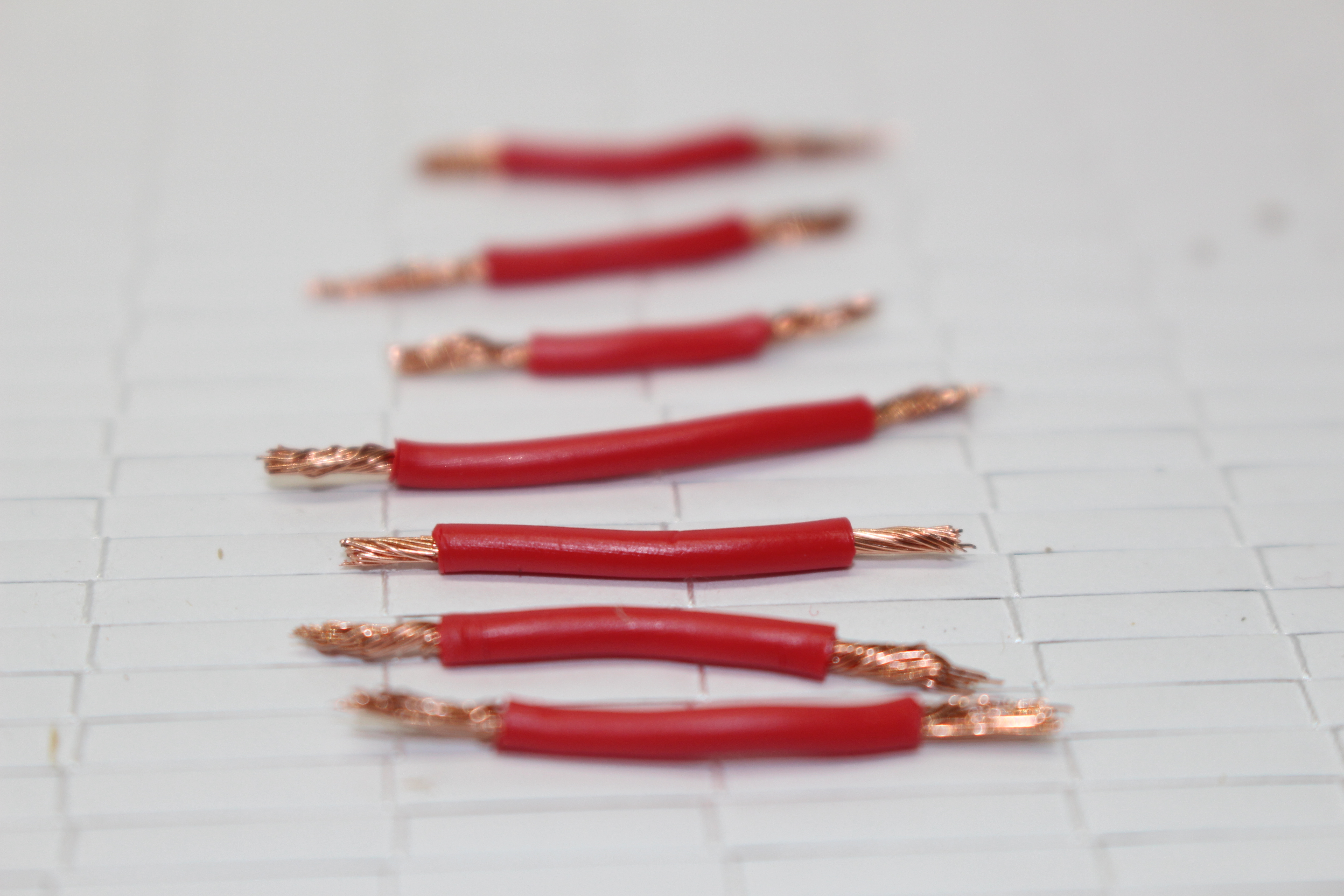
We now need to join up all the terminals down one side of the strip. Use the cutters to cut 7 pieces of red wire about 35mm long, then use the wire strippers to remove around 5mm of insulation from each end of every wire.
Now use the wires to daisy chain all the terminals together along one side of the strip, holding the wires in place using the screws. The first and last screw will only have 1 wire, while the rest will have 2.
Add the Solenoids and Diodes
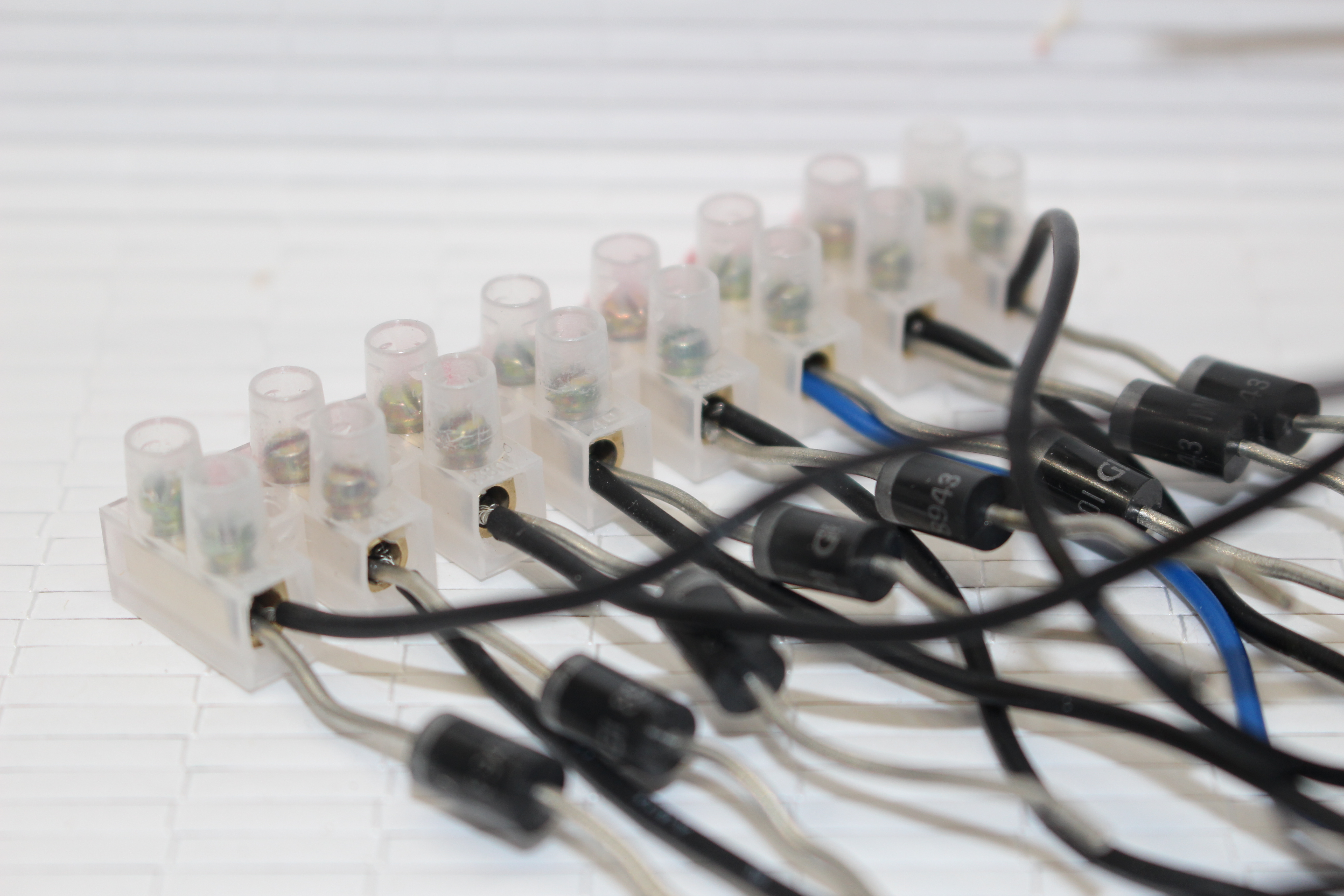
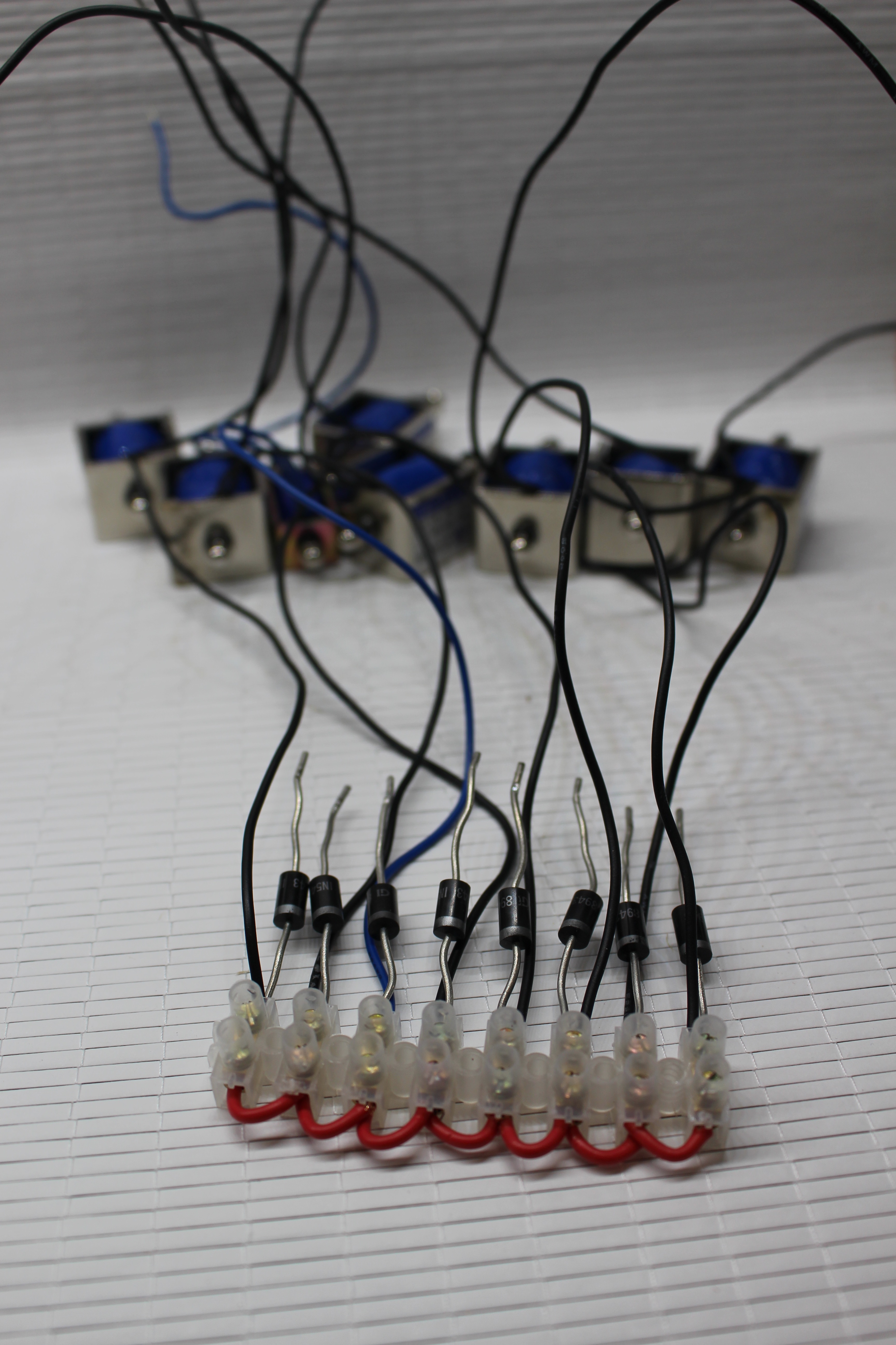
As solenoids are electromagnets, diodes are recommended to protect your circuit from flyback (you can read in-depth about that here). Therefore we will give each solenoid its own diode to protect our relay.
On the opposite side of the terminal strip to which you wired together in the previous step, start with the first hole. Insert 1 wire of the solenoid, then add in and one end of the diode into the same hole. As diodes only allow the flow of current one way, make sure the silver stripe on the diode is towards the terminal strip. Tighten the screw to hold them in place. Repeat the process for the remaining 7 holes.
One of the solenoids I received was faulty, so at the time of taking the pictures I swapped it out for a lower amp model which had blue wires.
Connect the Negative Terminal Strip to the Solenoid and Diodes
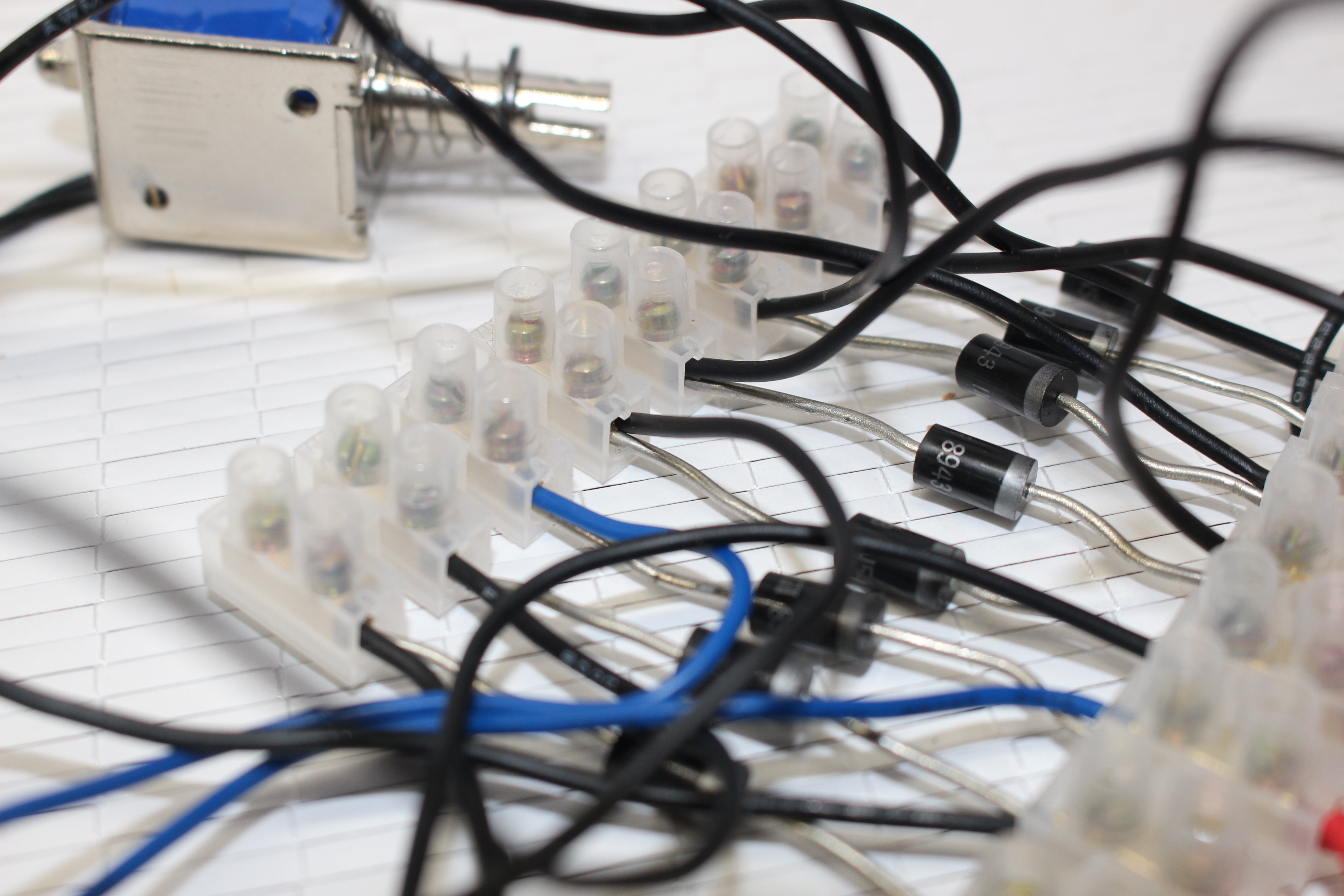
As we did with the positive side, get 1 terminal strip and cut it down so you have another strip of 8 pairs . Screw in place the diodes and solenoids to this terminal strip so it mirrors the plus terminal strip.
Create the Relay Connecting Wires
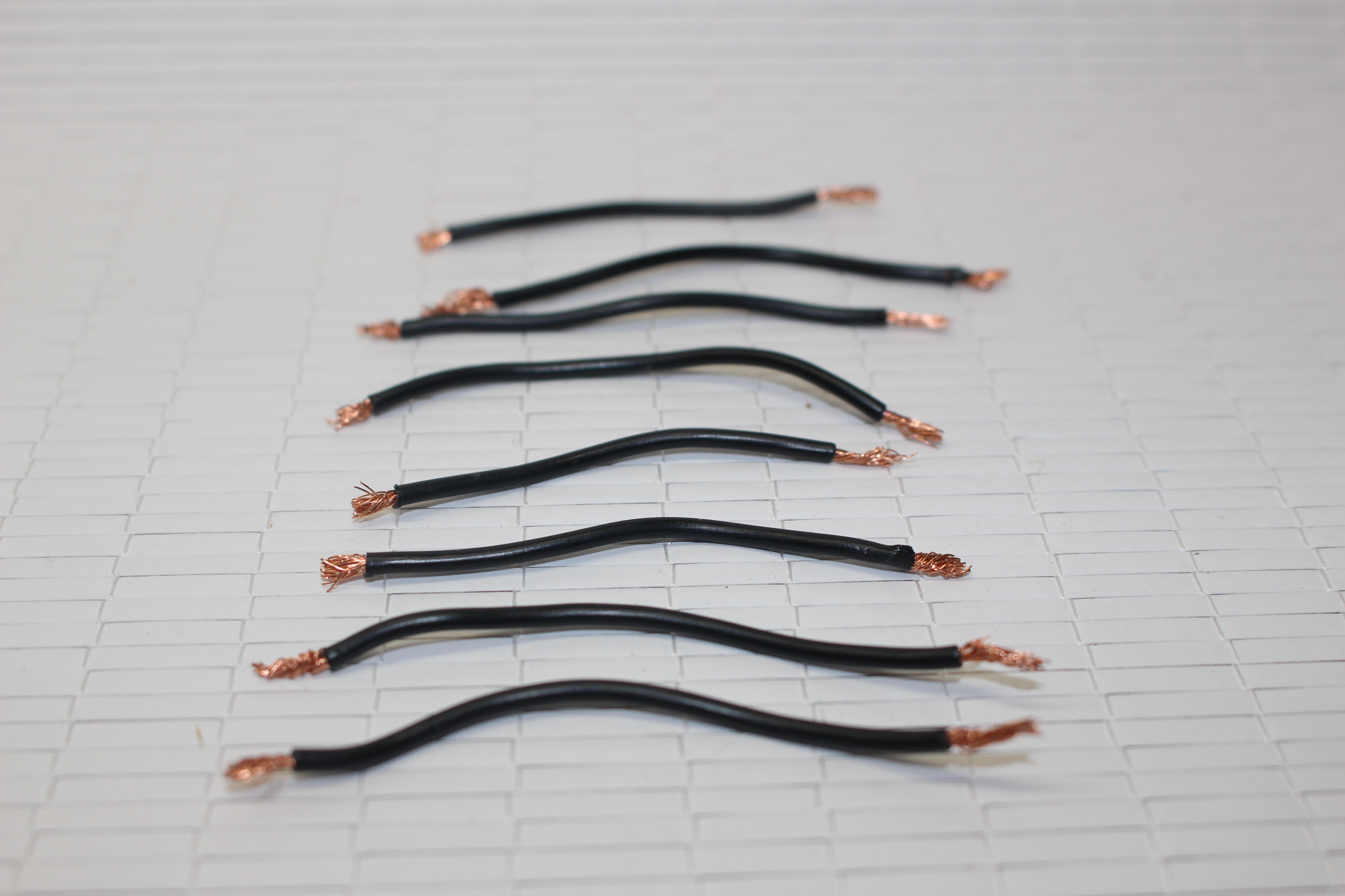
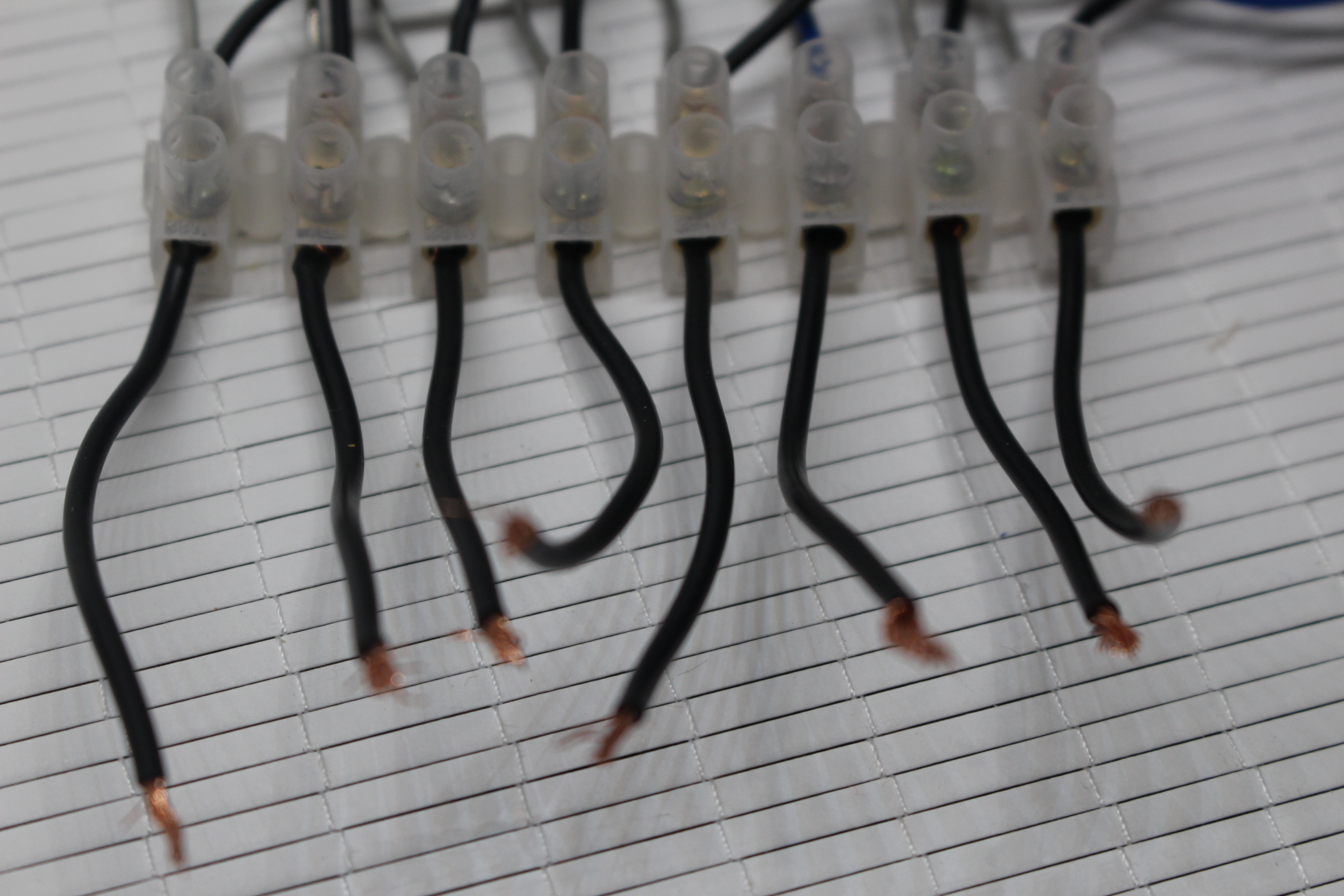
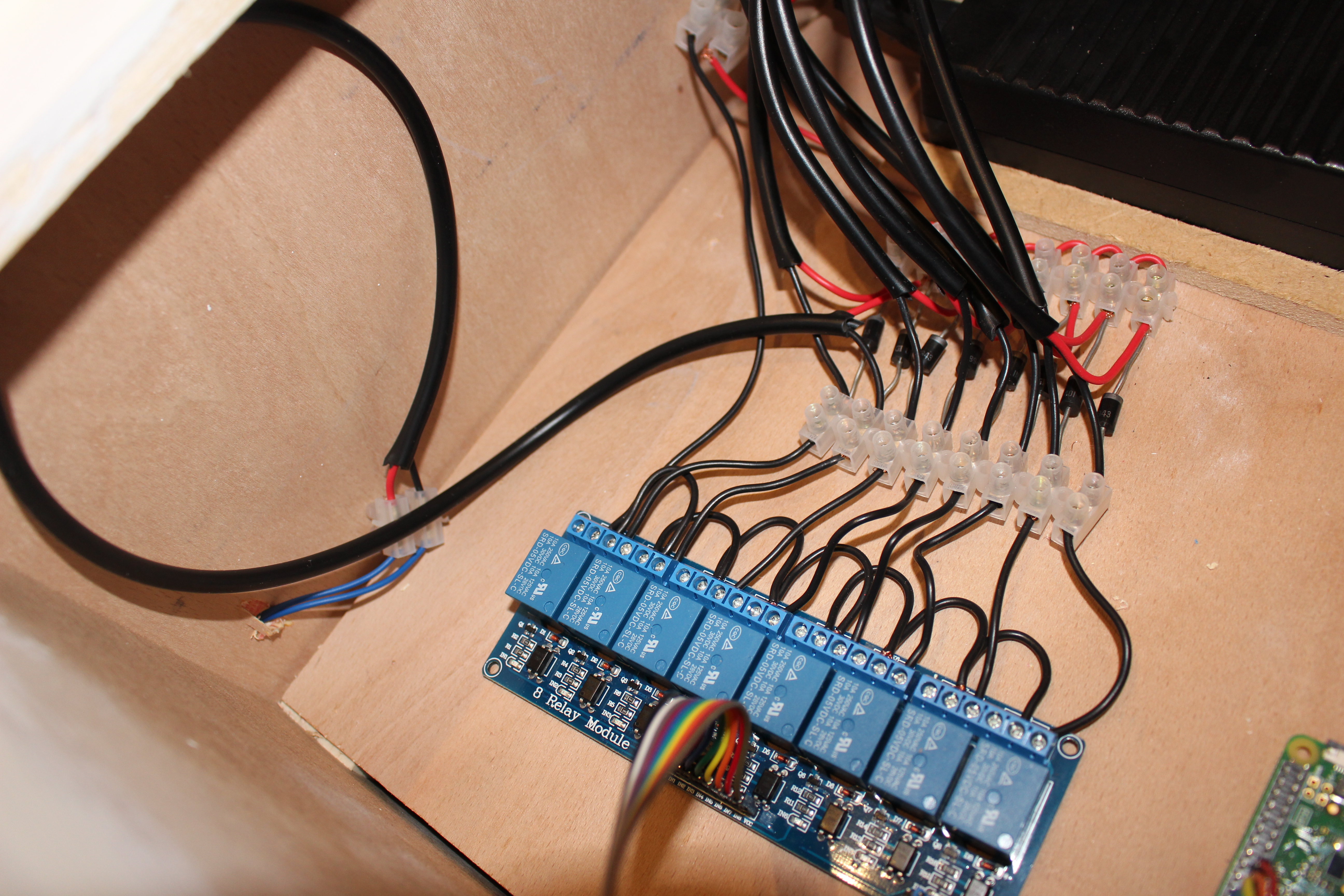
We are nearly ready to connect the relay, but first we need to something to connect it with. Cut 8 pieces of black wire about 70mm long, then strip around 5mm off of each end. Attach each wire to the 8 remaining connectors on the negative terminal strip.
Wire Up the Relay Common Connectors
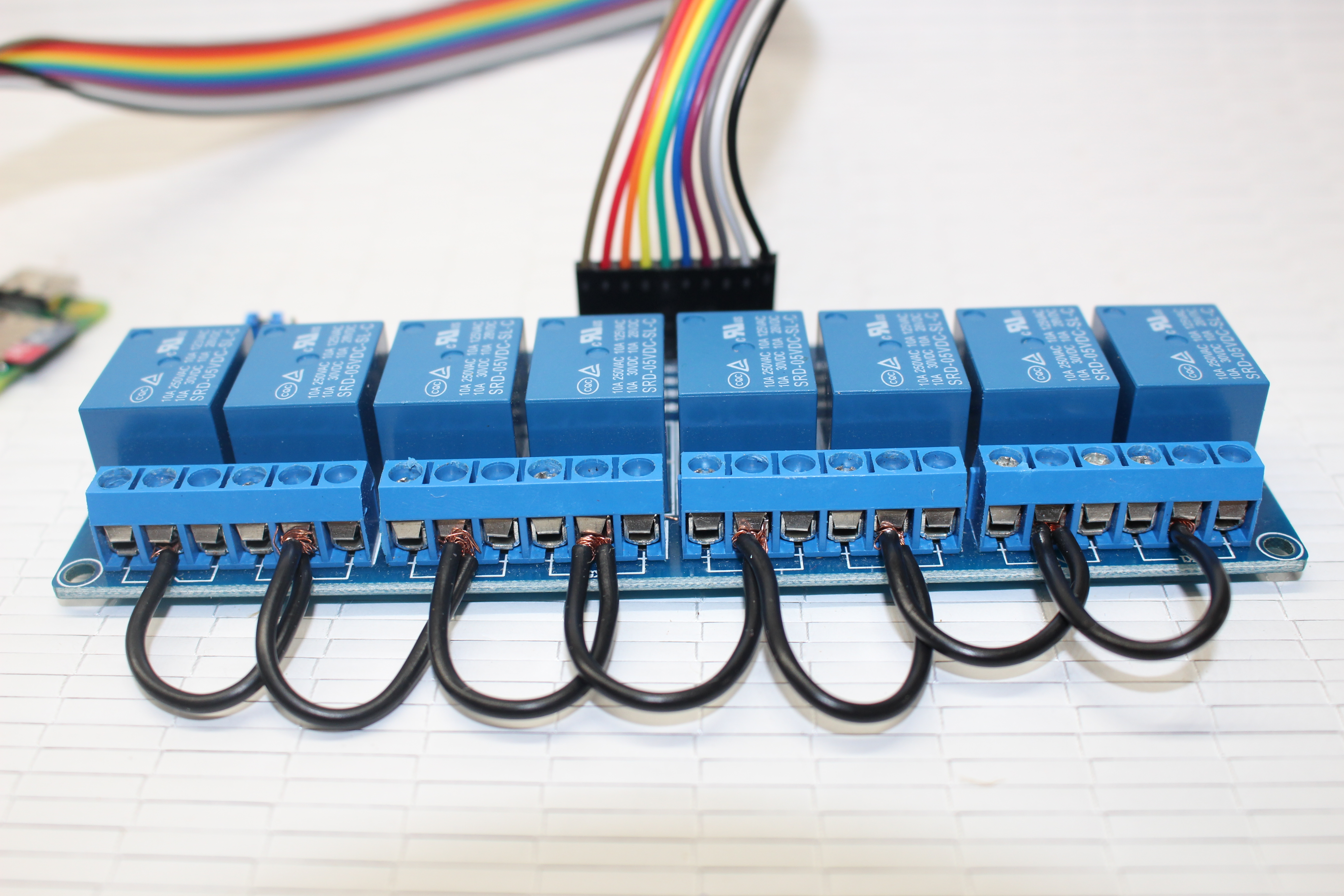
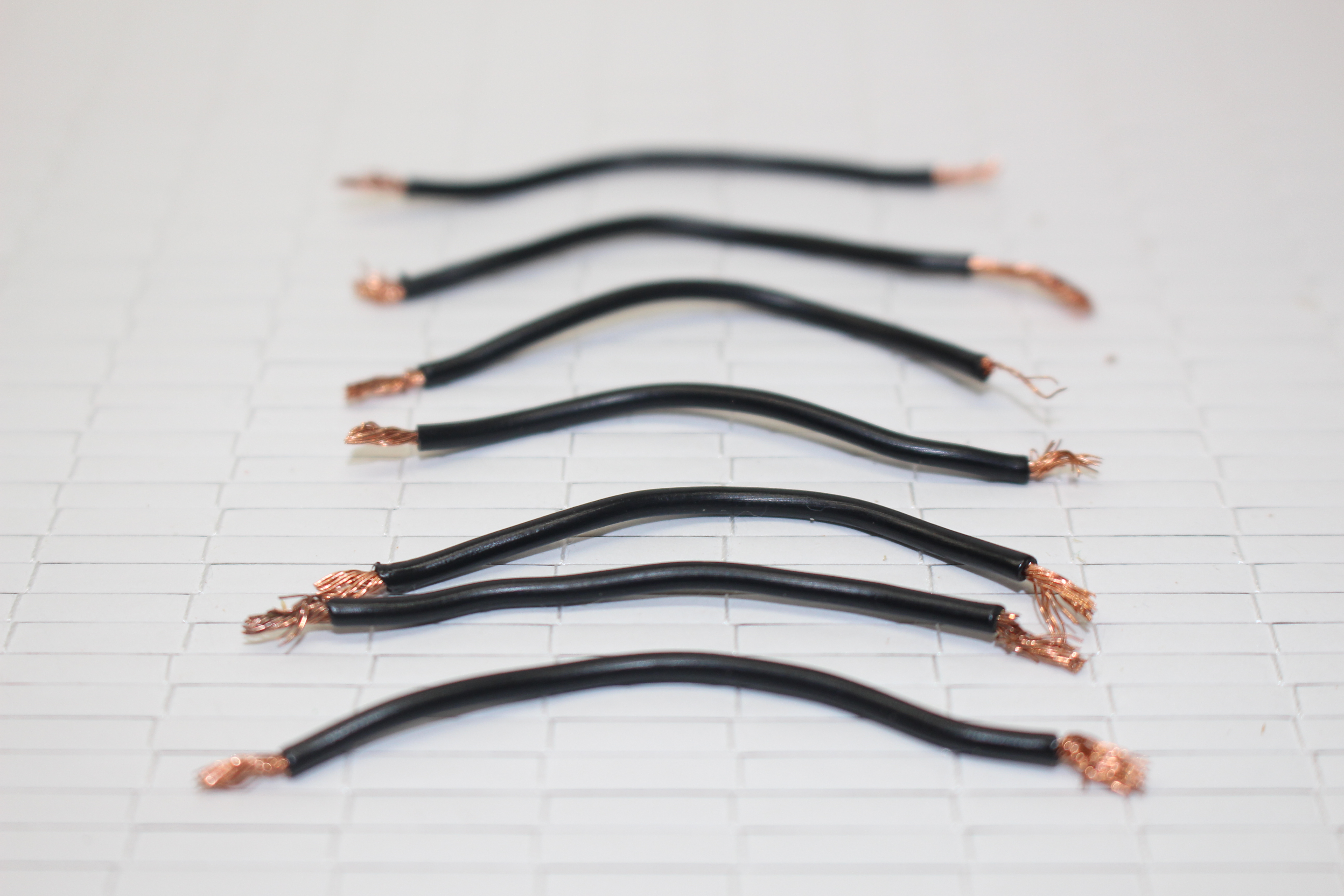
Take a look at the relay holding the side connected by the jumpers to the Pi away from you. Each channel has 3 contacts, from left to right they are called normally open (NO), common (COM) and normally closed (NC). We only want our solenoids to turn on when there is a high voltage on the channels IN pin, so will use the normally open contact. If we were to use the normally closed contact instead the opposite would happen - the solenoid would be on until a high voltage is sent on the IN pin. We will also use the common contact to complete the circuit.
As this is a parallel circuit, we will daisy chain all the common contacts on the relay. Cut 7 pieces of black wire about 60mm long and strip 5mm off of each end. Work along the relay connecting all the COM contacts (the middle of each set of 3) together. The first and last will only have one wire, the rest will have 2.
Connect the Relay to the Rest of Our Circuit
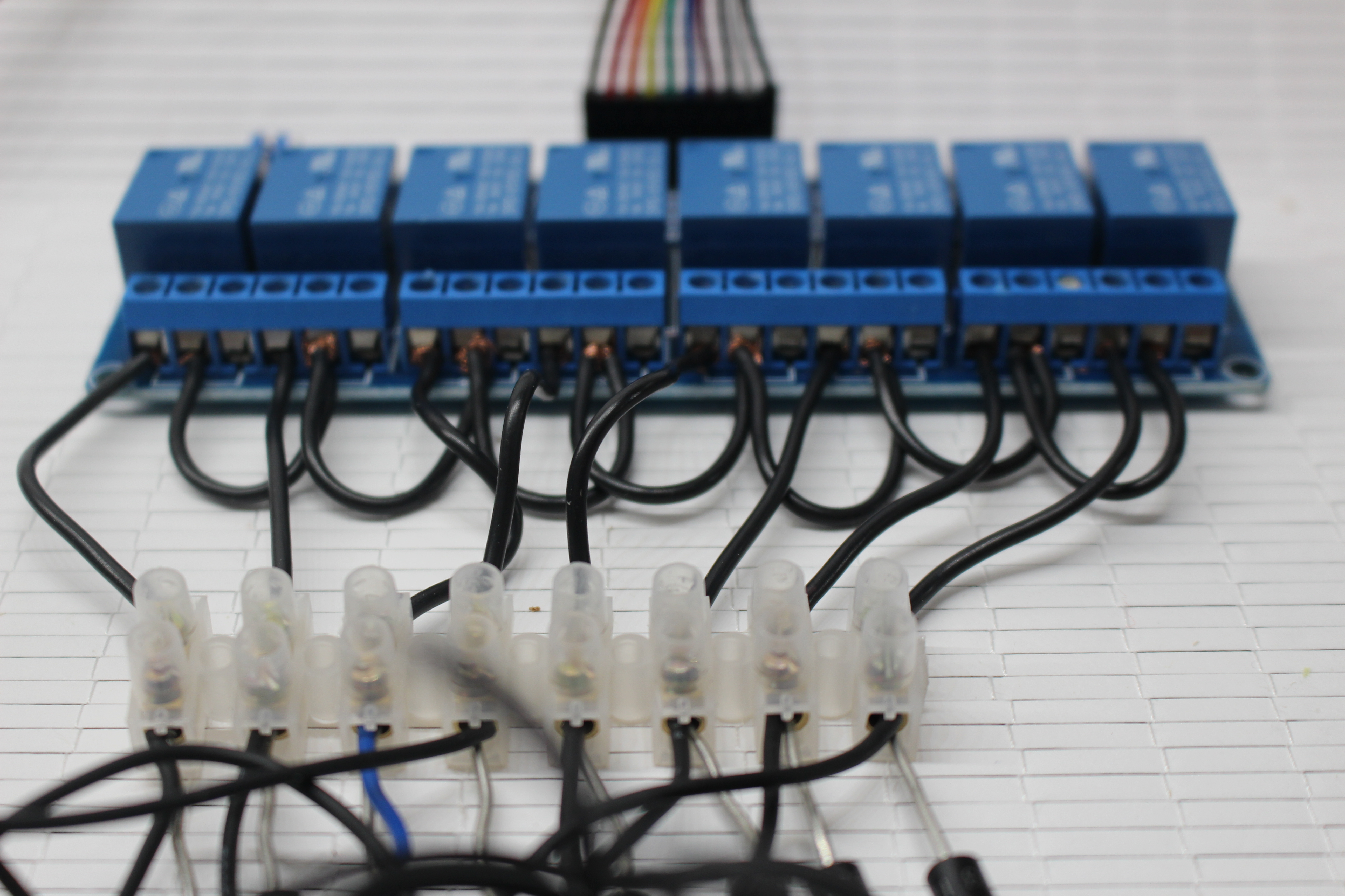
Now its time to connect the relay to the rest of our circuit. Take the unattached end of the black piece of wire from one end of the negative terminal strip, and connect it up to either the first or last of the normally open (NO) contacts on the relay. Repeat this for the 7 other pieces of wire, connecting each wire to the next NO contact.
Connect the 12v Power Supply
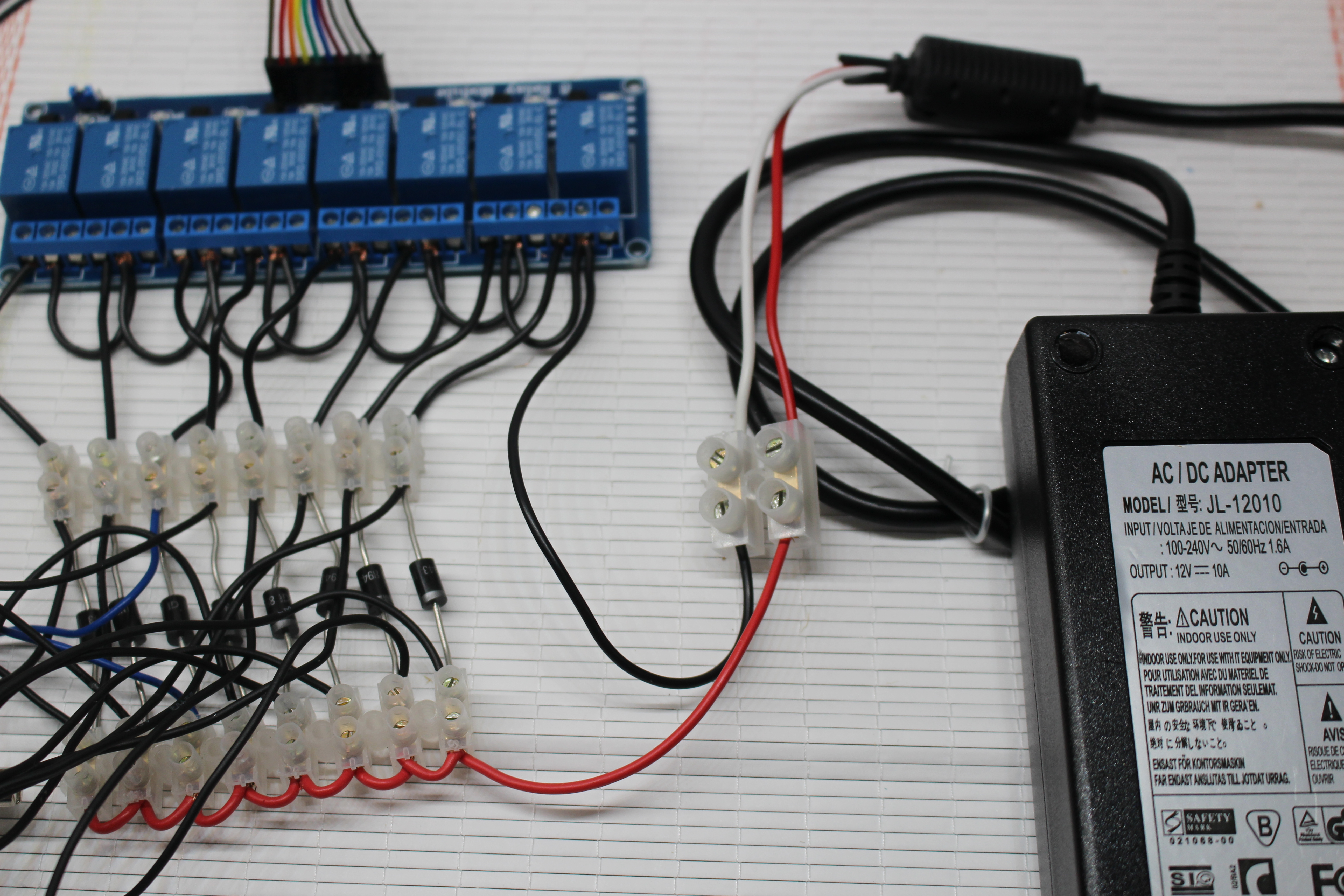
Firstly, to avoid any shock, make sure your power supply is turned off and unplugged from the mains.
My power supply came used from eBay with the 12v male plug already stripped off. Presuming yours still has the plug, you can either buy the matching female DC connector, or cut the plug off and strip it back to the 2 wires like mine. Either way, you need to end up with 2 wires, the red (positive) and probably white (negative). Connect the positive wire of the power supply to the first contact on the positive terminal block, and the negative to the first common contact on the relay. To make this easier, I used around 150mm of red and black wire with the ends stripped to go between the connections, and connected using a terminal strip.
Fire It Up
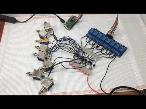
With your power supply still turned off, give all your connections a quick check over. Once happy, boot up the Pi again. Run the script from step 3 again:
python3 array-sequencer.py
Your solenoids won't move yet, but you should hear the relay click and illuminate just as you did in step 3. Terminate the script (Ctrl + C), and now it is the moment you have been waiting for - turn on the power supply! Run the script again, your all dancing solenoids should now come to life. Good work!
I was unlucky - as you can see in the video another one of my solenoids was not working, but this was my fault as I previously damaged one by over tightening a fixing bolt.
Editing Array-sequencer.py
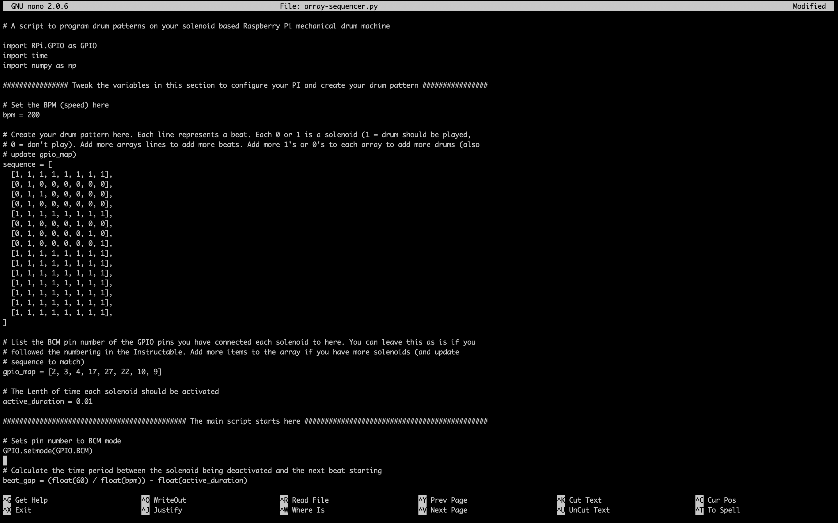
Take a bit of time to play around with array-sequencer.py. Use your favourite editor (nano, geany etc) to make changes to the script. Try doing the following and re-running the script after each change to see its effect:
- Change the bpm variable from 120 to another number, say 200 to increase the tempo.
- In the sequence variable, change some 0's to 1's to play more drums.
- Duplicate the last 3 lines before the closing square bracket in the sequence variable to add more beats to the loop
Install the Drum Sequencer
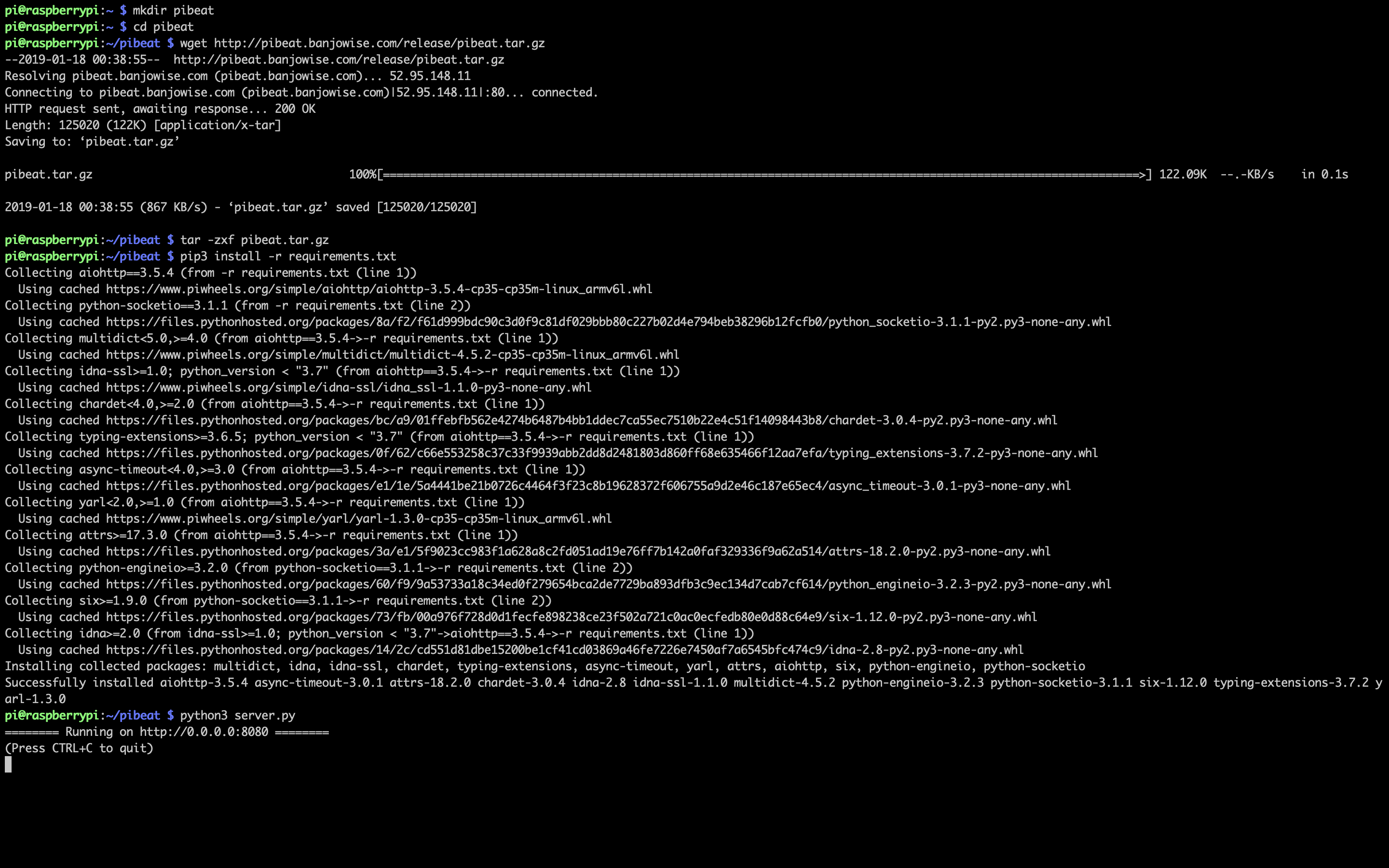

Now this is when things get really fun, we are going to install the sequencer onto your Pi. This is going to give us a web interface which lets Python trigger the GPIO pins over web sockets.
The source code is available in Github here, but presuming you followed the wiring in the Instructable we can download and run the precompiled version. Open up a terminal on your Pi, and run the following
# Create and navigate into a directory for our project
mkdir pibeat
cd pibeat
# Download the source code
wget http://pibeat.banjowise.com/release/pibeat.tar.gz
# Extract the files
tar -zxf pibeat.tar.gz
# Install the python requirements
pip3 install -r requirements.txt
# Run the web server
python3 server.py
In the output, if all is successful you should see the following output:
======== Running on <a href="http://0.0.0.0:8080" rel="nofollow">http://0.0.0.0:8080 </a> ========
(Press CTRL+C to quit)
Find you Pi's IP address. Open up a web browser, then enter the IP followed by :8080/index.html (this is the port the application is listening on followed by the filename) into the address bar. For example, if your Pi's IP address is 192.168.1.3, enter 192.168.1.3:8080/index.html into the address bar. The drum sequencer will appear.
Hit the play button and your drum machine should start playing. Play around with the sequencer until your heart is content.
As long as there is a network route to your Pi, you can access the Pi's web interface from any device - try it from your mobile or tablet.
Building Your Drums and Housing
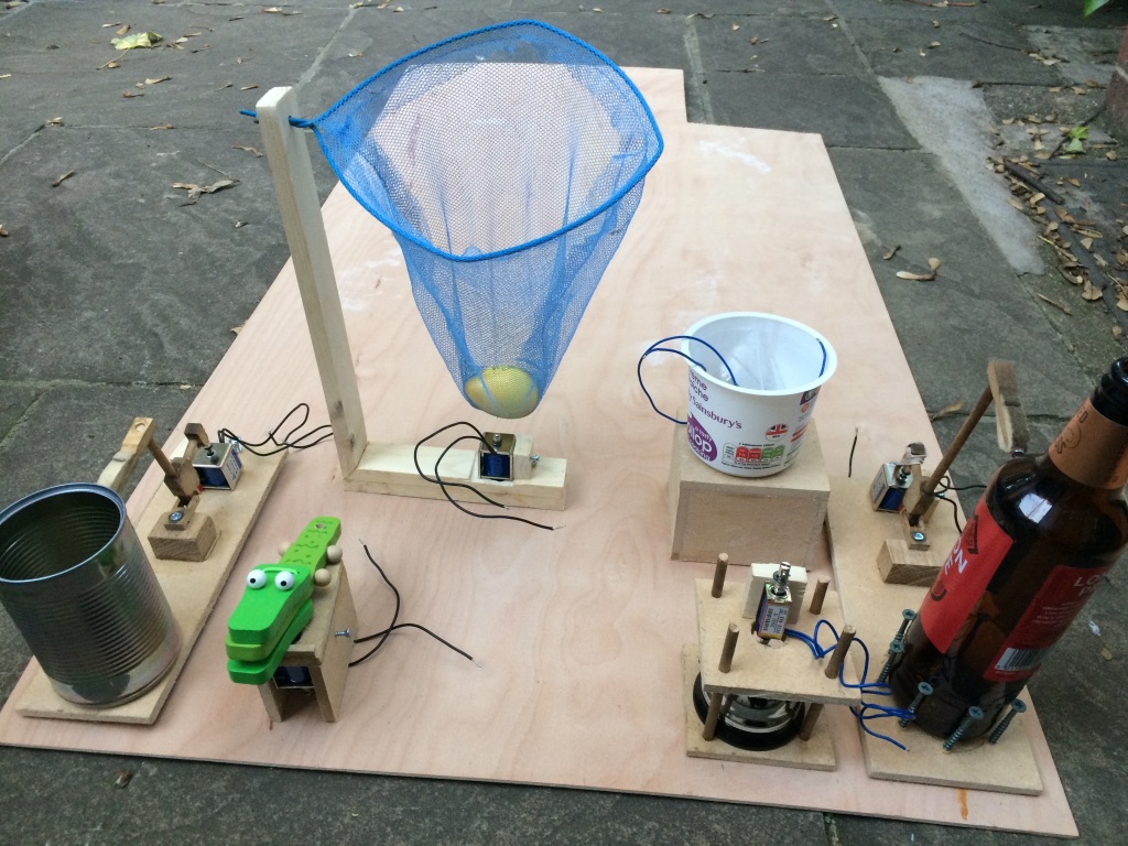
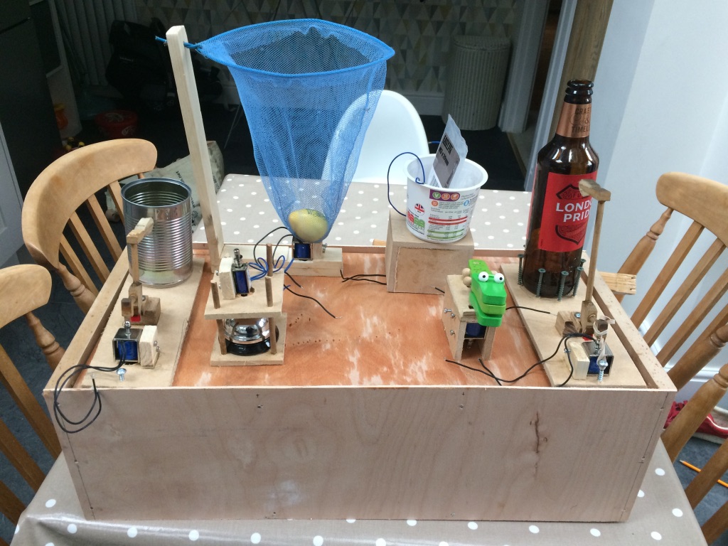
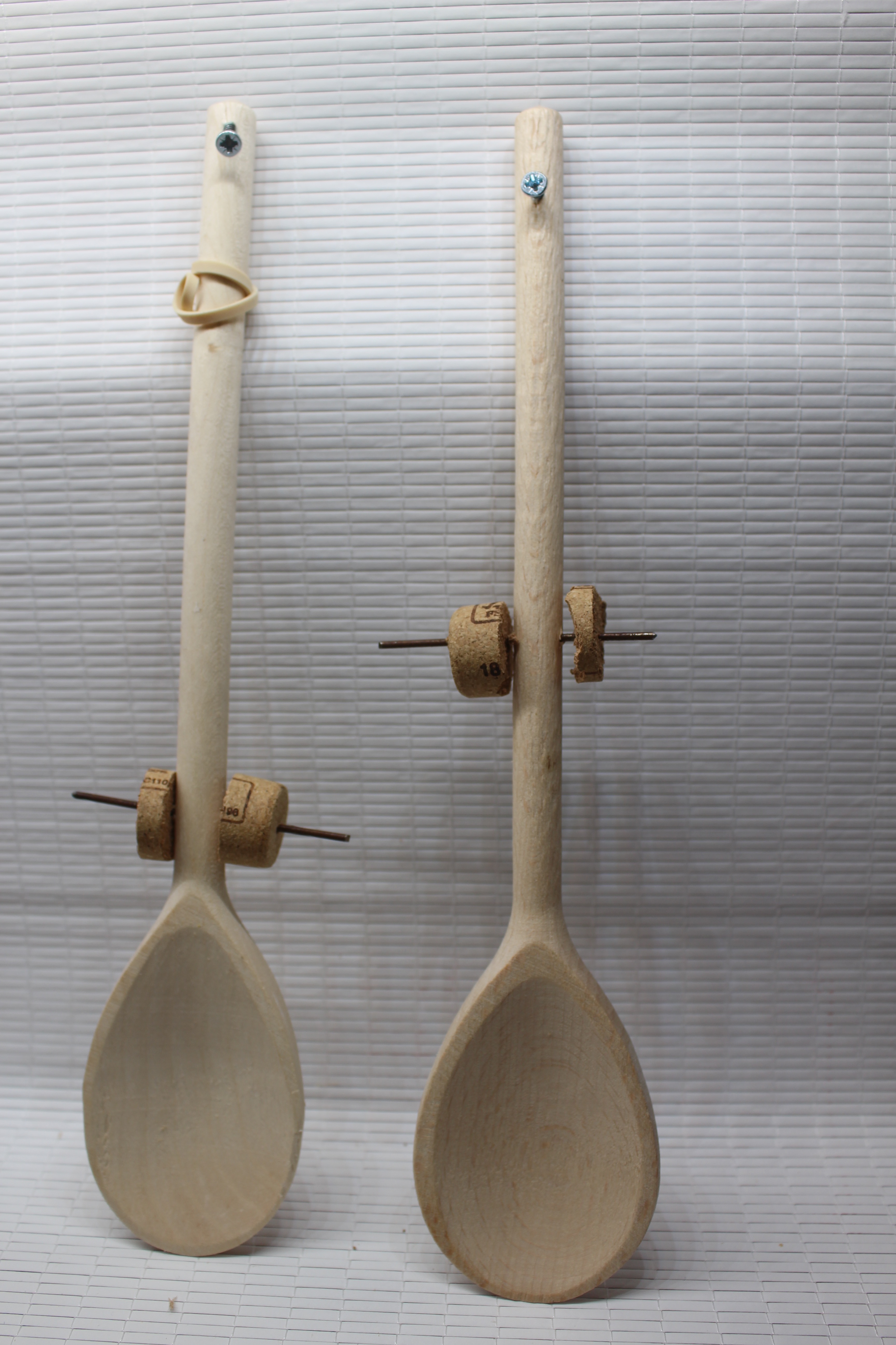
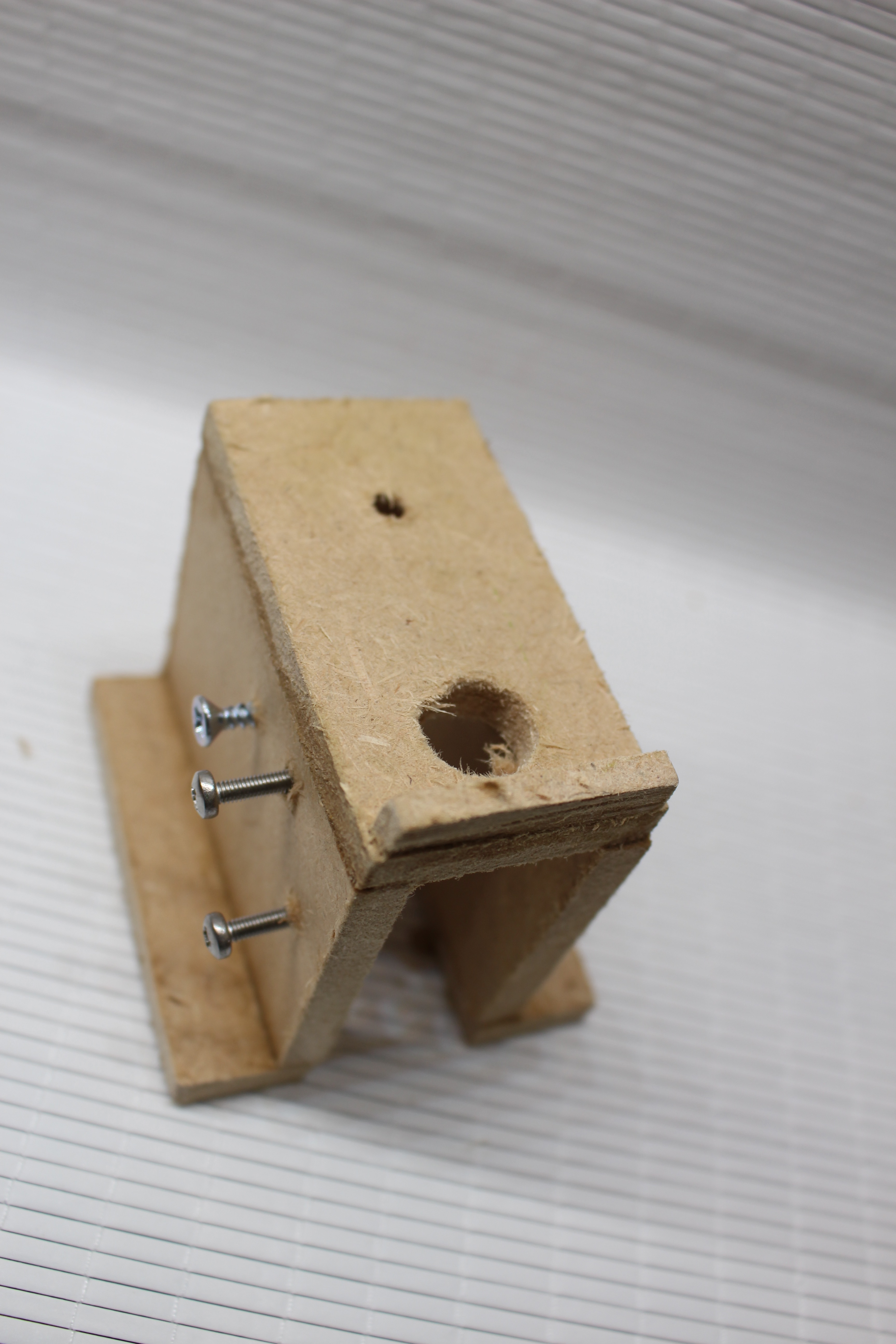
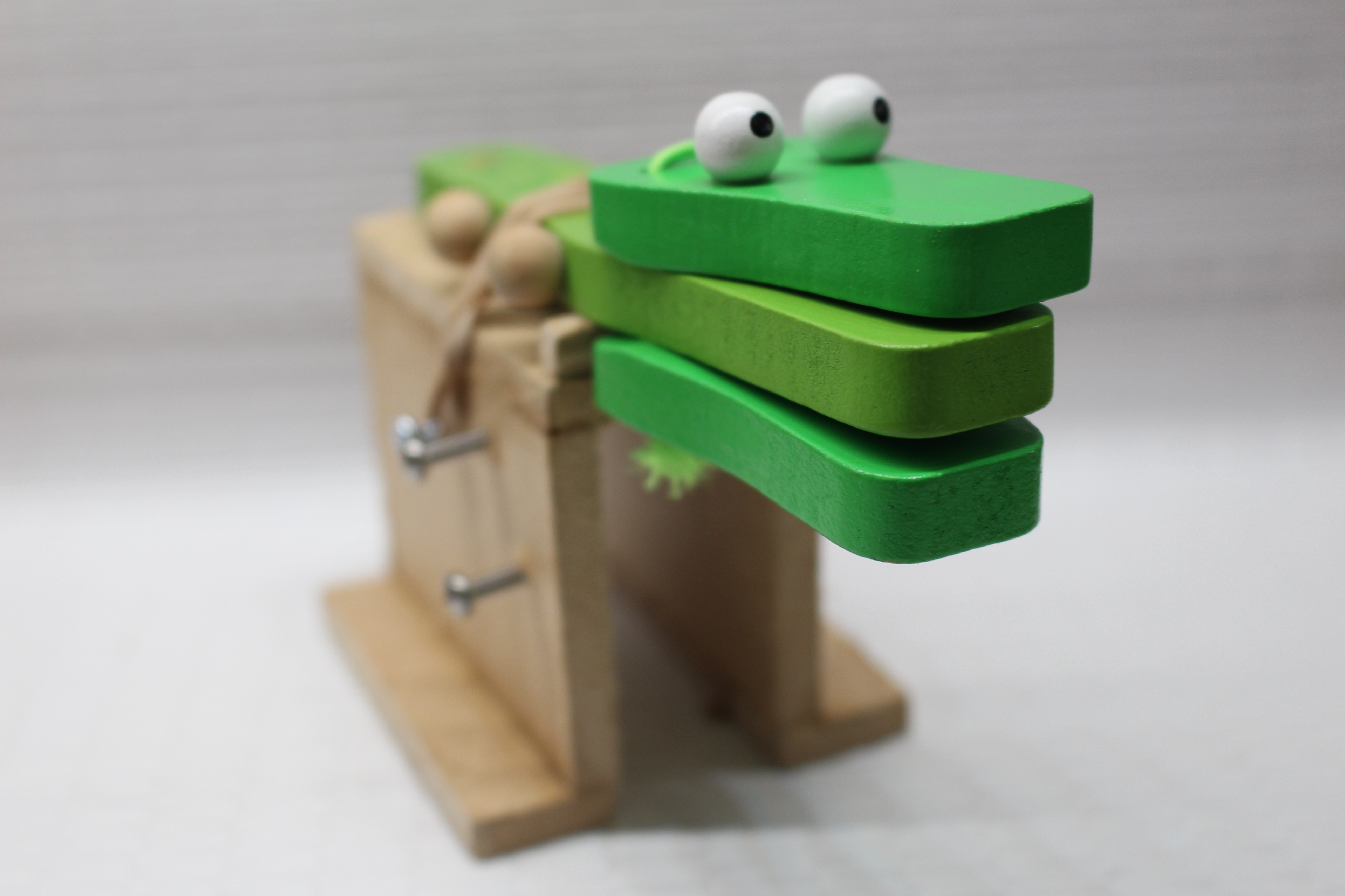
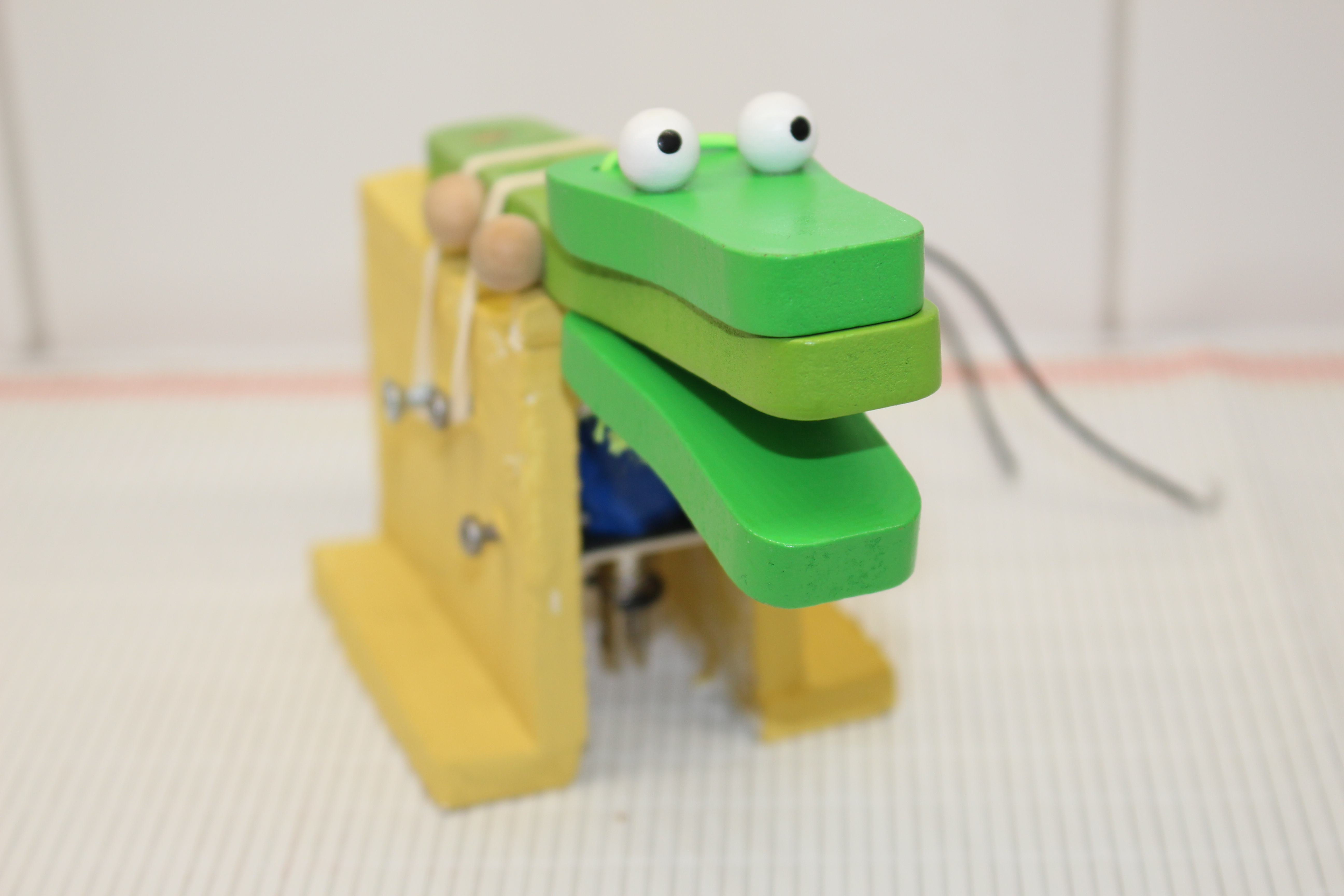
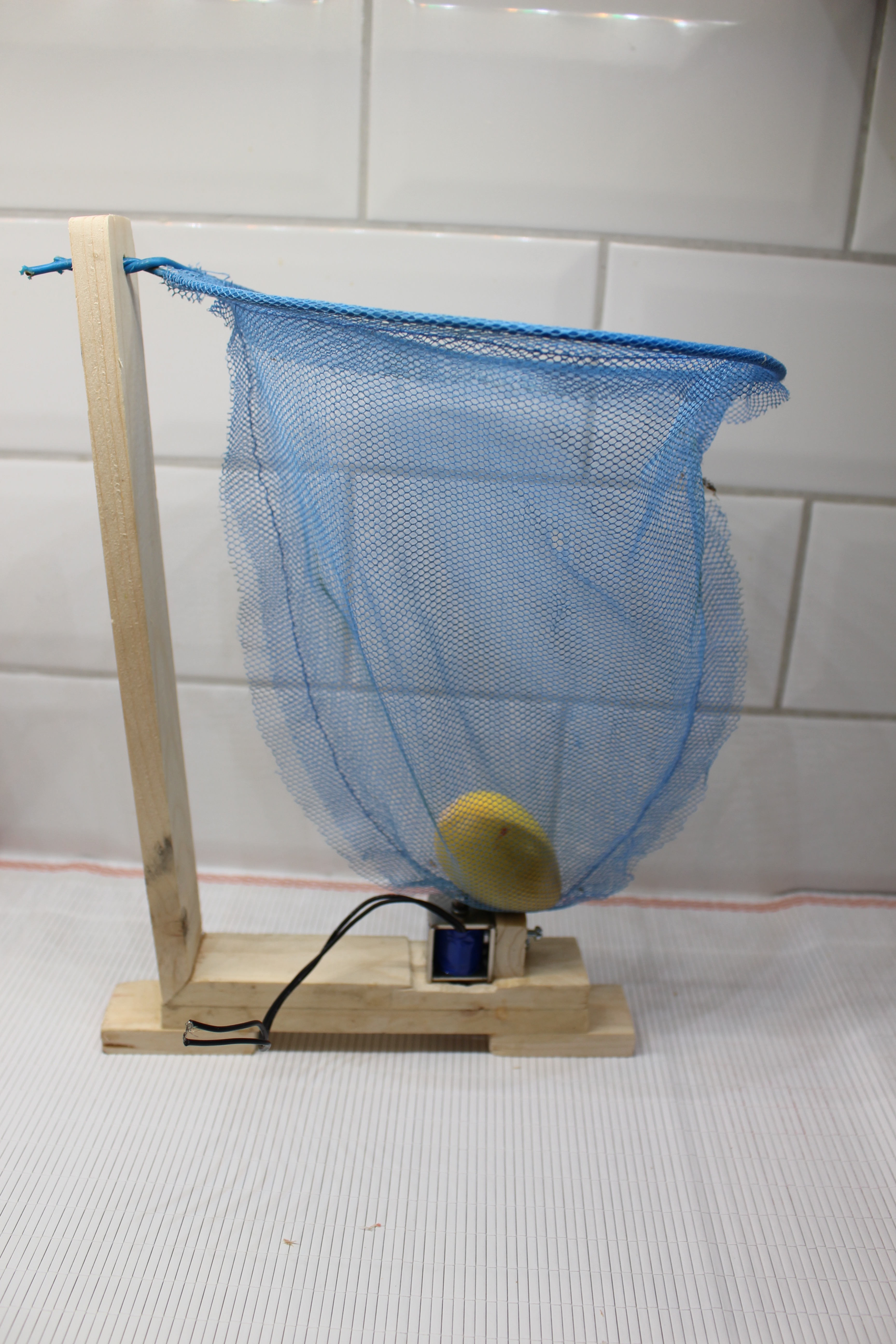
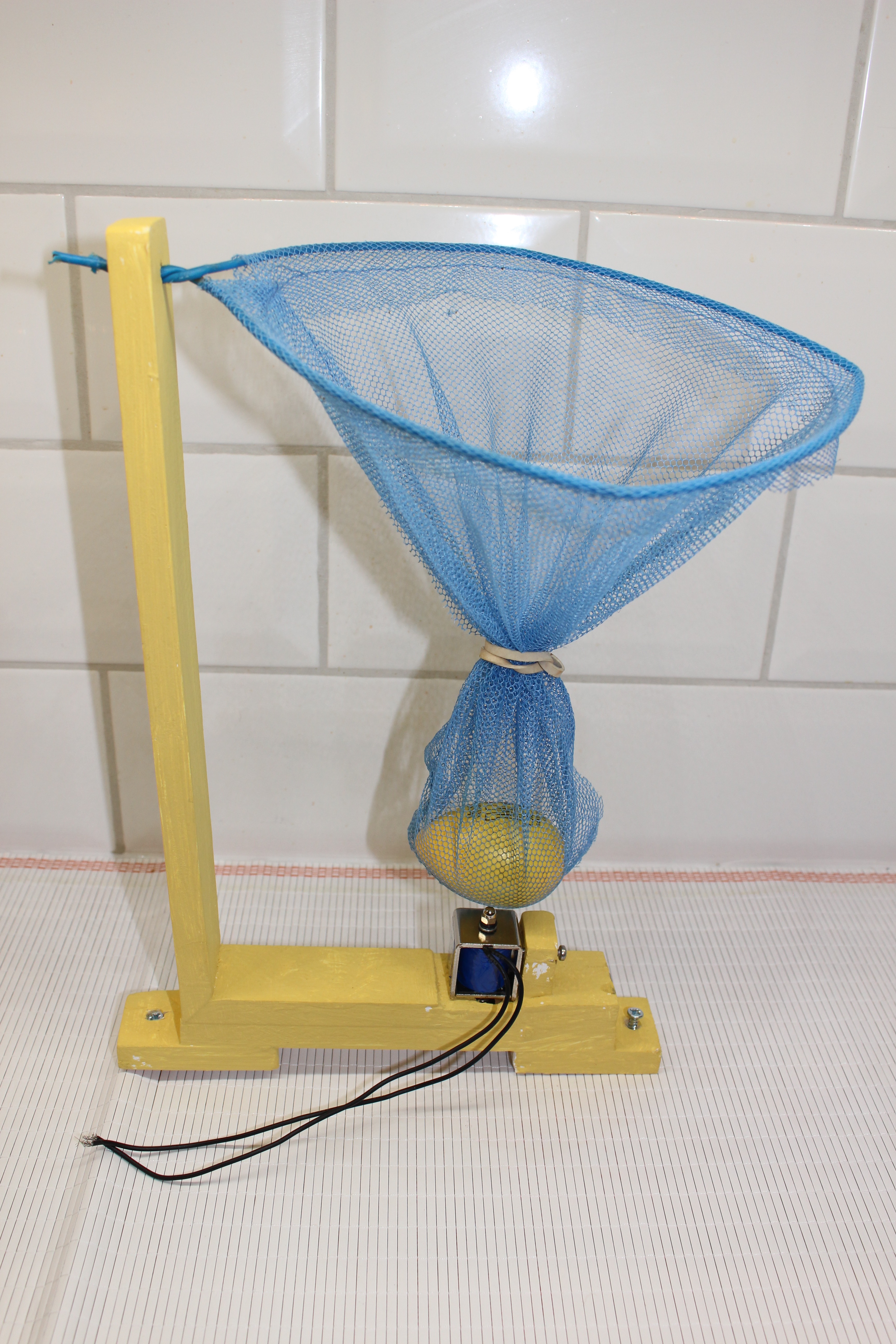
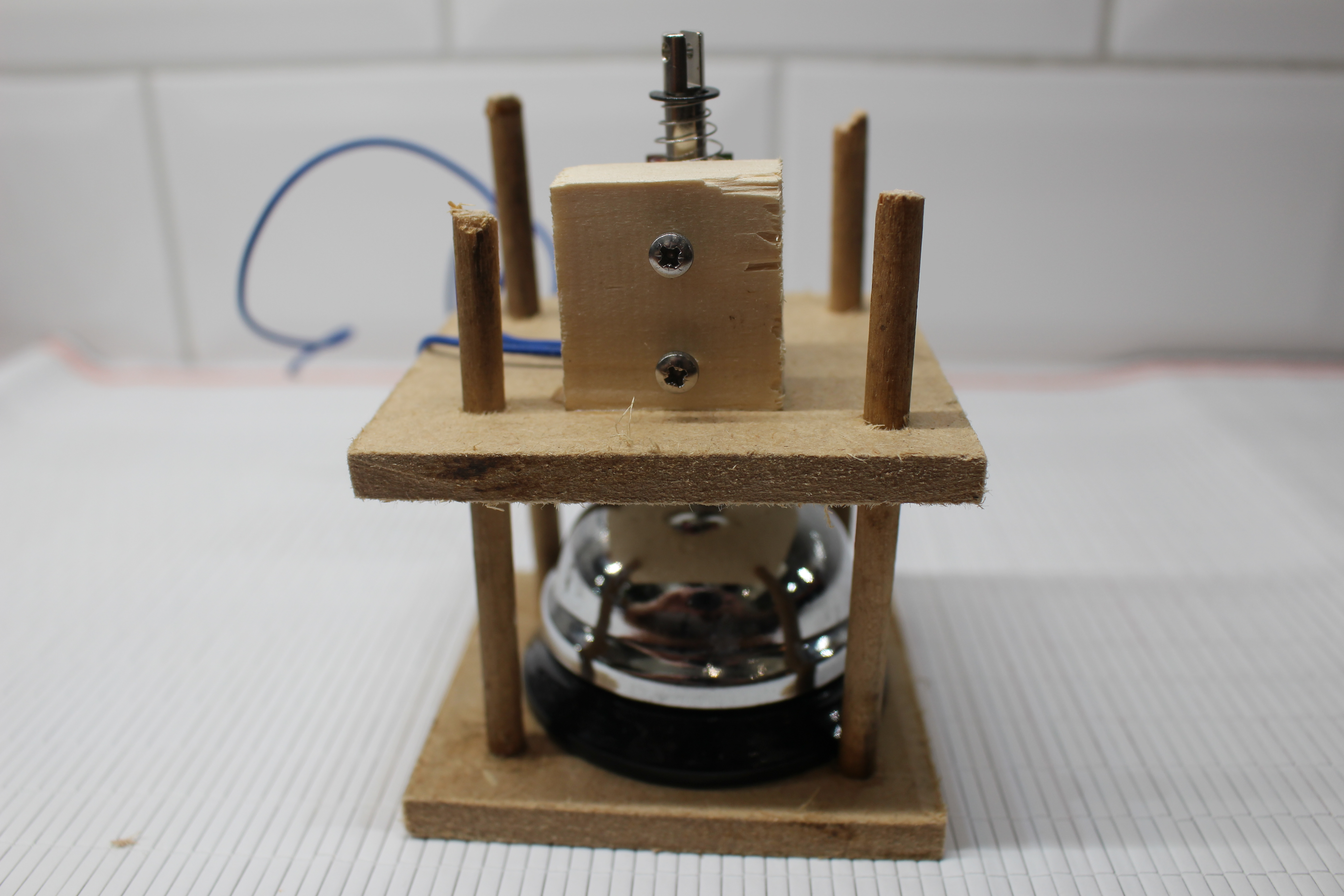
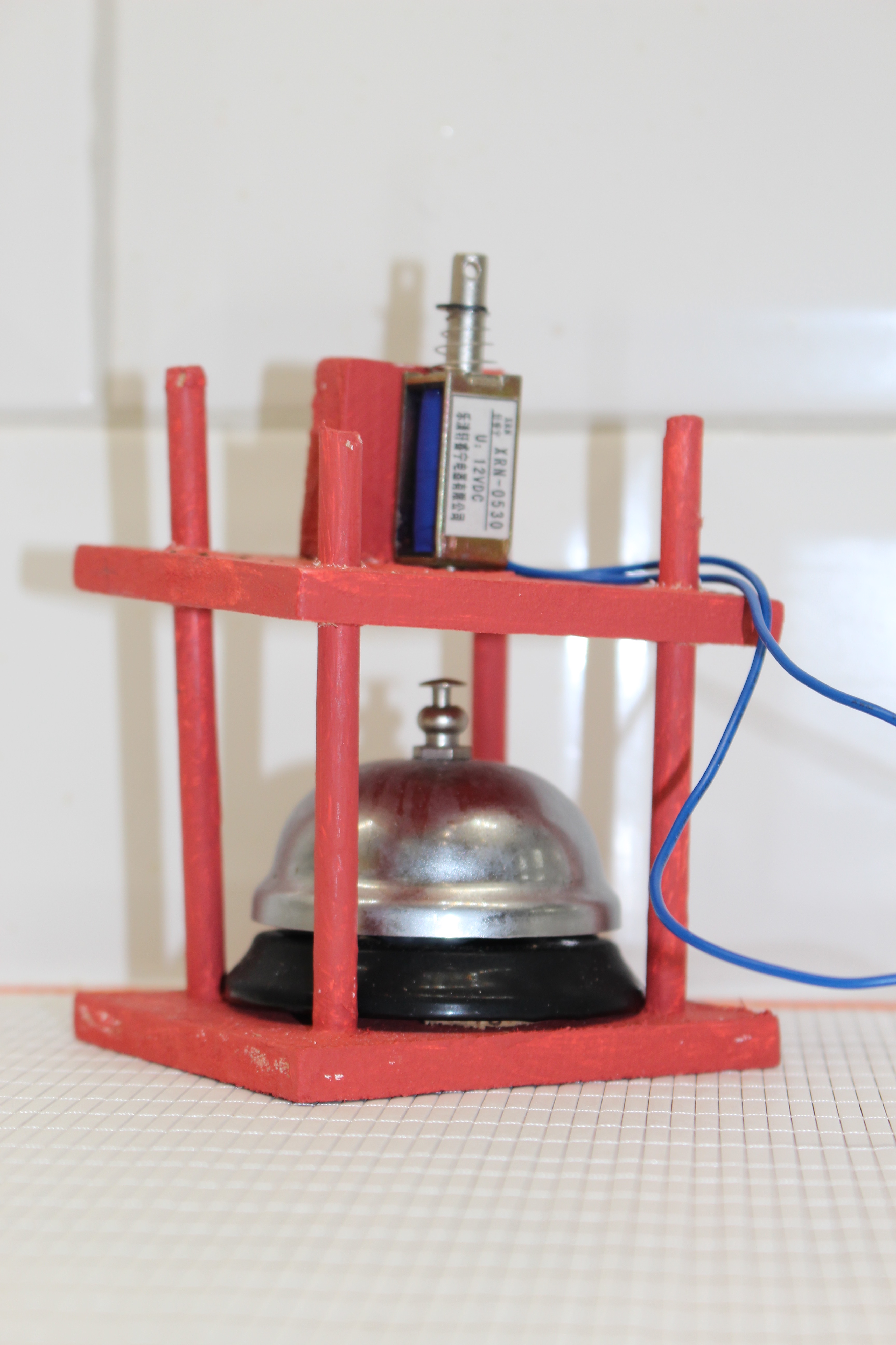
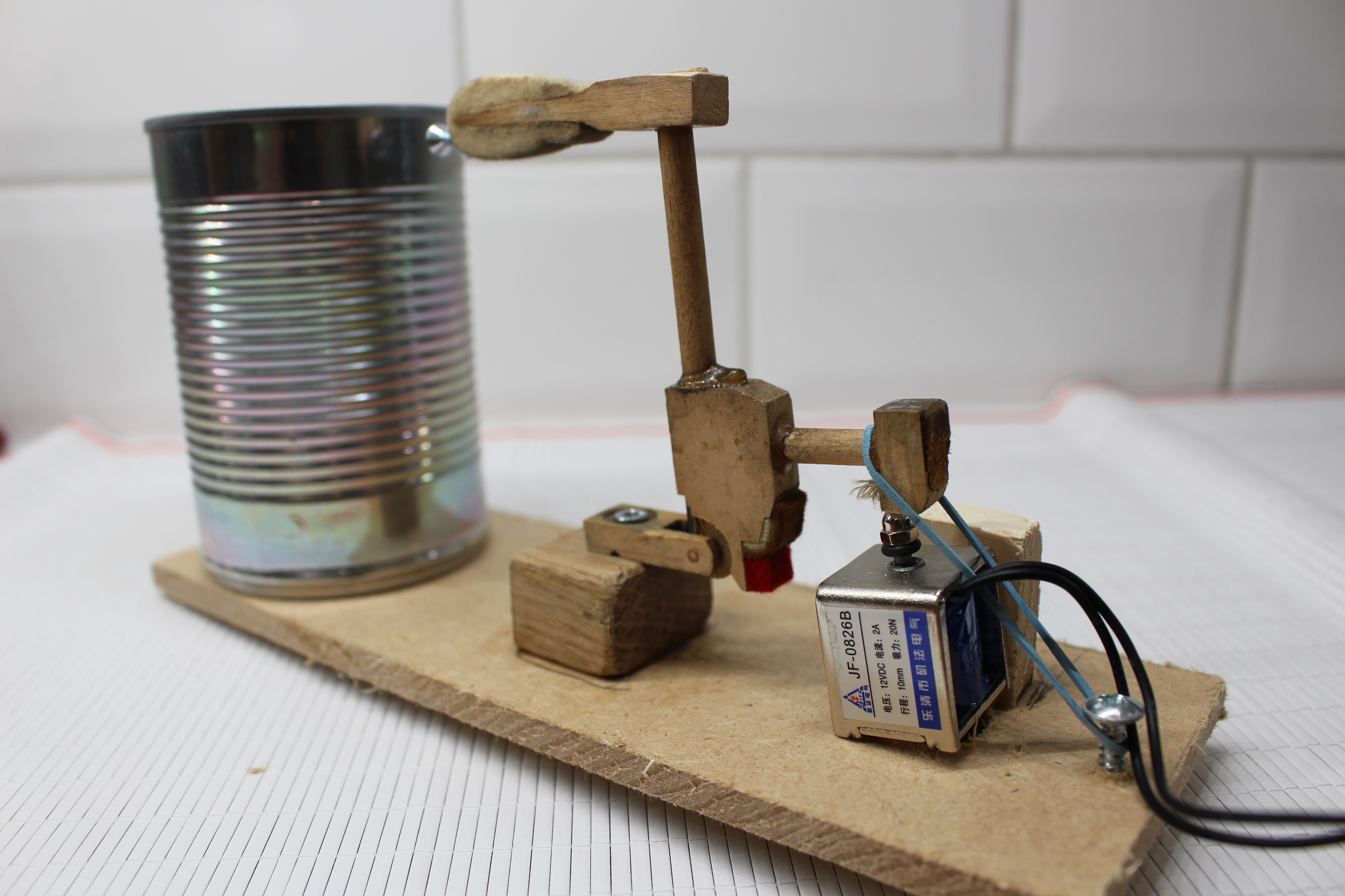
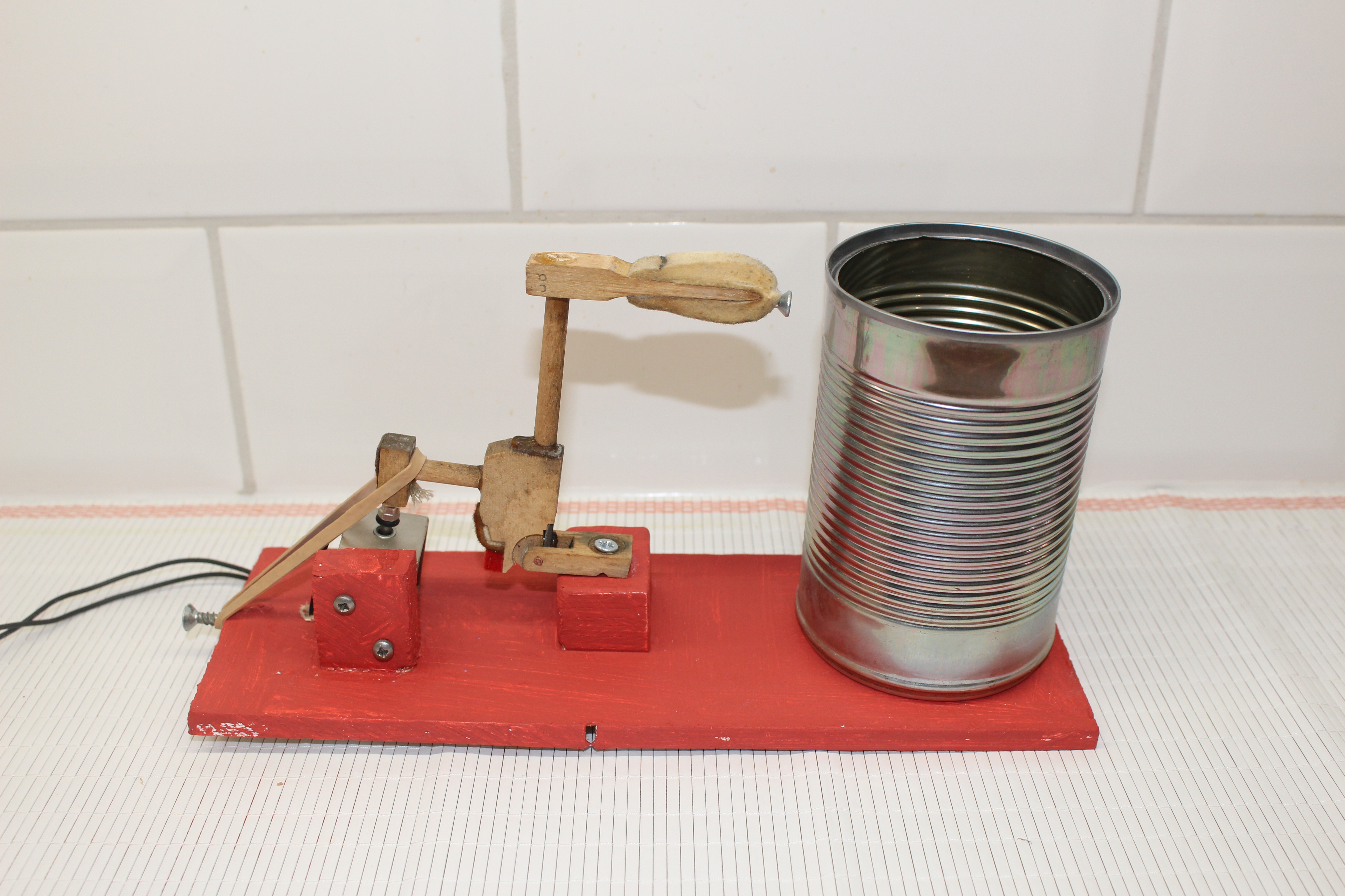
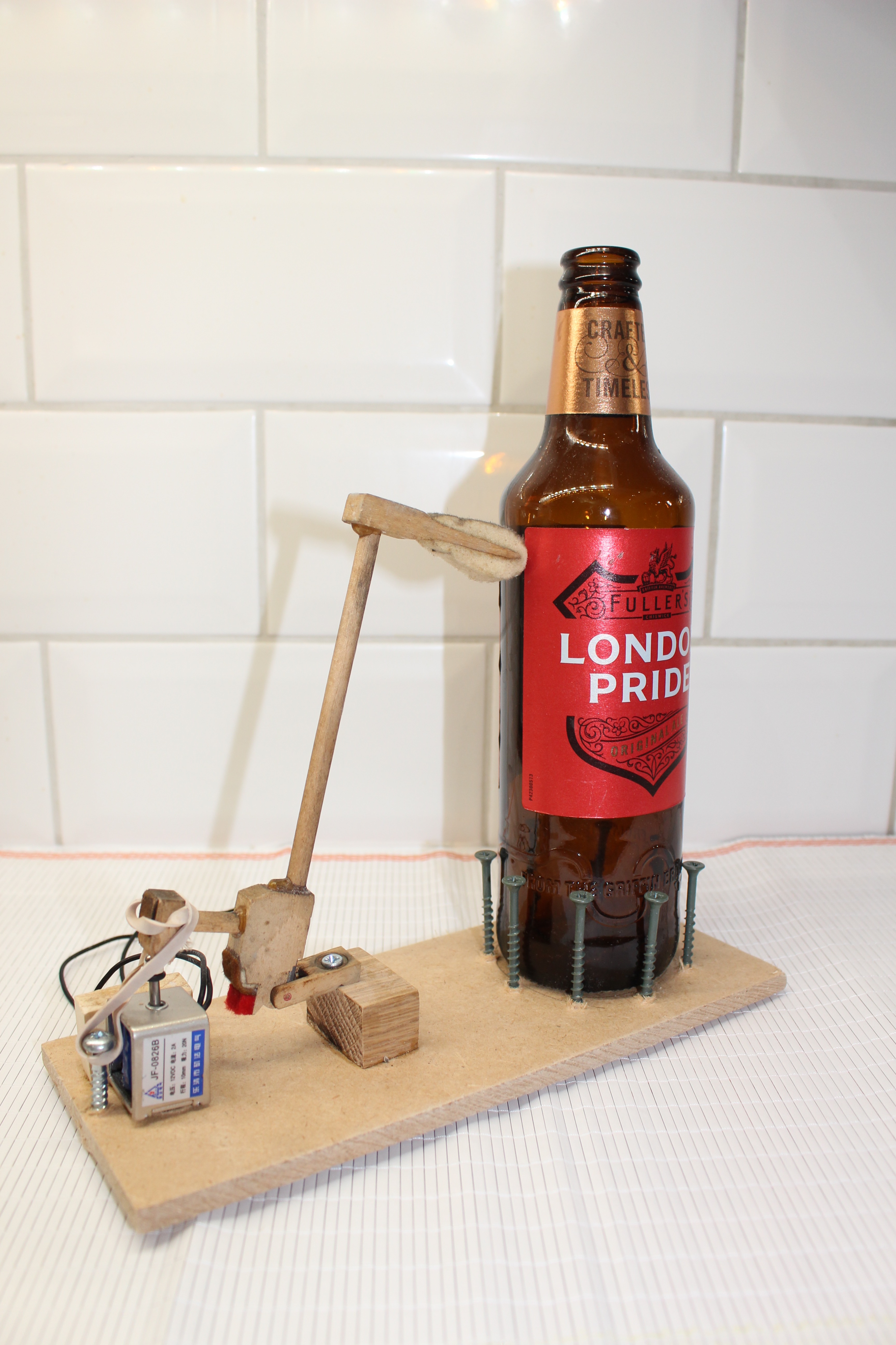
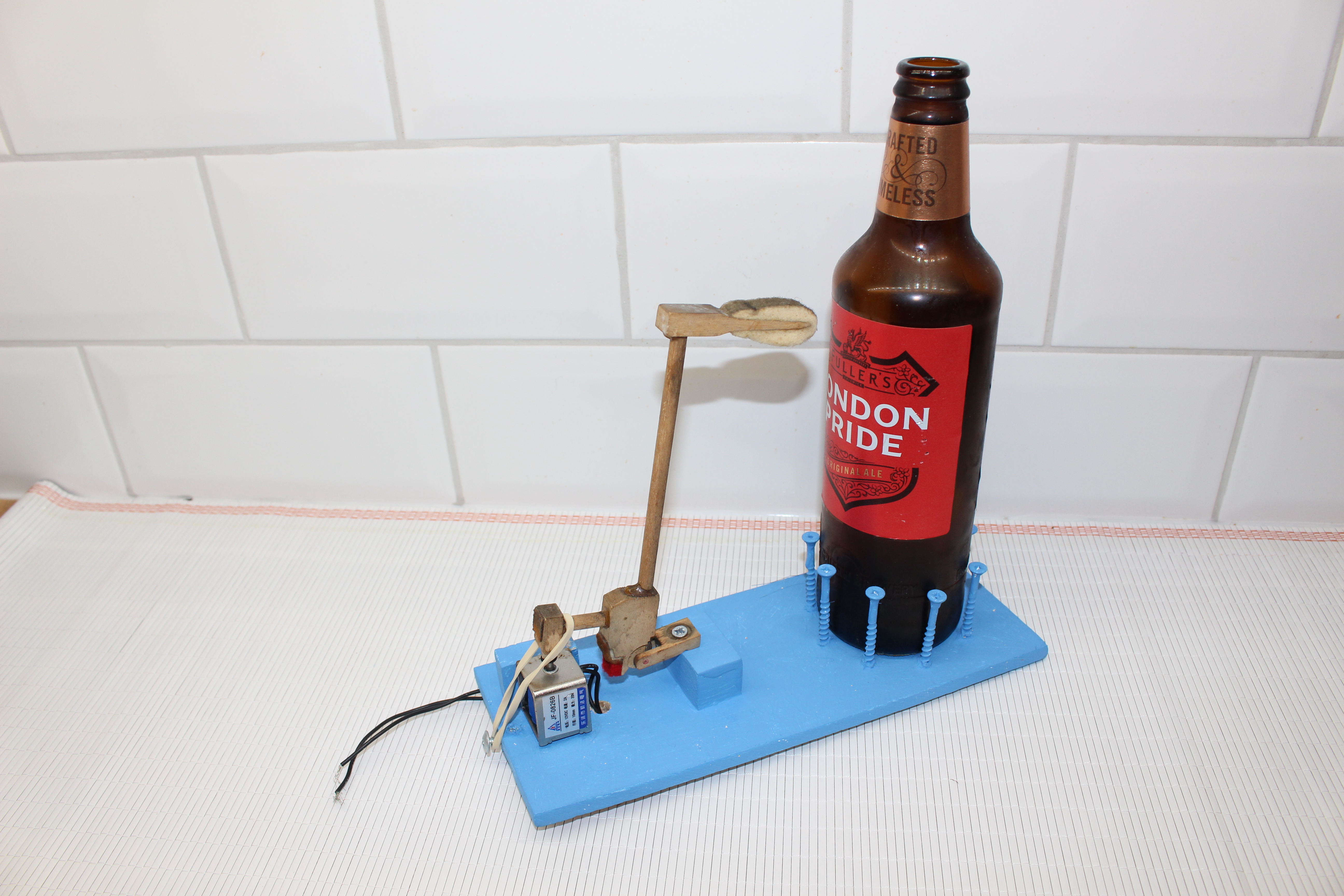
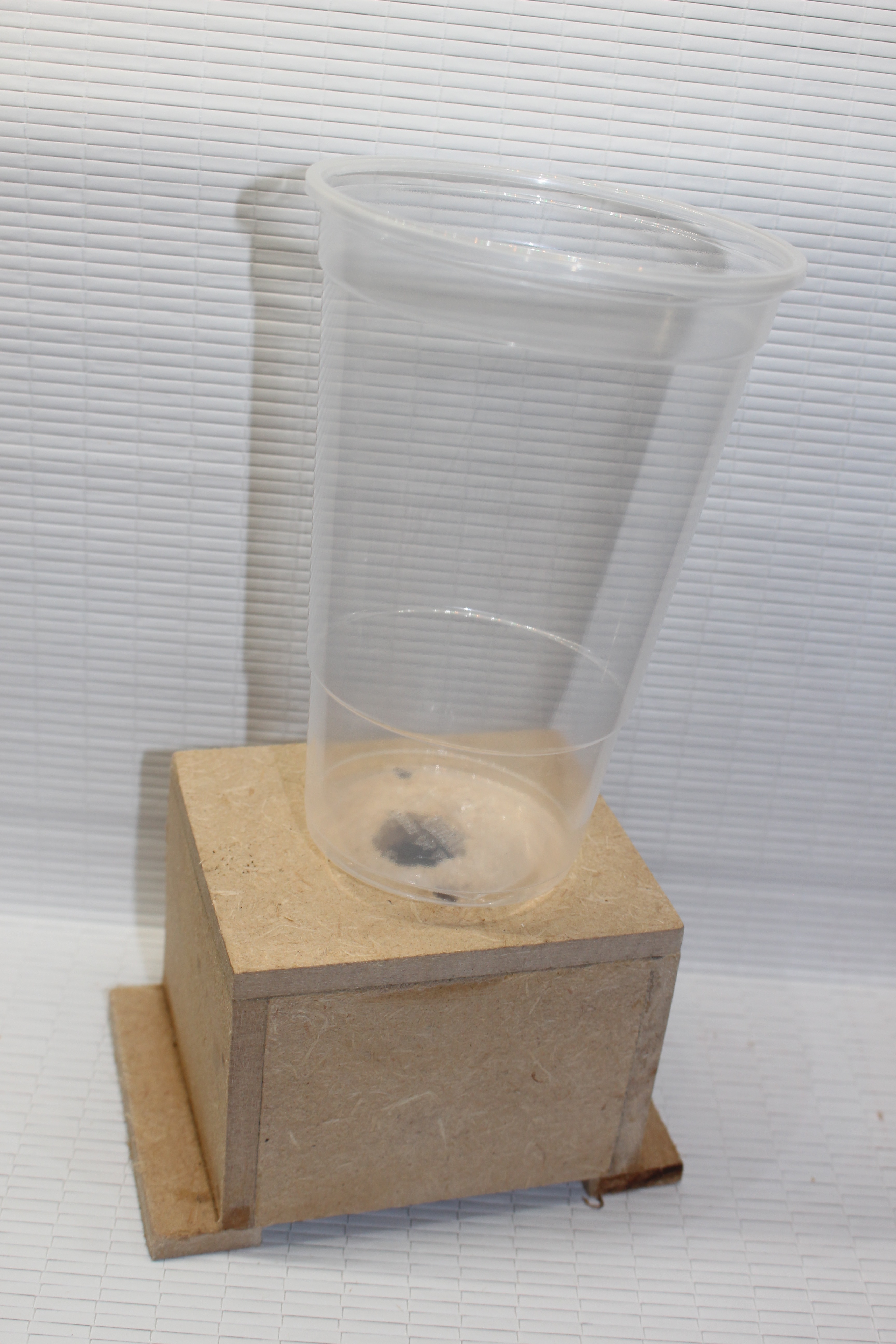
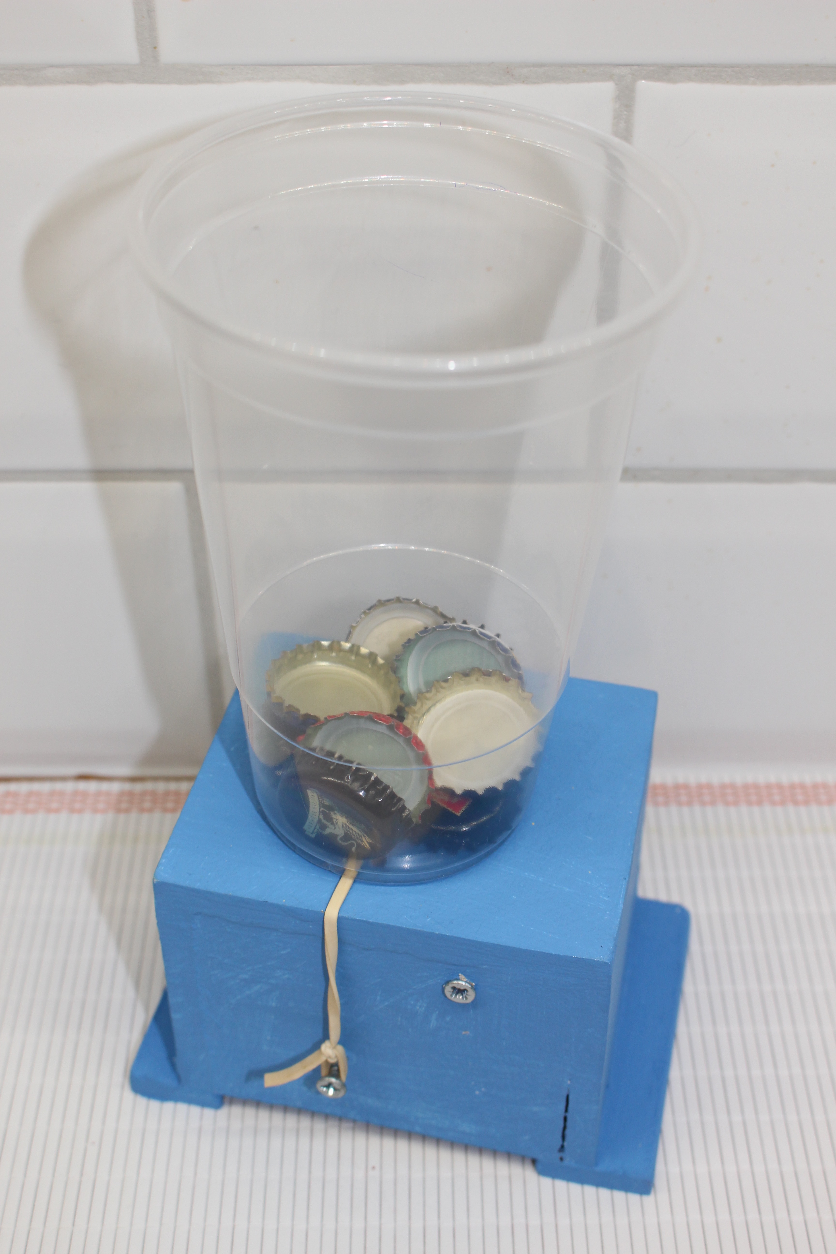
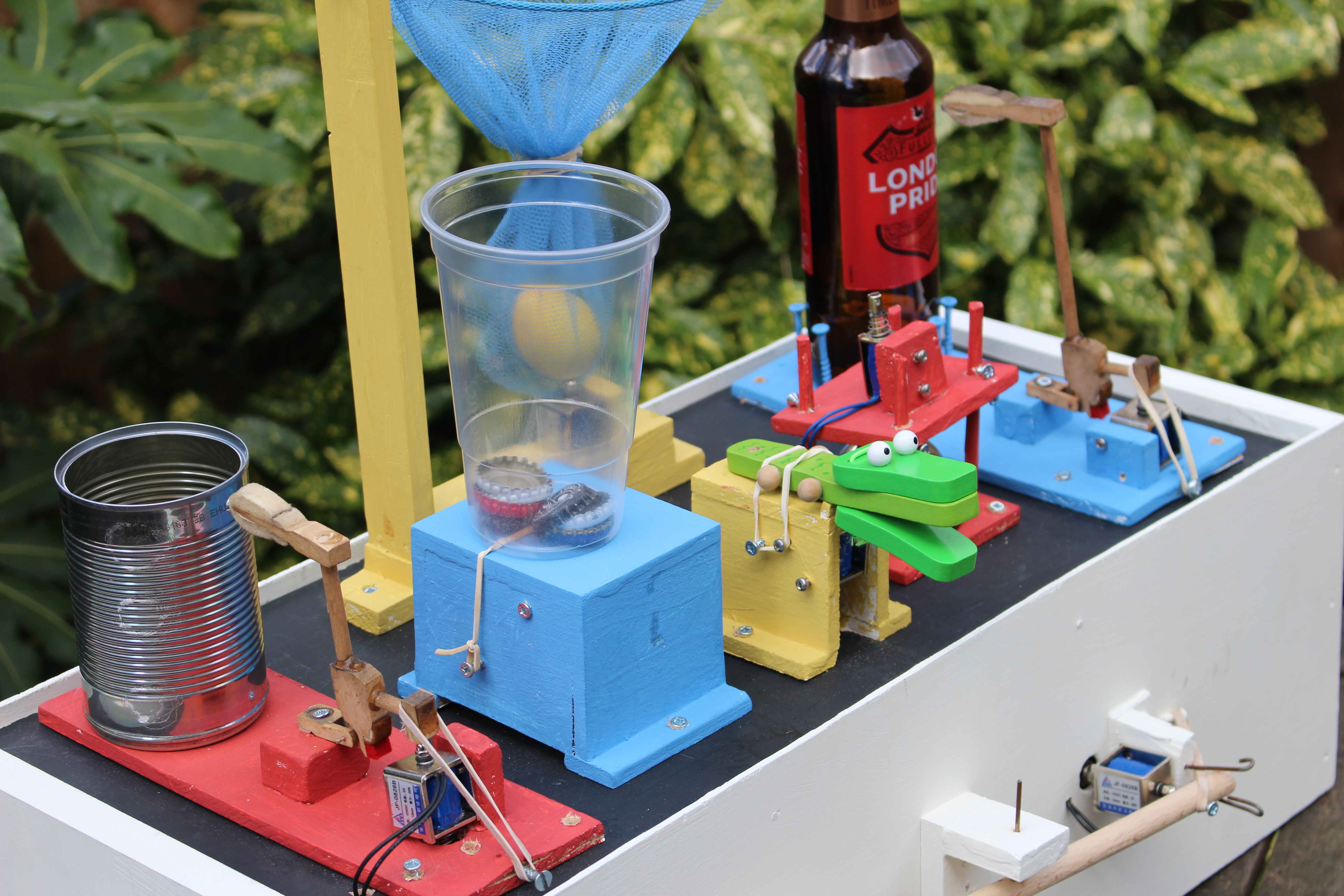
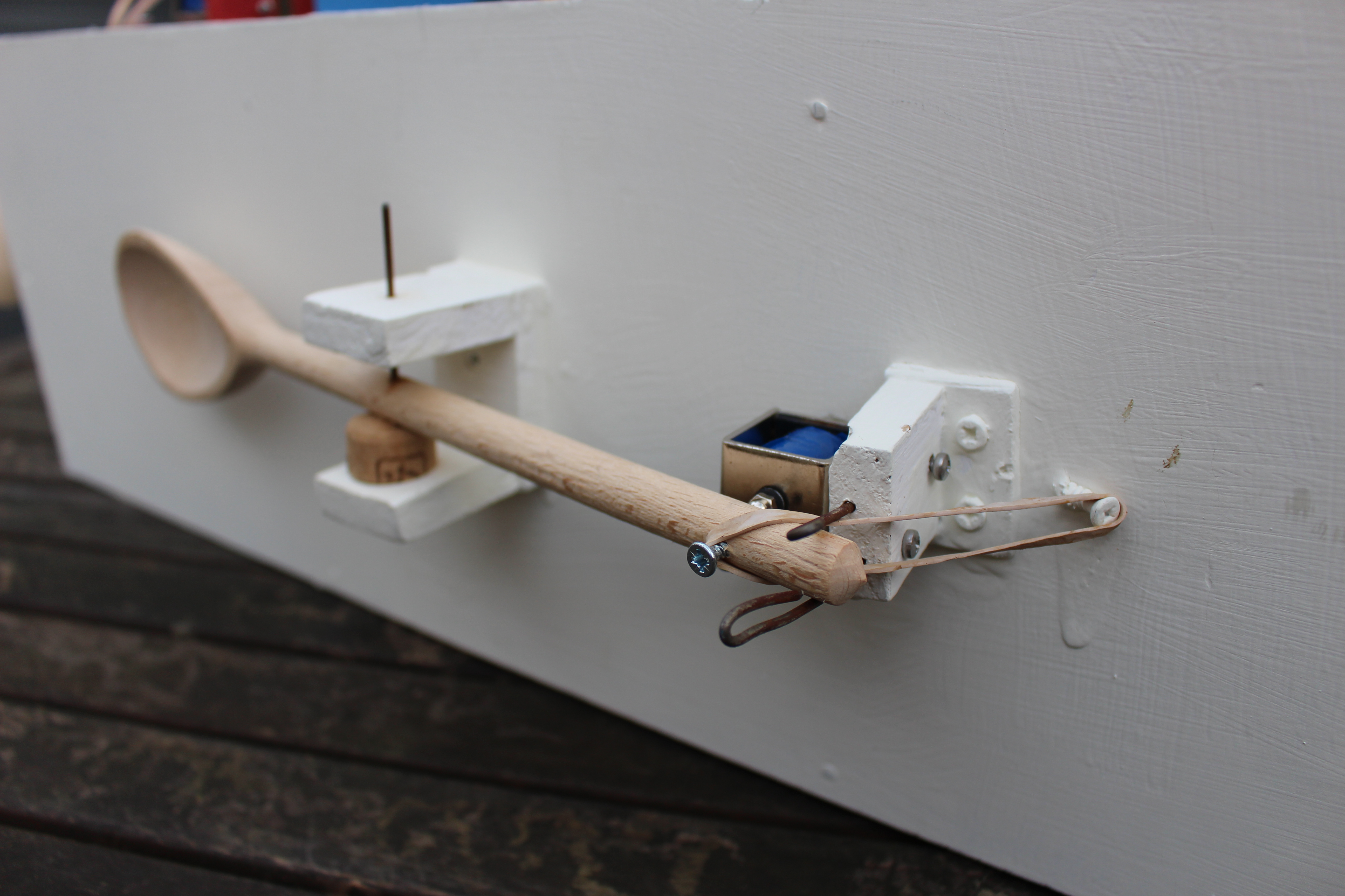
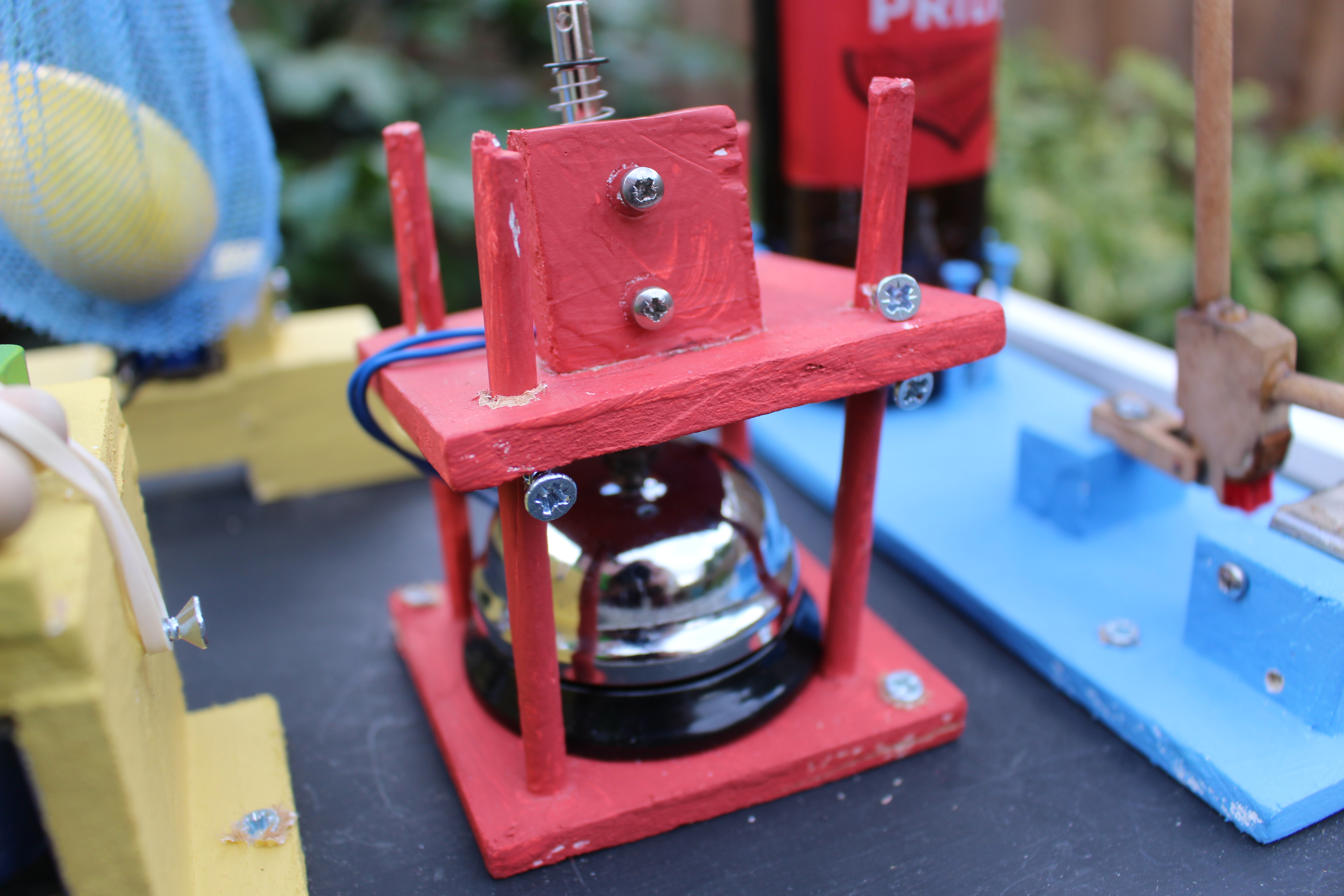
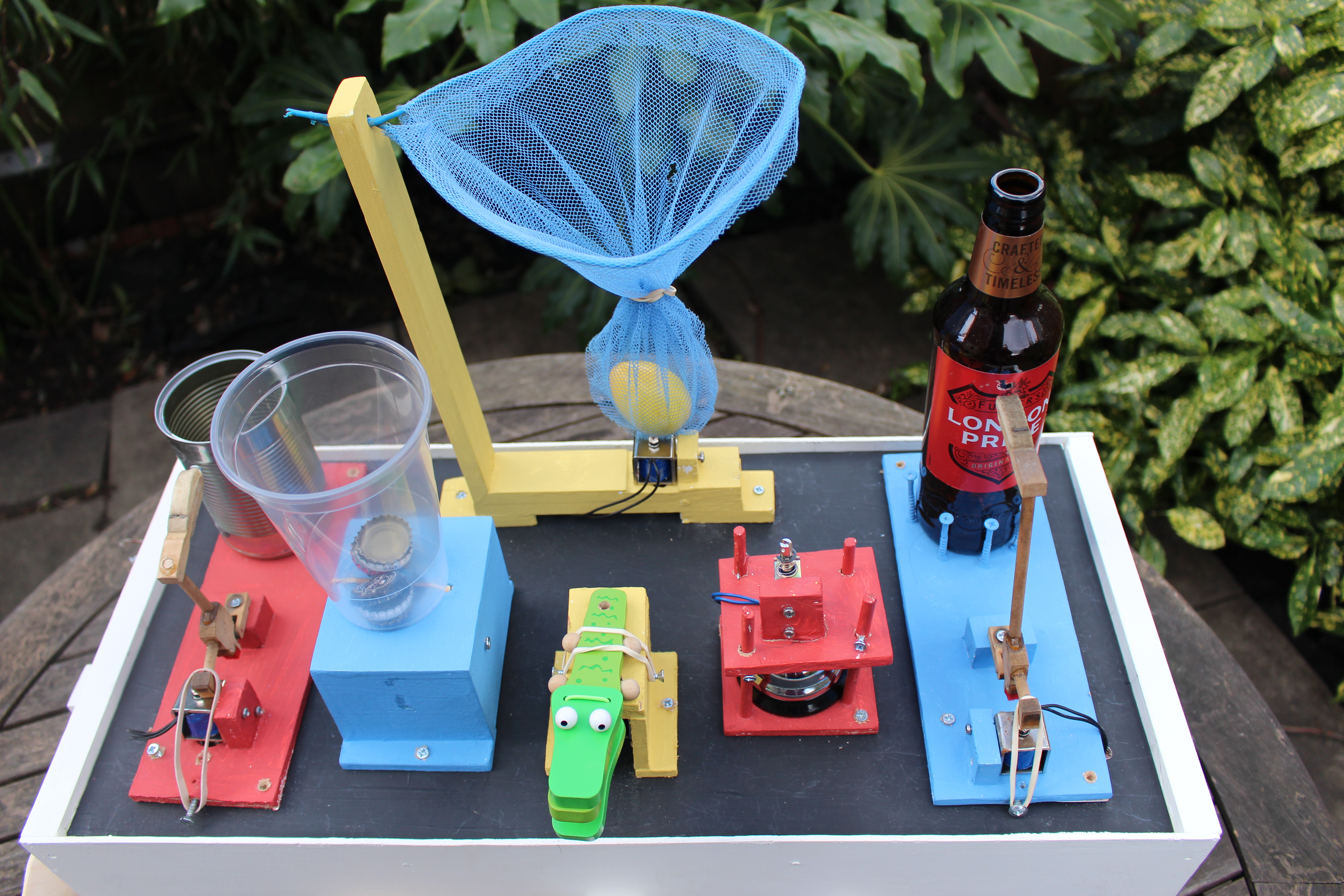
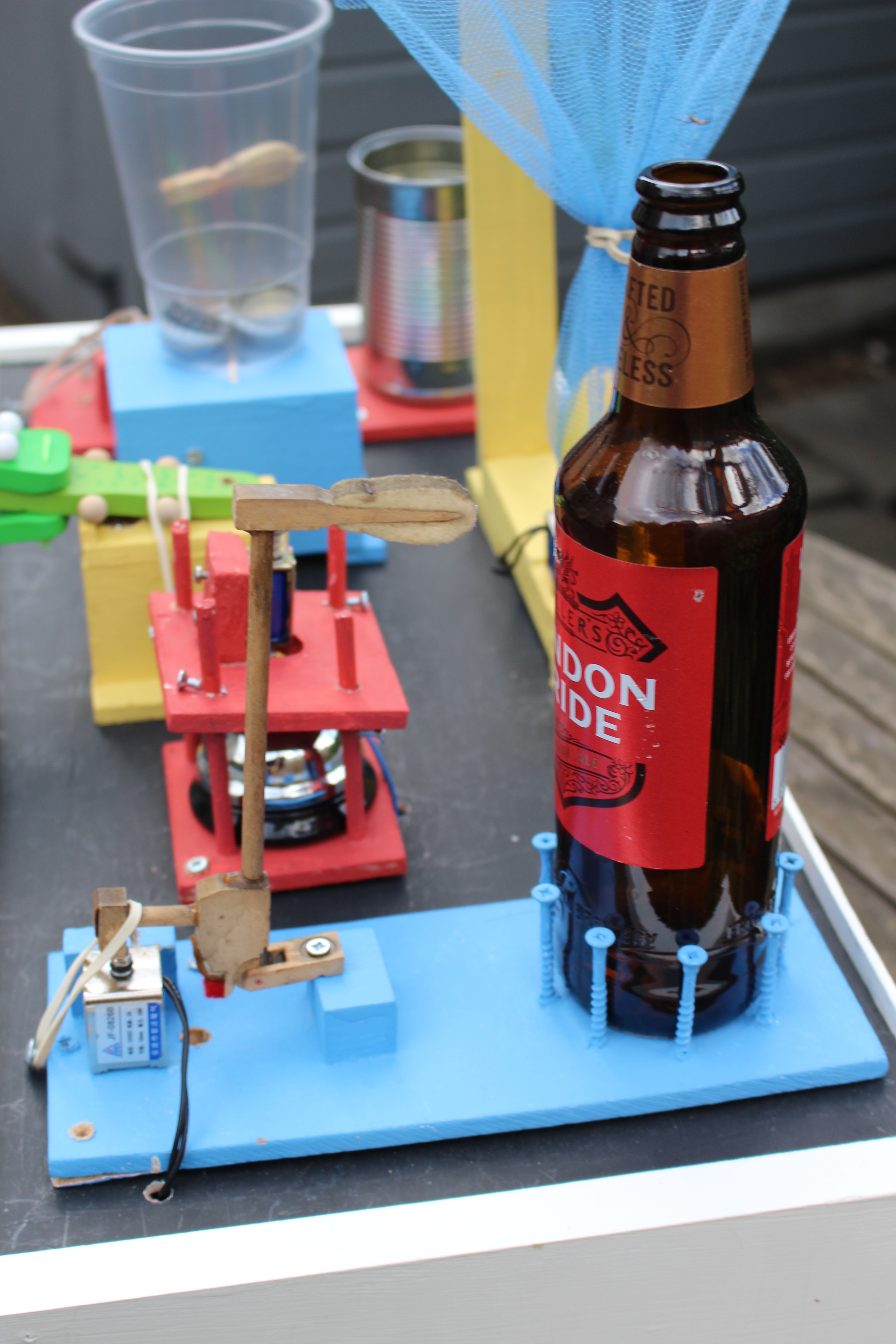
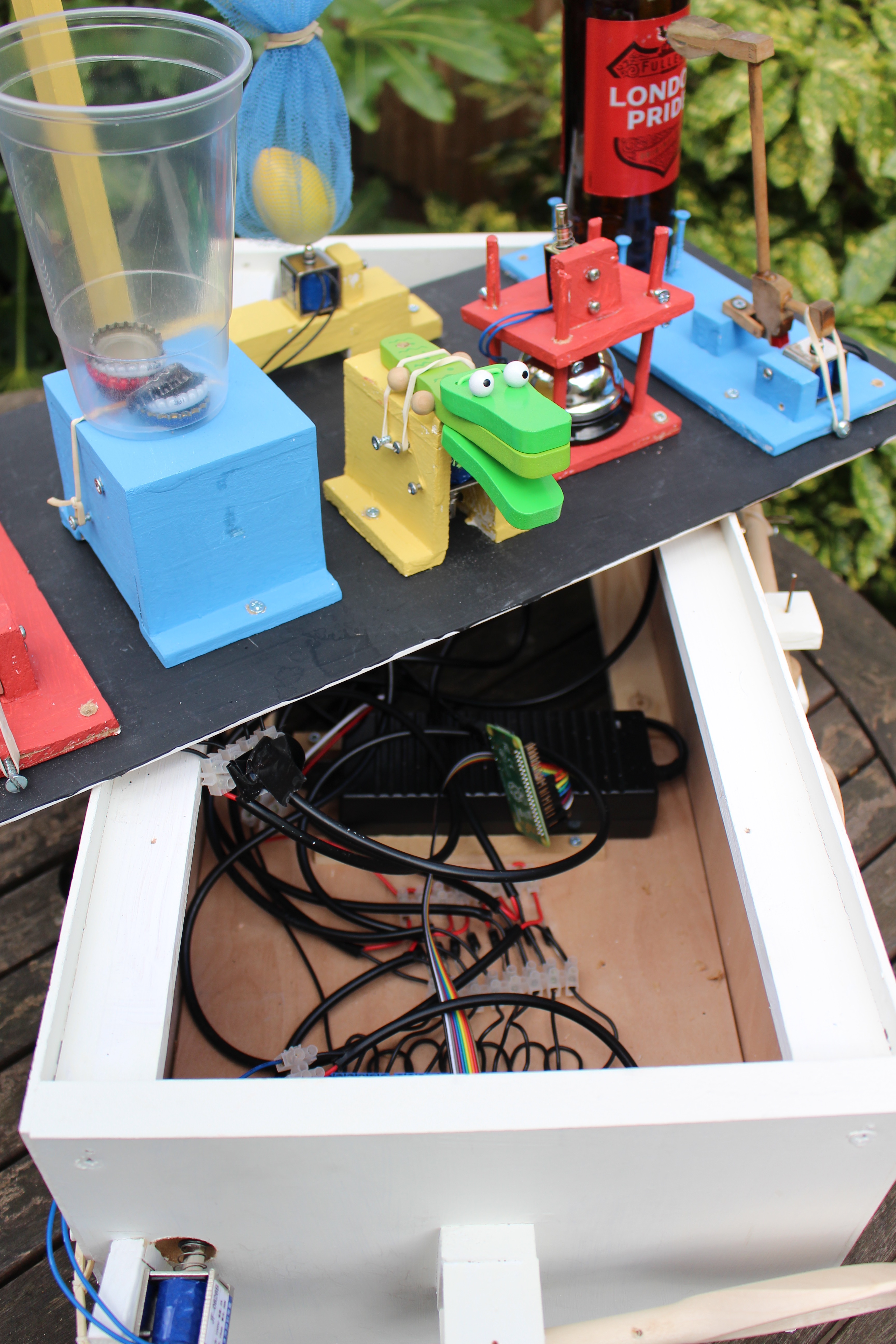
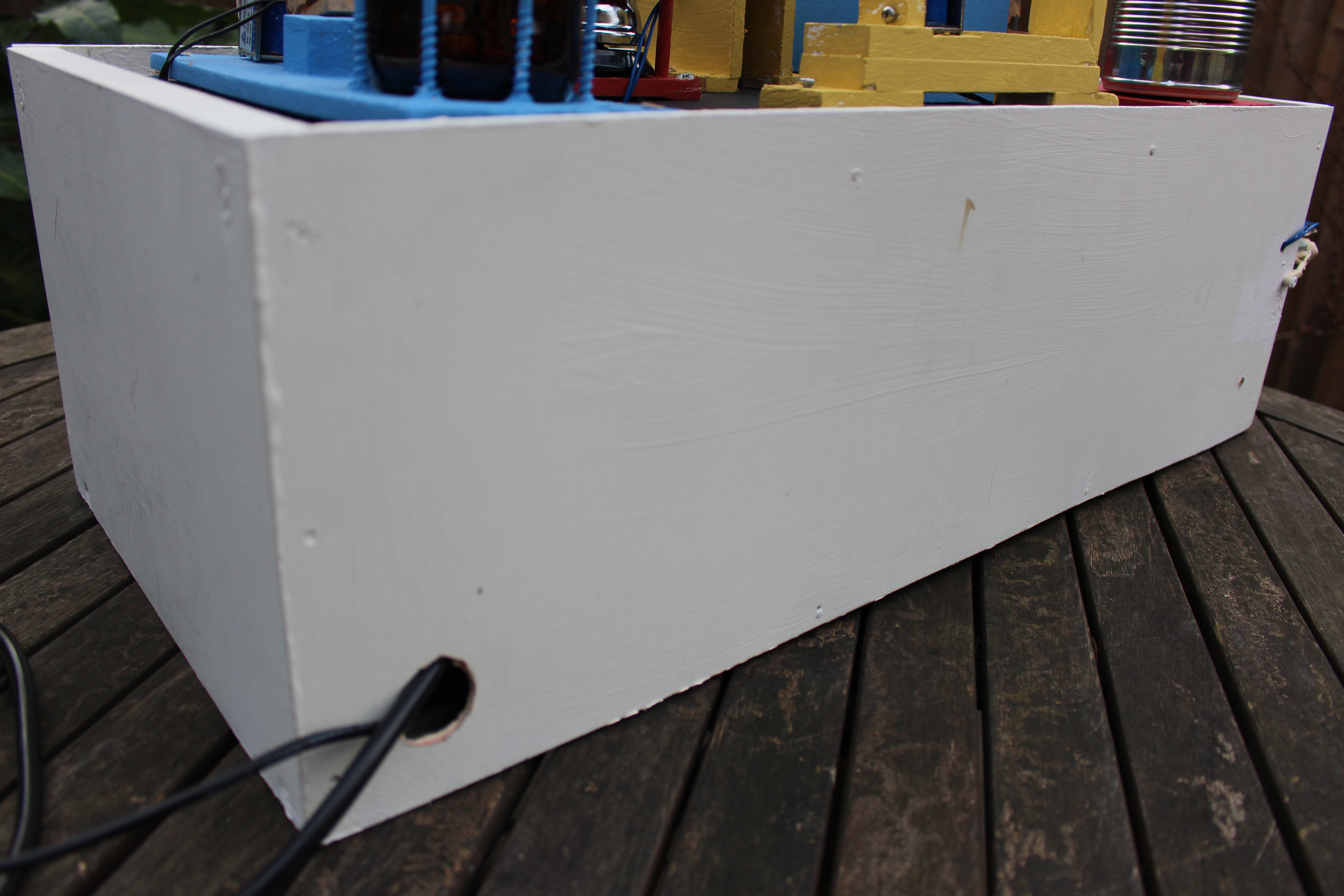
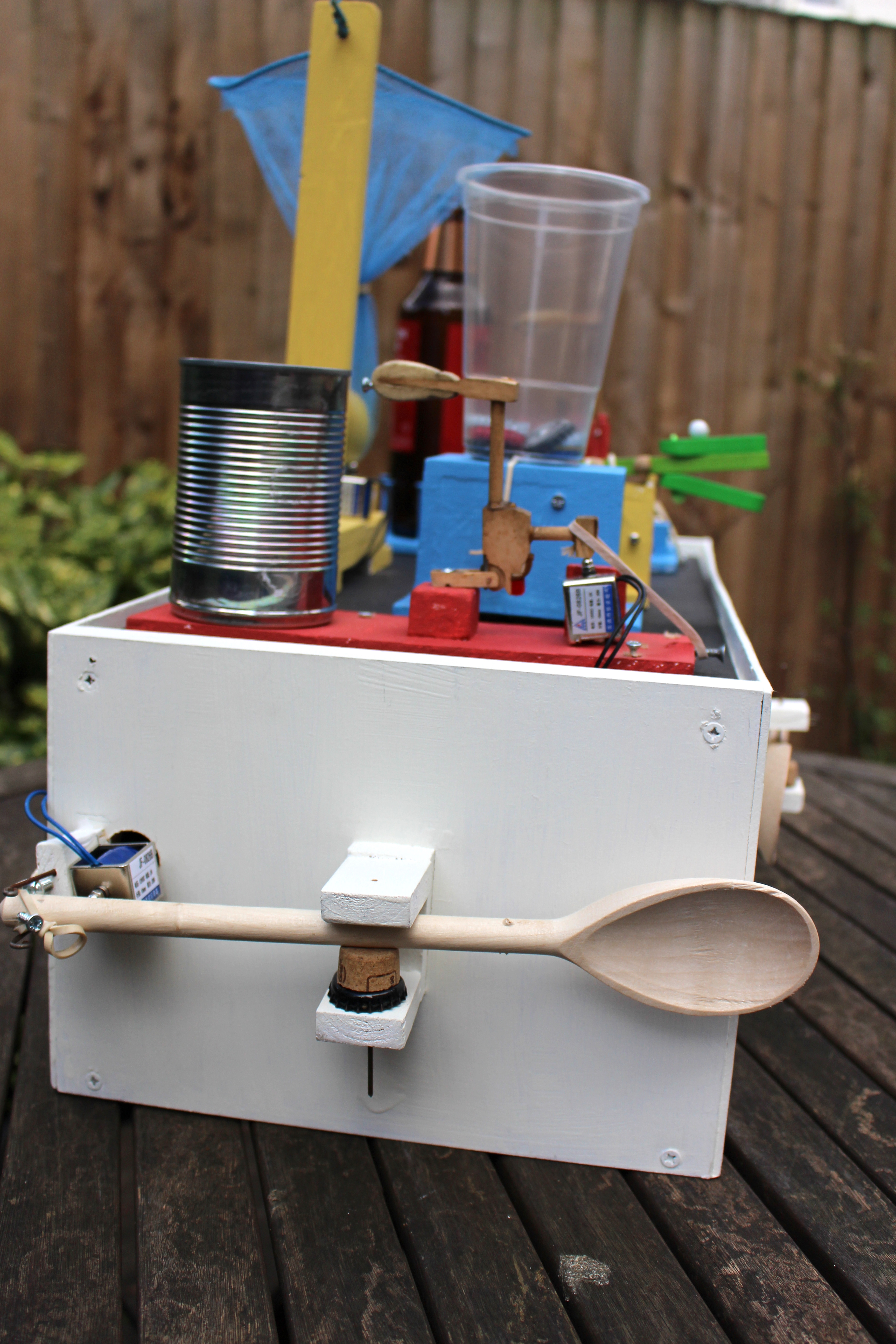
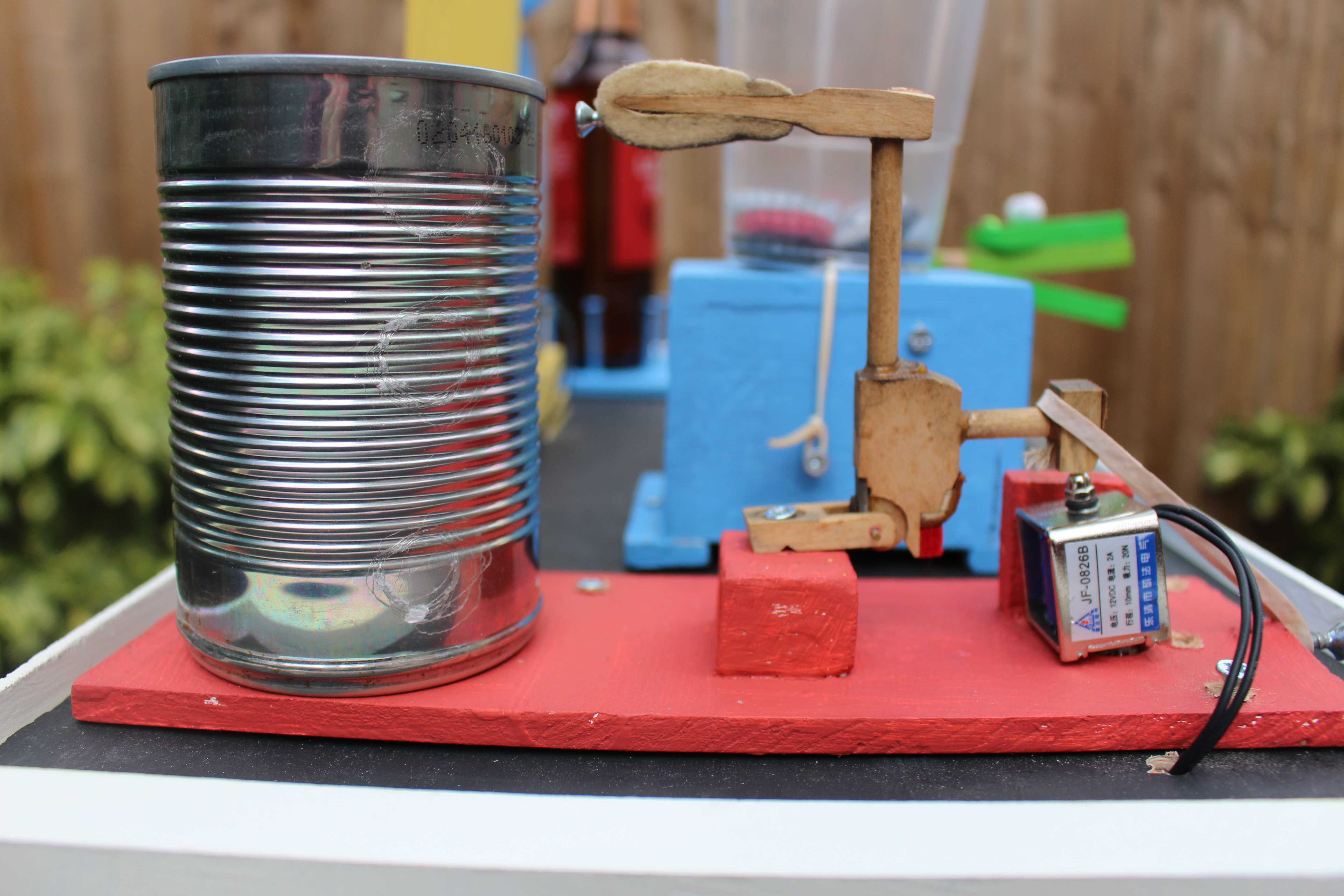
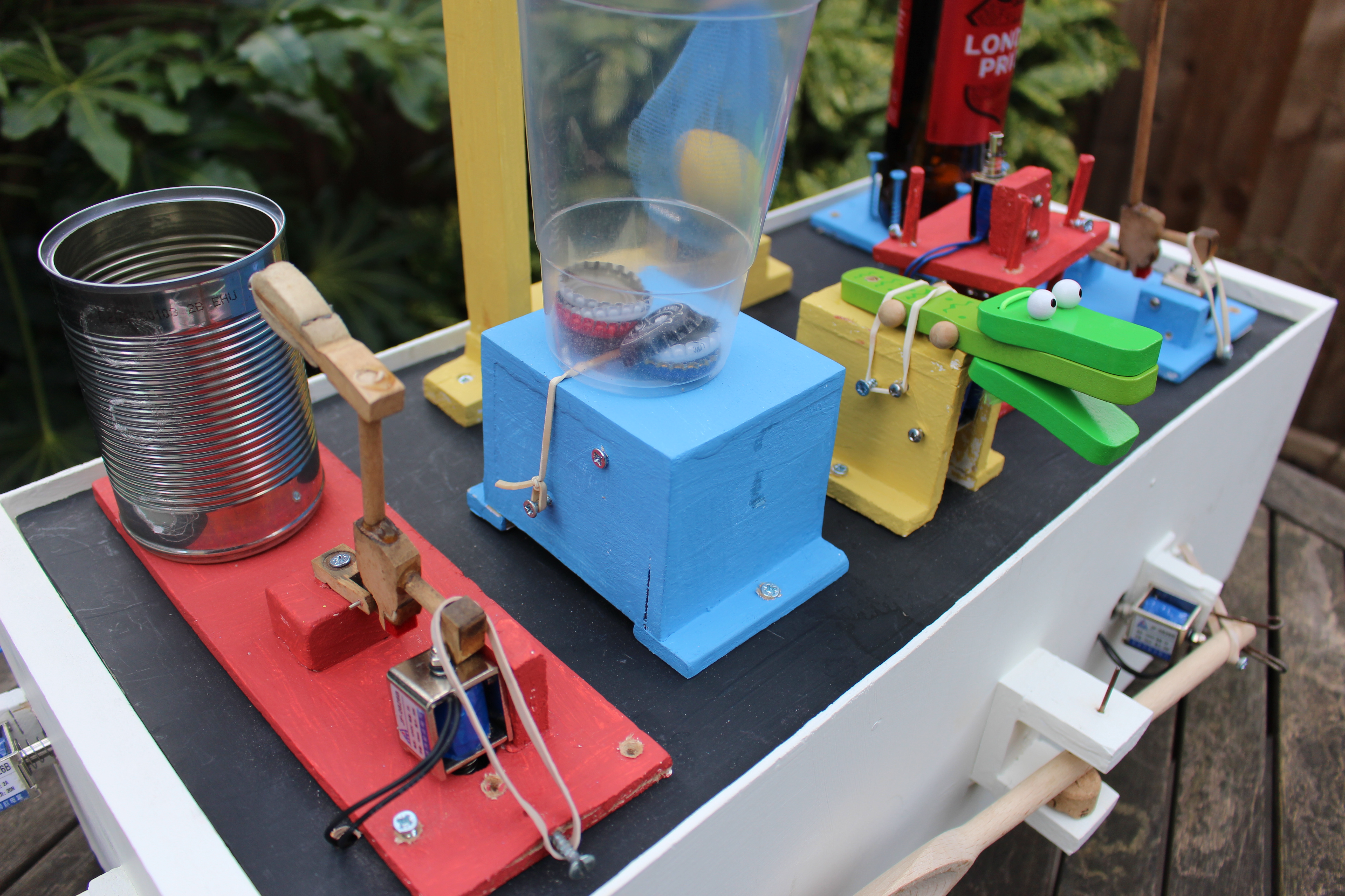
This is where you get to turn your pile of electronic spaghetti into a real drum machine. As said before, what you do here is up to you. Just about anything which makes a noise when hit can be used, and is where you can really transform your project into something unique to you.
I had a good rummage around my home for ideas for the drums which provided the beer bottle, can, shaker, bottle tops and spoons. The fishing net was found on the beach, and the desk bell and crocodile castanet came from eBay. I found a broken up piano in a skip, this provided the hammers for the bottle and can, along with wooden dowling to hold the bell in place and metal rods to pivot and hold the spoons in place.
I made each drum a standalone component, so if one breaks or I am not happy with it, I can switch it out with another without too much fuss.
The solenoids come with bolt holes requiring M3 bolts. Drilling the holes into the wood was a bit tricky as you have to get the positioning just right, but found holding the solenoid in position then marking the holes with a bradawl before drilling worked well.
I mostly used 6mm MDF (offcuts from my local DIY shop) for the drums along a few bits of scrap wood, held together with either glue or screws.
The hammers on the can and beer bottle are probably unnecessary, as you could get just a good hit straight from the solenoid, but I wanted to get as much movement in the machine as possible to make it visually interesting.
Housing
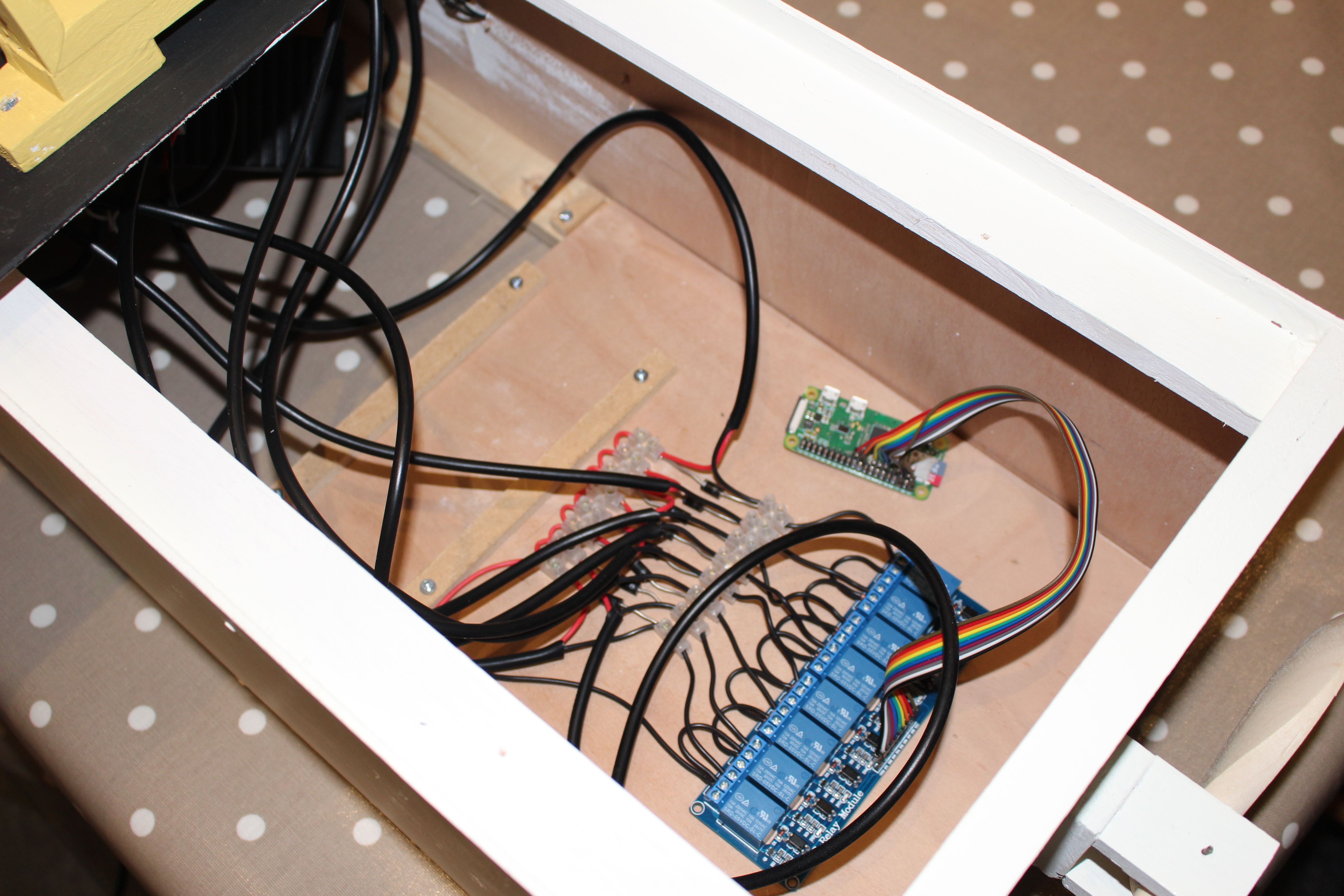
The housing is a simple rough and ready box made from 3.6mm plywood, 18mm MDF and some stripwood. I wanted thin plywood for the front of the box so it would resonate when hit with a spoon, but the wood choices were mainly driven by what I already had in the shed and the scrap wood section in my local DIY shop. I made a platform at the bottom of the box to keep the electronics, and another platform to hold the drums. To make the box:
1. Cut 2 equal sizes of MDF to make the ends
2. Cut 4 pieces of stripwood (I used 34mm x 12mm) 50mm shorter than the desired width of the box
3. Nail the stripwood to the 2 MDF ends to form the box shape. Put the stripwood about 1 cm away from the top and the bottom of the box.
4. Cut 2 pieces of plywood to match the width and height of the box. Attach these to the front and back of the box by nailing to the mdf and stripwood.
5. Cut a pice of plywood to fit inside the box and place on the bottom pieces of stripwood to hold the electronics. I made mine about half the length of the box.
6. Cut another piece of plywood to attach the drums to. This sits on the top pieces of stripwood.
7. Cut a hole near the bottom platform to feed the power cables through.
Painting
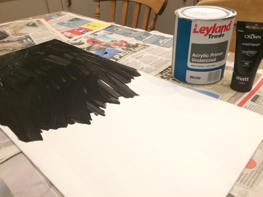
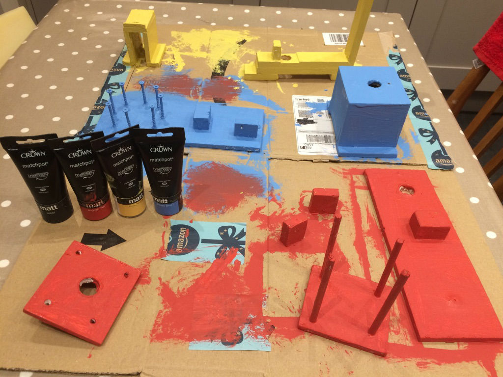
To paint, I used Acrylic Primer Undercoat followed by Crown Matt tester pots. The tester pots are a good way to get a variety of colours at a cheap price.
Sit Back and Have Fun!
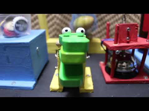
And there you have it, a pretty cool drum machine. The gist for the sequence in youtube video can be found here.
If you go ahead and make your own please share, I would love to see what you come up with. Have fun!