500W DIY Multiport USB-PD Fast Charger
1466 Views, 7 Favorites, 0 Comments
500W DIY Multiport USB-PD Fast Charger

Version 2.0 of my fast charger, now with 4 USB-C ports [100 watt per port] and 8 USB-A ports + improved cooling and safety features. The total cost of materials was around $69 USD, which makes it way cheaper than anything available in the market [as of 2025].
This charger supports USB PD 3.0 (100W), PPS (100W), SuperVOOC (80W), and QC 4.0 (100W) per port. The working temperature for the fan can be set and changed, and the temperature is displayed on a 7-segment display.
This uses two fans for redundancy that run in a push-pull configuration. This seems overkill, but I added these and other safety measures because this will work more as a power supply and not as a charger. Most high-powered USB-C chargers that go above 100 watts heat up a lot and shut down due to thermal issues. I do not want this to happen, since I will be constantly powering two laptops from it.
Version 1 of the fast charger has been running for a year from the date of publishing this instructable, and the current version has been in use for the past four months without any issues, so this is a very stable build. All components used here are off-the-shelf parts, and the 3D-printed cases are optional – you can use simple brass standoffs if you want. I will provide reasoning and alternatives to products wherever possible, but please read the datasheet of each component.
Supplies
.jpg)
.jpg)

.jpg)

Electronic components:
- SW3518s USB PD buck converter (4 port)
- XFW KC 42-4 QC 3.0 buck converter (4 port)
- XH W1209 temperature ctrl module with NTC sensor
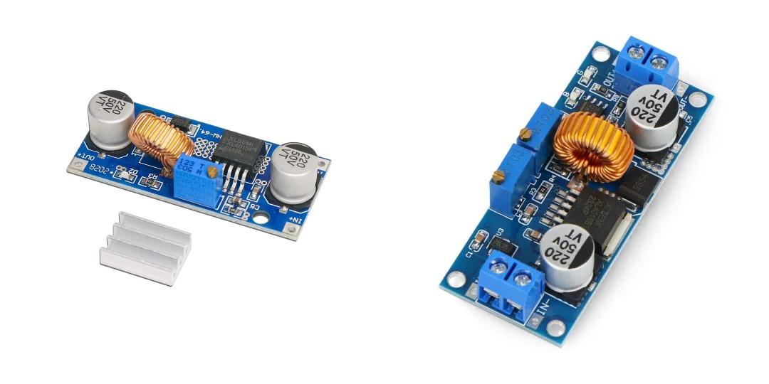
- XL 4015/4005 buck convertor (any module will wrk)
- 12V fan
- two 20 A diodes
- 24 V - 500 W (or higher) power supply with a fan
Electrical Components:
- IEC male and female connector (with inbuilt switch and fuse)
- 16 AWG silicone wire (or 14AWG) black and red color
- 22 AWG wire (small length) red, black and green
- 3 core wire with electric plug
- two 5A fuses
- crimp connectors(fork and pin/ferrule)
- heatsink for diodes and XL4015 (x4)
Tools and supplies:
- acrylic case for W1209
- 3d printed case for SW3518S
- 3d printed case for XFW KC42-4
- sunboard, acrylic, mdf or any insulating material to attach all parts to
- a plastic case/shell to house the charger
- extra knife/k-series soldering iron tip for cutting plastic
- Dremel or sander
STL file links are given below, original creators of the files are BotMeka and HansGrau, pls give them a follow!
Prep


Start by checking and ordering the 3D prints. The materials I used here are ABS and TPU. Both work well. TPU is more expensive and was used in the first version for the transparent aesthetic. Both were printed with a 0.2 mm nozzle at 30% infill for ABS and 50% infill for TPU.
The acrylic case for the W1209 and NTC sensor is sold as a bundle on electronics and hobby websites. The W1209 is a temperature-controlled relay module commonly used for poultry egg incubators. I decided to use this for fan control instead of a simple N-channel MOSFET because the MOSFET would keep the fan spinning at all times and generate its own heat. Another advantage of the W1209 is that it also provides a temperature readout. You can use the module without an acrylic case or get 3D prints for it.
Since this is a working prototype, I have stuck to using a plastic box. I might add an acrylic box or 3D print one once I am satisfied with the build. I will be using a knife or K-series soldering iron tip to modify the box and shape it. Since the temperatures will not get very high, you can use almost any material for the box shell.
The XL4015 is used to convert the 24V output from the power supply to 12V for the fan and the W1209 module. Set it to 12V by connecting it to the power supply now, as we will be soldering the wires and placing it in the next step.
Mark and outline cutouts on the box for:
- 4-port SW3518S
- 4-port KC42-4
- Intake fan
- Power supply fan (used as an exhaust)
- IEC connector
Place the fuse and a spare inside the IEC connector. The combination of the connector, fuse, and switch makes this a more compact option for the device. The 5A fuse will work for 220V AC. For 110V, you will need to increase the amperage slightly.
MDF or sunboard was used to create a false bottom to route and hide the cables. If your enclosure is opaque, you can skip this step and let the cables flail around. You can also cut this false bottom around the modules to give it an even flush fit; I didn't go for it as I was going to CA glue and hold the module in places by sticking it on top of the painted matte black sunboard.
The 3D printed cases do not have holes to route wires through them, I will be adding remixes of those files on a later date with other adjustments too, till then u can drill holes for wire. Using a hot knife for this isn't recommended as the ABS/ASA material creates highly toxic fumes, which can cause immediate headaches.
Solder


Size and cut the wire according to the routed length, you can provide a little slack in the wires for errors. Avoid wires going below the power supply as it will heat up a little when under load and the weight of the power supply will cause additional wear.
We are using two runs of positive and negative wires on the SW3518s to keep the wires thin. Since the total current draw of that module is approx 17.5 Amp so two runs of 16 gauge wire would be sufficient without increasing the temps. The KC42-4 has a total current draw of less than 5 Amp so we can use a single run or use 2 runs of thinner 22 gauge wire. The IEC connector wires can be soldered outside of the case as it is a press-fit connection. Solder the components and use heat shrink tubing (polyolefin 1s) if you are connecting multiple wires. I will add in the connection diagram in a few days.
IEC connectors can also be attached by crimp connectors but the sizes on the IEC con make it a bit difficult to search for. If you can, go for those - that is the standard connection on it.
Connect

You can cut the extra wire slack after you're satisfied with the connections. Crimp and connect all the wires to the power supply and the W1209 module, double-checking the polarity and the circuit schematic.
For crimping, since the W1209 has screw terminals, we will use ferrule or pin-style connectors, and fork-style on the power supply since it uses nuts and bolts. If you have a different connection, use the suitable terminals. Check the size of the crimps and watch a video if you haven't crimped before.
Try to cable manage the best you can and keep the wires away from hot components like the step-down converters and the power supply. Add heatsinks to both the XL4015E and the diodes.
To make the mains cable use a 3-pin plug and the male end of the IEC connector and connect it with a wire, do ensure everything has an earth wire, from power-supply to the plug end, do not skip on the grounding as we will set the temps by opening the plastic shell which is close to the metal casing of the power supply.
Finish


Before turning on the device, grab a multimeter and keep it nearby for the final test. Power everything on and check the output voltage on the XL 4015 and the other modules. The SW3518s and the KC 42-4 will both glow blue when they receive electricity.
In my experiments, I found that the ideal location for the NTC sensor is at the exhaust outlet of the power supply. Use Kapton tape to secure it in place. Set the fan temperature to a degree above room temperature and plug in a device. Wait until you see the second red light turn on and hear the sound cue from the relay activating. If the fan starts spinning, congratulations - you've completed the charger! If you are connected to the SW3518s, you'll notice that the port in which you are connected will emit both blue and red lights, with red indicating that a fast charging protocol has been activated.
Since the power supply still has some rough edges, turn it off and finish sanding and shaping the ports and outlets. If you haven't already cut the baseboard for a flush fit, you can glue the 3D prints to the baseboard to make them permanent. Be sure to wait until the glue dries before plugging anything else in. You can finish with a clear or matte coat, or you can leave it as is.
I hope you enjoyed building this project and found it useful. Thank you for reading!