5 Ways TCRT5000 Tracking Sensor Module Tutorial
by mybotic in Circuits > Sensors
13165 Views, 3 Favorites, 0 Comments
5 Ways TCRT5000 Tracking Sensor Module Tutorial
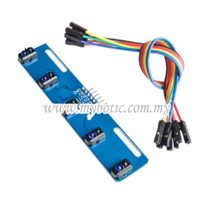
Description
This module is specialized for Arduino mobile robot that are to be used to run through a black and white line road track, or in simple words a module for line following robot. It uses a hex inverter that can provide clean digital output when there is a black line detected.
Features
- 5-way reflective optical sensors mounted in line (TCRT5000 or equivalent)
- On-board hex inverter provide clean digital output
- Sensitive to dark color and infrared
- Operating Voltage : 5 V (recommended)
- Comes with M3 flexible mounting slot
Materials Preparation

In this tutorial, we are going to make a tutorial on how 5 Ways TCRT5000 Tracking Sensor Module works with Arduino coding. Thus, the materials needed to be prepared is listed as following:
- Arduino Uno
- Female to male jumper wire
- USB Cable Type A to B
Hardware Installation
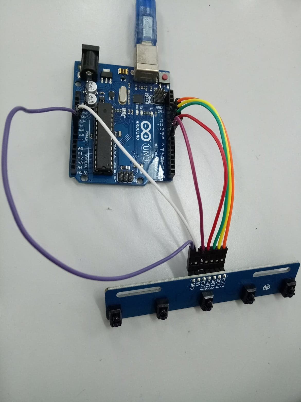
The diagram above shows the connection between 5 Ways TCRT5000 Tracking Sensor Module and Arduino Uno. The detailed connection will be mentioned below:
- OUT5 > D12
- OUT4 > D11
- OUT3 > D10
- OUT4 > D9
- OUT5 > D8
- 5V > 5V
- GND > GND
After completing the connection, simply connect Arduino Uno to power supply/PC via USB Cable Type A to B.
Source Code
- Download the source code provided and open it with Arduino IDE.
- Upload the source code into your Arduino Uno.
Downloads
Results
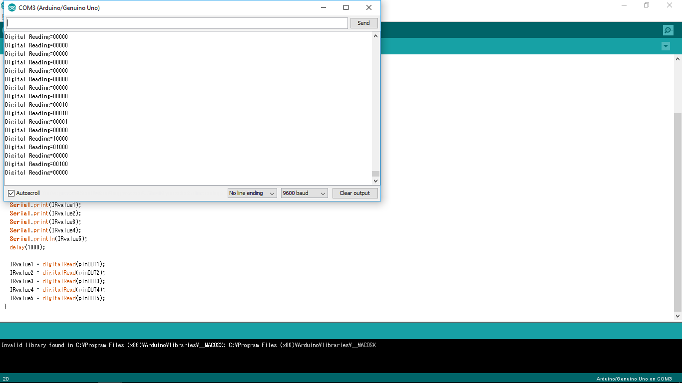
Based on the source code, the pins of OUT1, OUT2, OUT3, OUT4 and OUT5 are defined and each of them responds with IRvalue respectively. Serial monitor is set as 9600 baud and the results will be printed on the serial monitor.
How does it works?
Simply use your finger to approach the IR sensor. The IR sensor will detect your finger and it eventually lights up the LED on the module. On the serial monitor, when the IR sensor does not detect anything, the number will be shown as 0 and when it does detect, the number is 1.
Serial monitor will show "DigitalReading=00000" and those positions for 0 indicates which pin it is detected. For example, if the IR sensor 2 is detected, the serial monitor will show "DigitalReading=01000".