4G (LTE) Home Repeater With LimeSDR
by LimeMicro in Circuits > Wireless
32943 Views, 54 Favorites, 0 Comments
4G (LTE) Home Repeater With LimeSDR

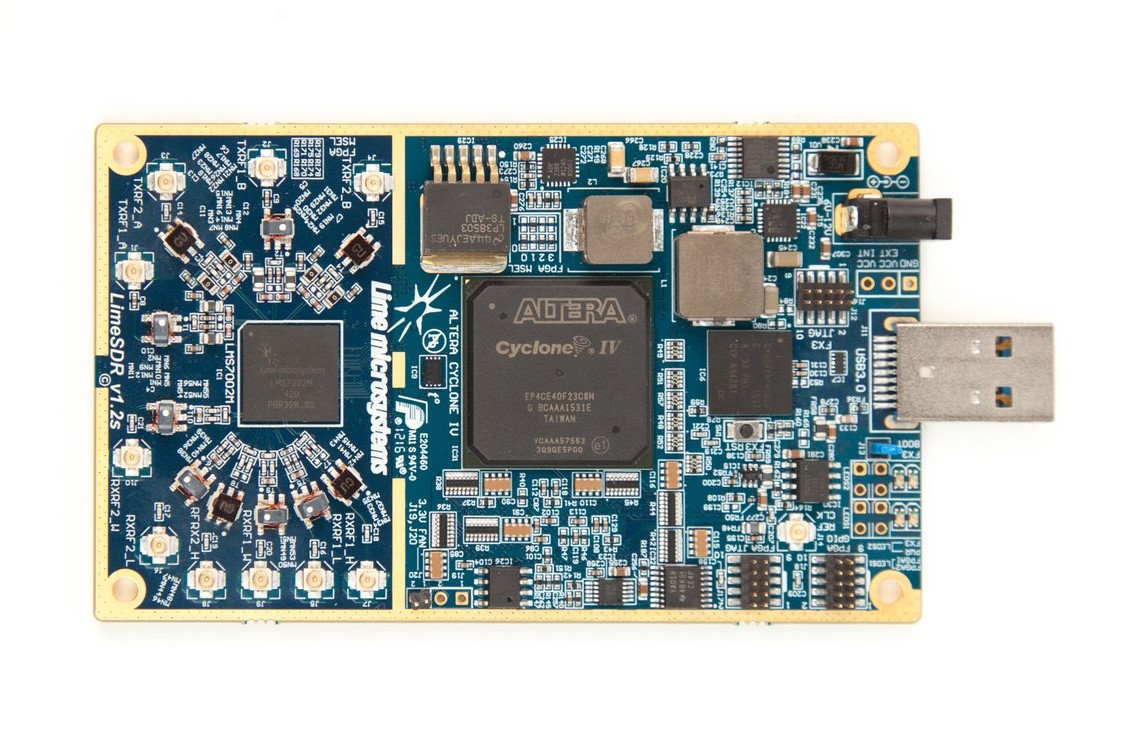
LimeSDR is a low cost, open source, apps-enabled software defined radio (SDR) platform that can be used to support just about any type of wireless communication standard.
LimeSDR can send and receive UMTS, LTE, GSM, LoRa, Bluetooth, Zigbee, RFID, and Digital Broadcasting.
It’s the first SDR to integrate with Snappy Ubuntu Core. This means you can easily download new LimeSDR apps from developers around the world. If you’re a developer yourself, you can share and/or sell your LimeSDR apps through Snappy Ubuntu Core as well.
These instructions show how to make LTE Home Repeater (Signal Booster) yourself using LimeSDR board.
4G (LTE) Repeater Components

1) Find out what is your 4G (LTE) band - different operators use different bands. In this tutorial I am using O2 (http://www.4g.co.uk/4g-frequencies-uk-need-know/) - it means 800 MHz (Band 20).
2) Check frequency details: https://en.wikipedia.org/wiki/UMTS_frequency_bands
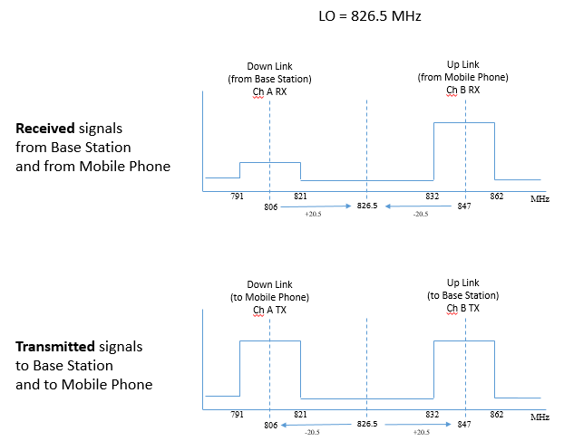
So it is Band 20 with Down-Link (signal from Base Station to mobile phone via LimeSDR board) 791 - 821 MHz and Up-Link (from mobile phone via LimeSDR to BaseStation) 832 - 862 MHz.
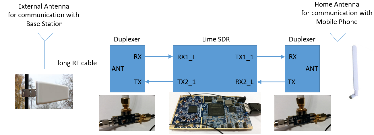
3) According to the block diagram repeater will consist of:
* Outdoor directional antenna (https://www.reichelt.com/LTE-UMTS-GPRS/DELOCK-8947...)
* Indoor antenna (https://www.amazon.co.uk/gp/product/B00RKMF678/ref...)
* 2x Band 20 Duplexer
* LimeSDR board (https://www.crowdsupply.com/lime-micro/limesdr)
4) Place outdoor antenna further away from indoor antenna (it comes with 5m cable)
How It Works

LimeSDR contains LMS7002 transceiver, it is MIMO - it means it has two channels, each channel has RX and TX (2x RX and 2x TX in total). And it contains one PLL for both RX in Channel A and B and one PLL for both TX in Ch A and B.
As different Mobile Operators are using different frequency bands and TX to RX separation will be also different, we will use universal configuration:
Channel A we will use to receive a signal from the Base Station and retransmit to Mobile Phone and Channel B to RX from Mobile Phone and TX to Base Station.
Now when we know frequencies (from the previous step), we can calculate Centre Frequencies and offsets:
Centre Freq for RX from BS to Phone: (791+821)/2 = 806 MHz (30 MHz bandwidth)
Centre Freq for TX from Phone to BS: (832+862)/2 = 847 MHz (30 MHz BW)
To keep configuration universal for all LTE bands, we will use only one PLL (TX PLL), that will set LMS7002 Centre frequency (LO), it will receive and transmit at this frequency:
LMS7002 LO: (806+847)/2 = 826.5 MHz
It means received IF (demodulated low freq component, without RF) signal frequency (Fin - Flo) will be from 791 - 826.5 = -35.5 MHz to 821 - 826.5 = -5.5 MHz (-20.5 MHz centre)
In RF terminology, when you receive not at the center frequency, it is called "Low IF", so now received bandwidth became (826.5 - 791)*2 = 71 MHz (wanted signal is in 30 MHz BW).
"Zero IF" is more efficient for digital signal processing, because you can work with narrower bandwidth (compared to "Low IF") and use lower sample CLK or get more taps for the digital filter. In this Demo we will not digitally process signal - just connect RX digital output to TX digital input (digital loopback).
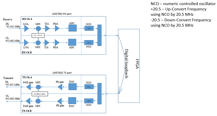
1) To work in "Zero IF" (when you receive in the middle of the band), we will shift it by +20.5 MHz to 0 using LMS7002 internal NCO (numeric controlled oscillator), it is called upconvert. So now our signal will be from -15 to +15 MHz (0 MHz center).
2) Then enable Digital loopback.
3) Now, when the signal is in TX chain, use NCO to shift it by -20.5MHz (to original), it is called downconvert. And the signal will be transmitted to mobile phone
4) Signal from mobile phone will be received by Channel B RX (847 MHz RFin), it means 20.5 MHz NCO downconvert for RX and upconvert for TX.
5) Signal from mobile phone is strong, so Ch B RX gains should be low.
Summary: calculate LO, calculate how much you need to shift by NCO. Channel A and B have same settings, except NCO upconvert/downconvert and gains.
Using Control Software

Install Windows drivers: https://github.com/myriadrf/Windows-drivers
Download LMS7002 control software: https://github.com/myriadrf/LimeSuite/tree/master/...
1) Options -> Connection Settings -> select USB3.0 (LimeSDR-USB)
2) Open -> select 4G_repeater.ini -> Press GUI->Chip (it will load all settings for LMS7002)
3) SXT tab -> type LO frequency, click Calculate and Tune
4) CLKGEN tab -> Press Calculate and Tune
5) Adjust RX gain in RFE tab - LNA, TIA and in RBB tab - PGA gain
6) Adjust TX gain in TRF tab - TXPAD gain control (put the same number for TXPAD linearizing part gain), in TBB tab - Frontend gain
7) In TxTSP and RxTSP tabs put NCO value and press Upload NCO
8) Modules -> FPGA controls -> select Digital loopback enable
9) Use "Network Cell Info Lite" app to measure received signal strength
Gain settings will depend on antennas isolation - transmitting antenna may overload receiver. So it is important to keep antennas as far as possible from each other and mount outdoor antenna behind the wall or on the roof.
Summary
1) Connect all hardware
2) Use control software
3) Open preset file. Change LO and NCO frequencies if needed
4) Adjust gain
Watch video tutorial: