3d Printed Crane Toy (Tinkercad)
by Josiah Miller in Workshop > 3D Printing
4311 Views, 71 Favorites, 0 Comments
3d Printed Crane Toy (Tinkercad)
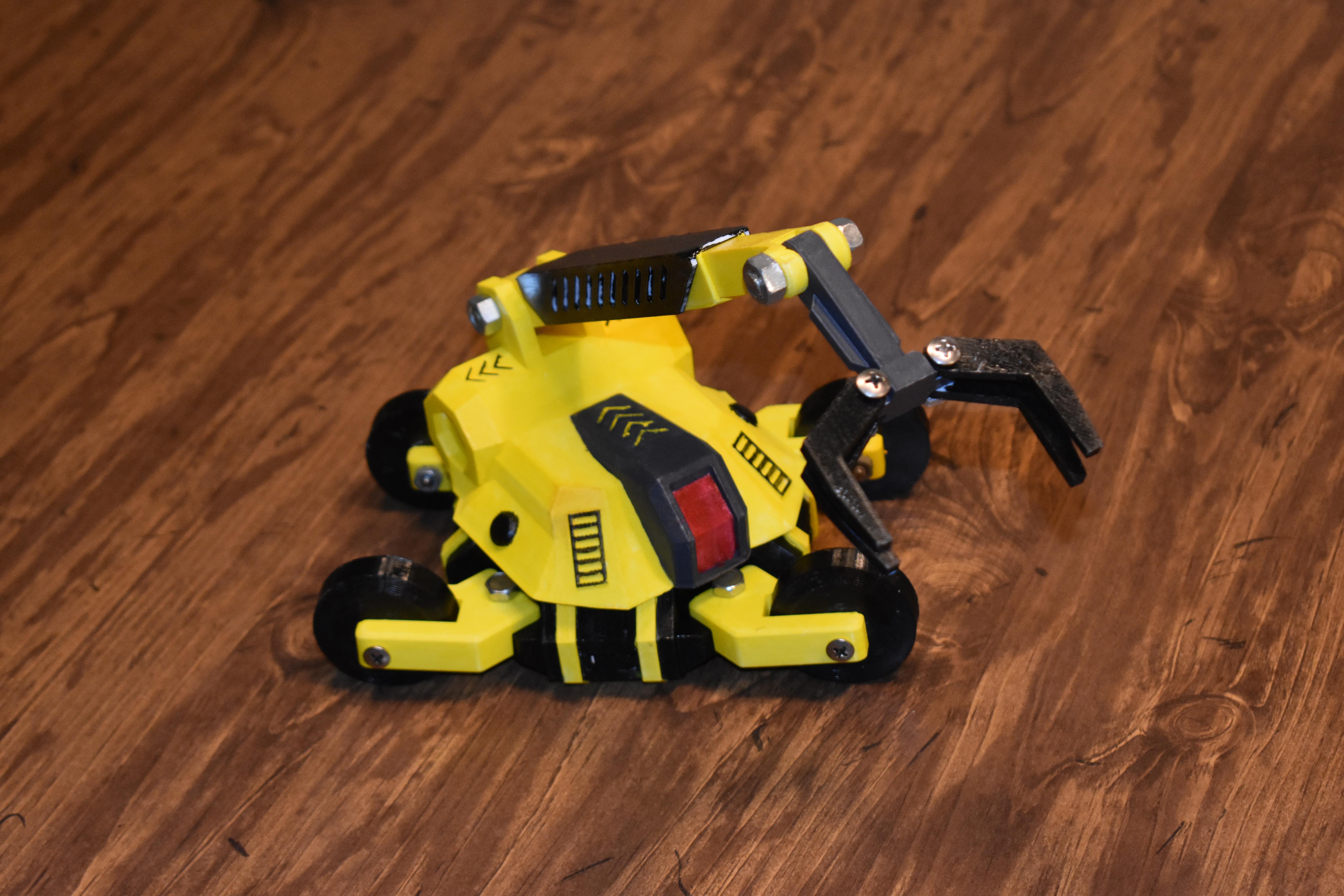
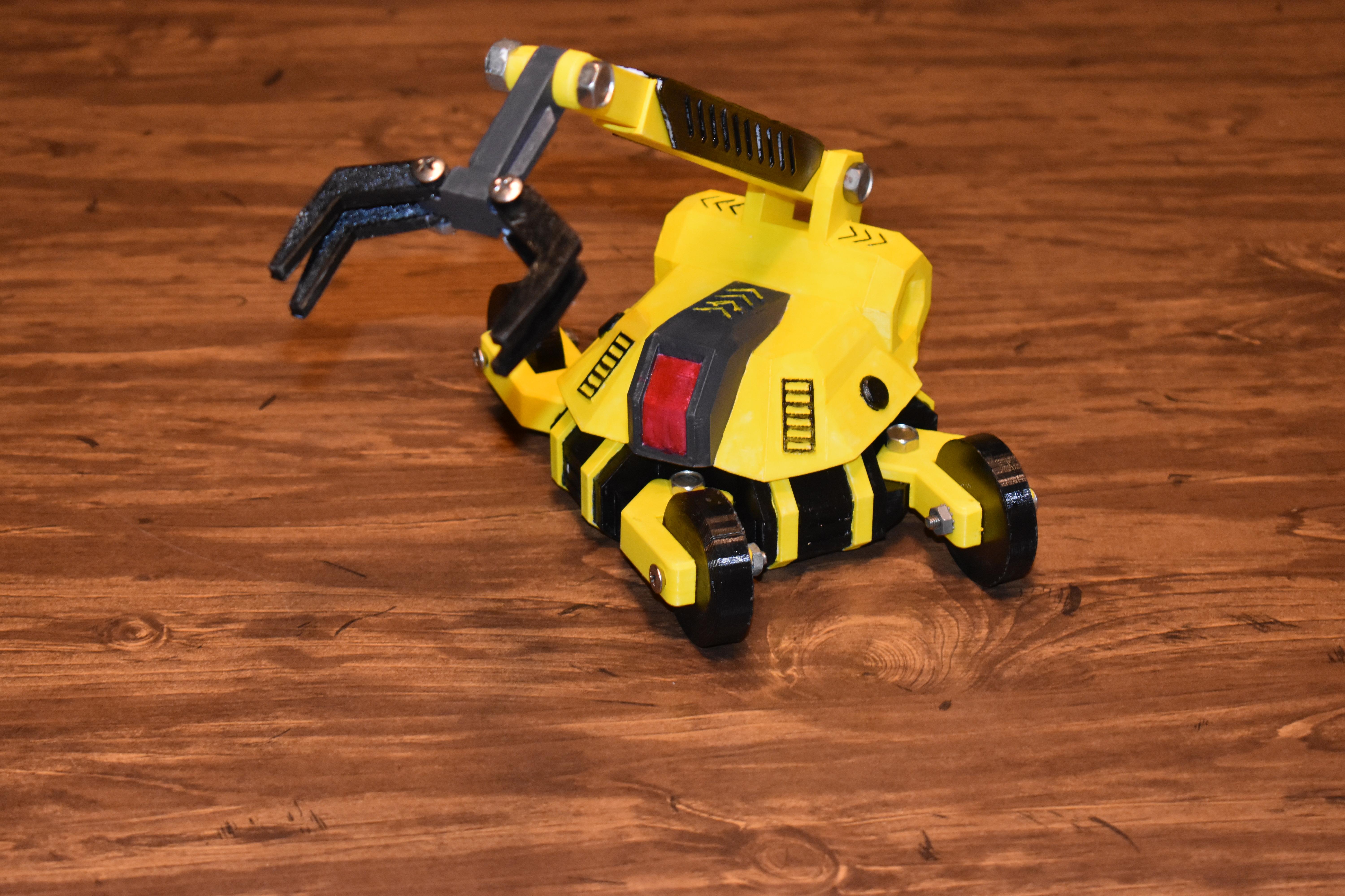
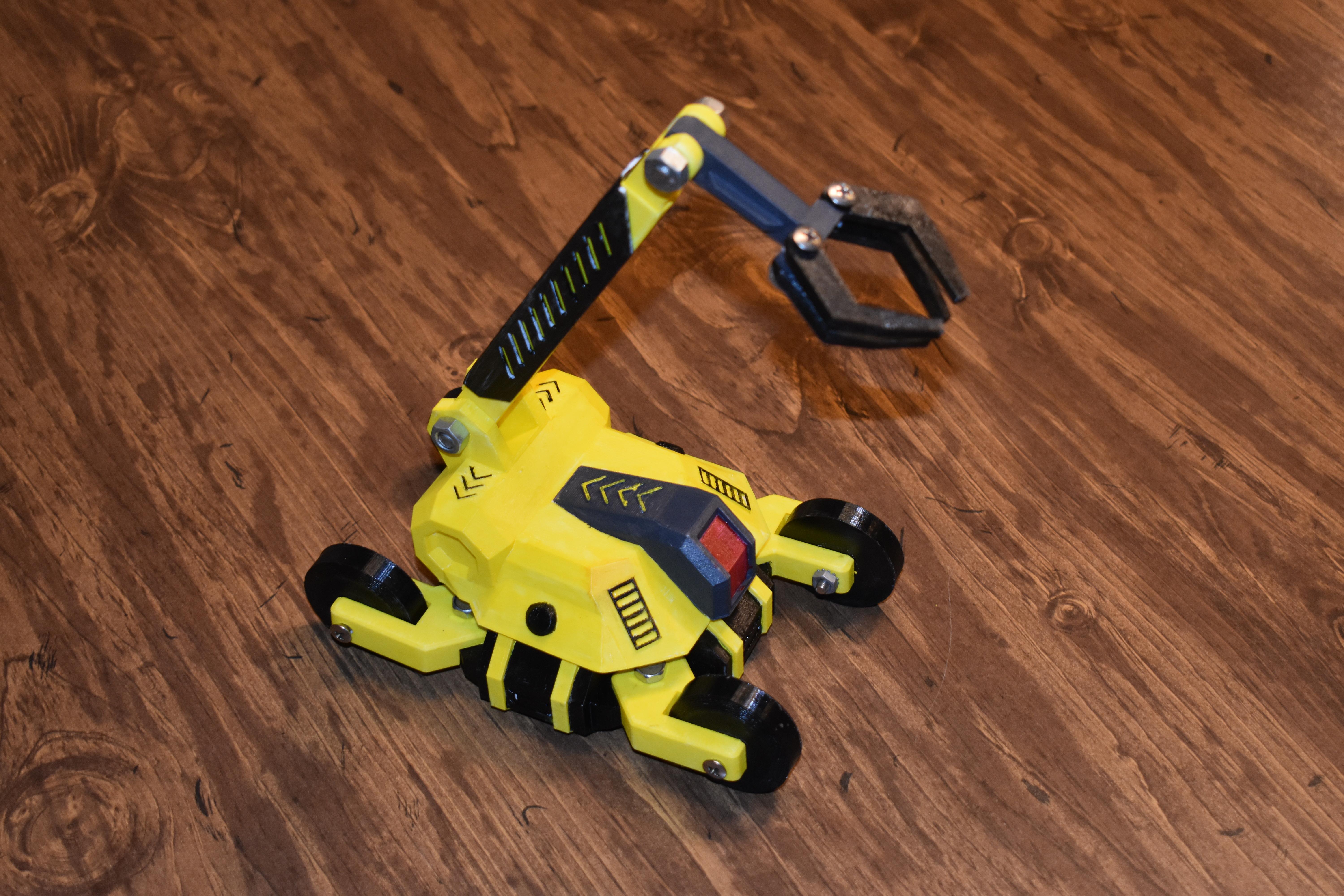
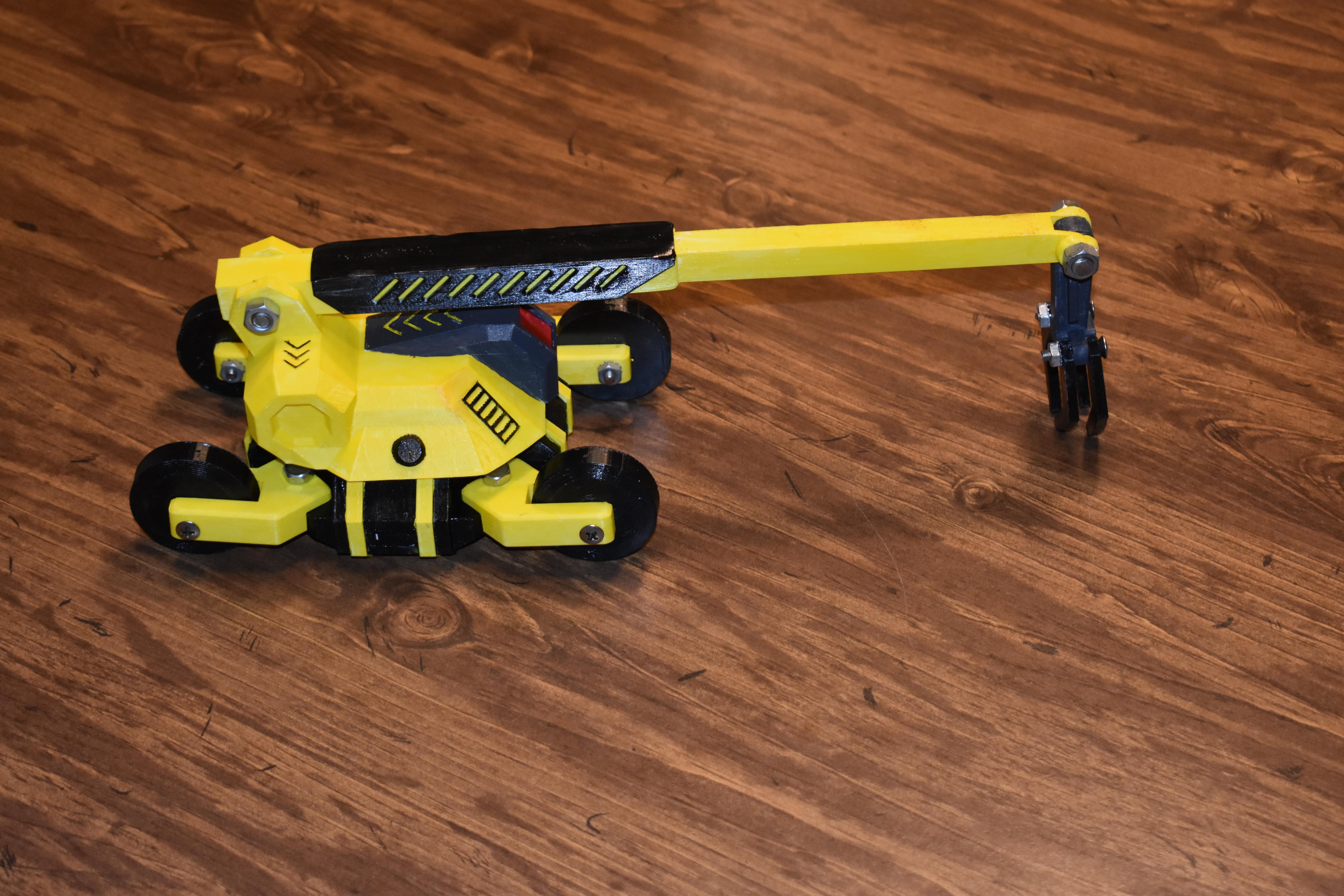
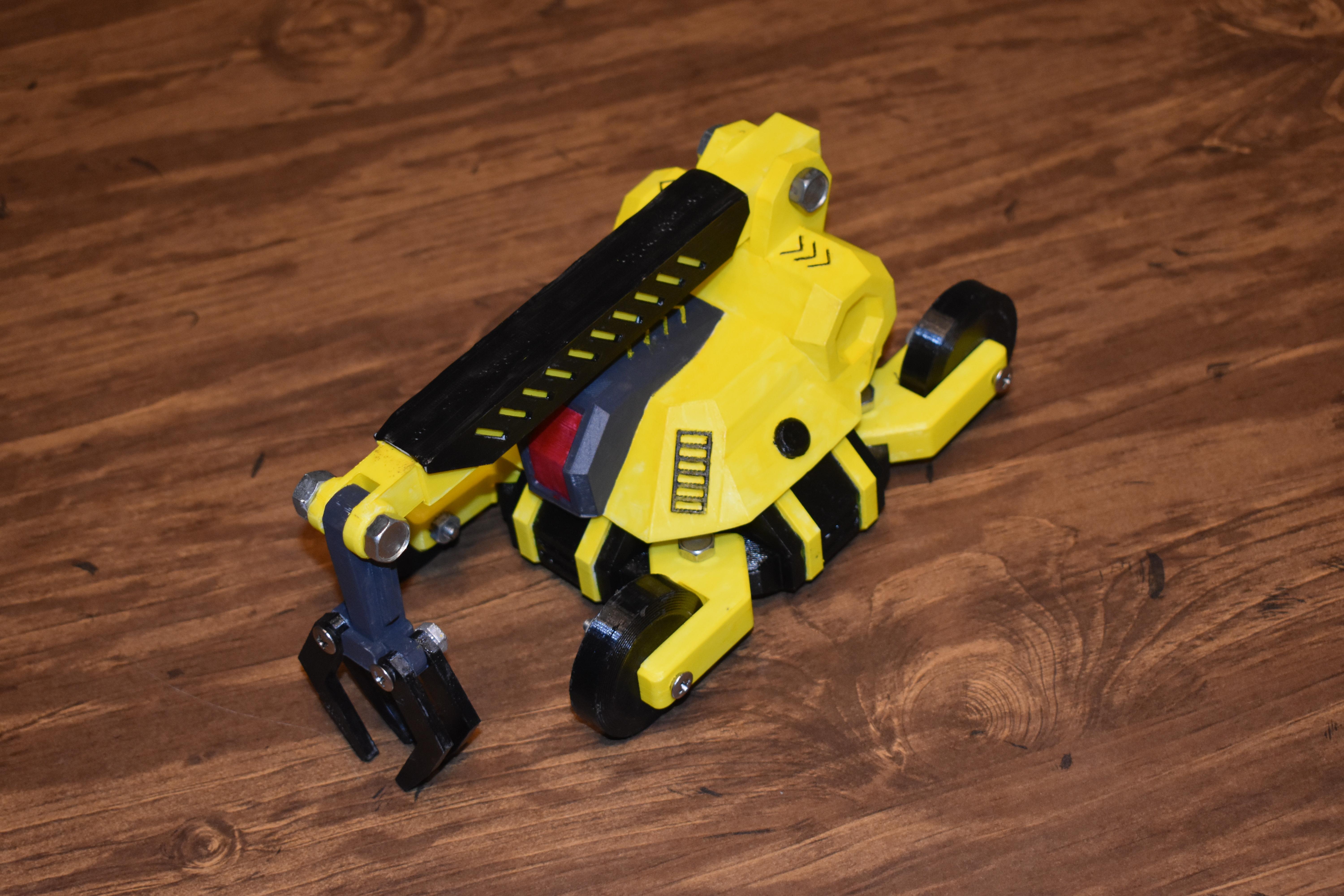
This is a toy made completely in Tinkercad and then 3d printed on my Ender 2 version 2. This is arguably the most detailed toy I have ever made and 3d printed, though many of my designs for animation or just for fun, have been more complex. This toy not only rolls on its 4 wheels, but the whole upper body spins a complete 360 degrees, the arm goes from level with the ground to about a 75 degree angle up, and then can also extend twice its own length. Furthermore, the claw itself rotates 180 degrees, and the individual "pinchers" move as well. you will probably need some nuts and bolts to attach this thing, but you can (if you want) 3d print connectors. I found them weaker and more difficult, it was more advantageous to go through our "junk bin" and find parts :) Anyhow I hope you love this project! Feel free to copy it in Tinkercad to find out how it works, or just download the stls from here and print it out!
disclaimer: neither Instructables nor myself is responsible for any injuries that may come through the reproduction of this toy. Ultimately it is build for ages 3 and up, but be careful if you do not connect the parts well, a bolt or nut may come off and become a choking hazard. I certainly don't want this toy, made so kids can have fun, turning into a cause of harm. so please be careful. :) thanks!
Here it is in Tinkercad.... https://www.tinkercad.com/things/7iZBoz3vsGO-3d-printable-crane-toy
Supplies
Computer, Tinkercad, pla, printer, and nuts and bolts. paint, (and paint brushes... you can try finger-painting it...but for some reason I don't think it will turn out like you expect... but hey... what ever floats your boat :)
CLAW
First we've got to make the claw, so.....
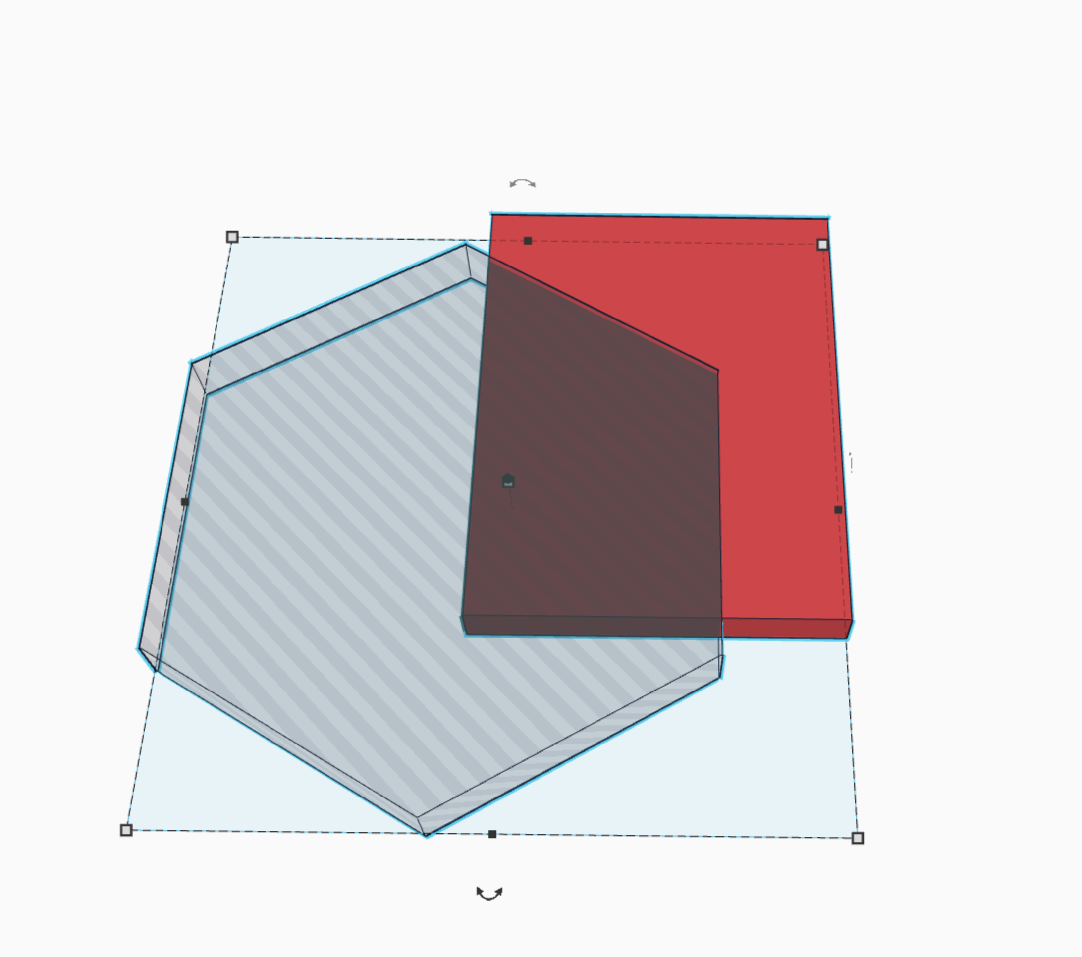
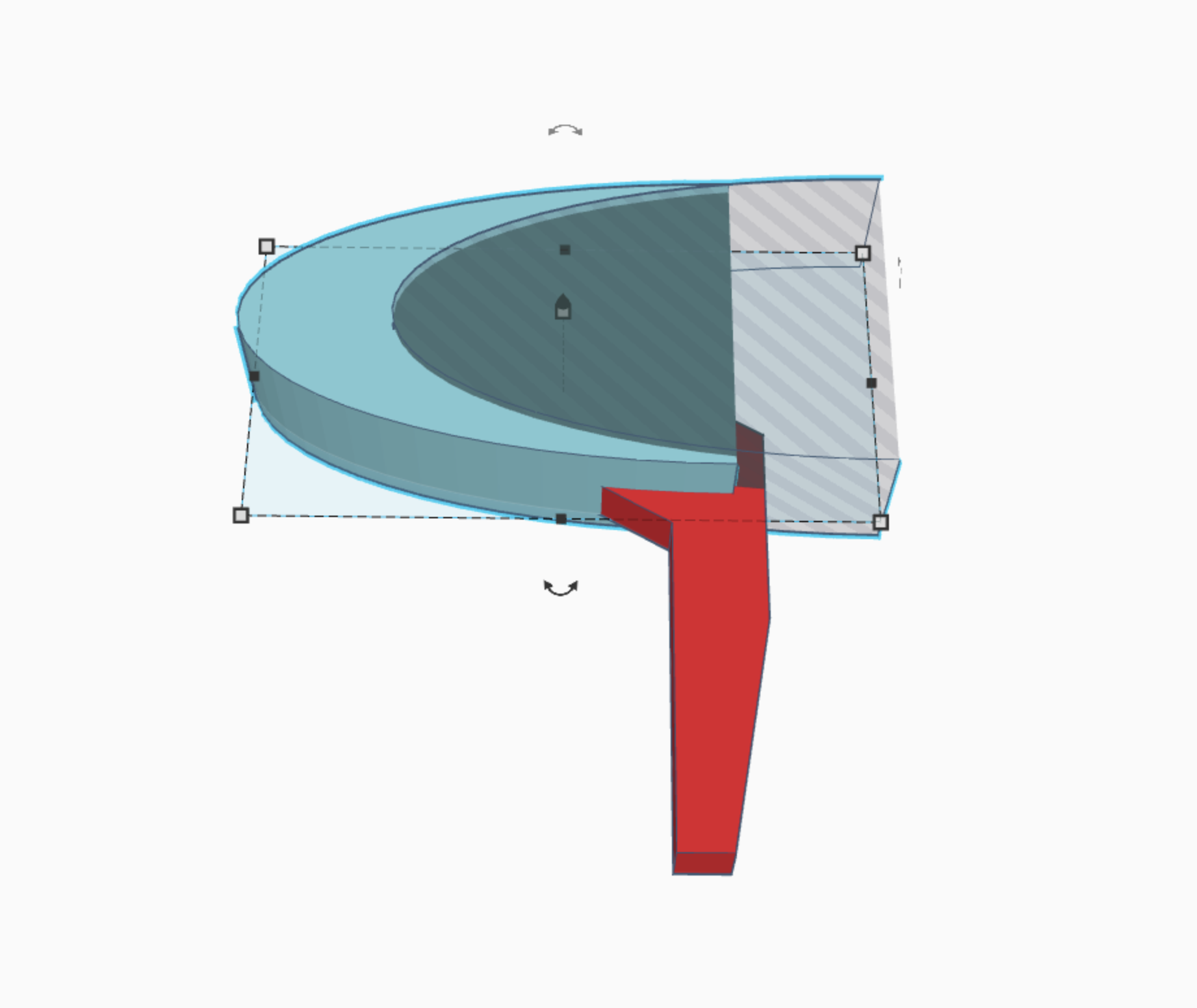
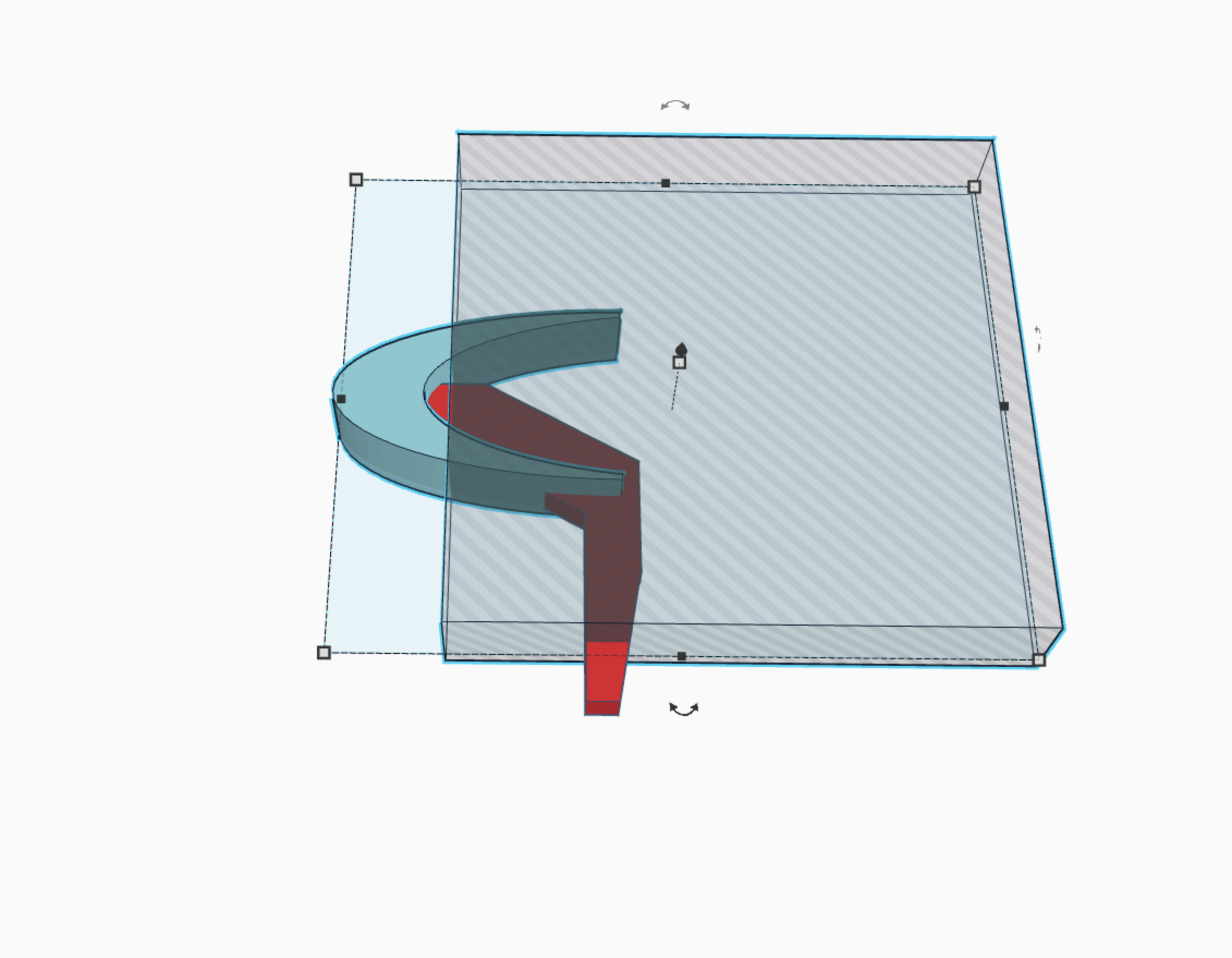
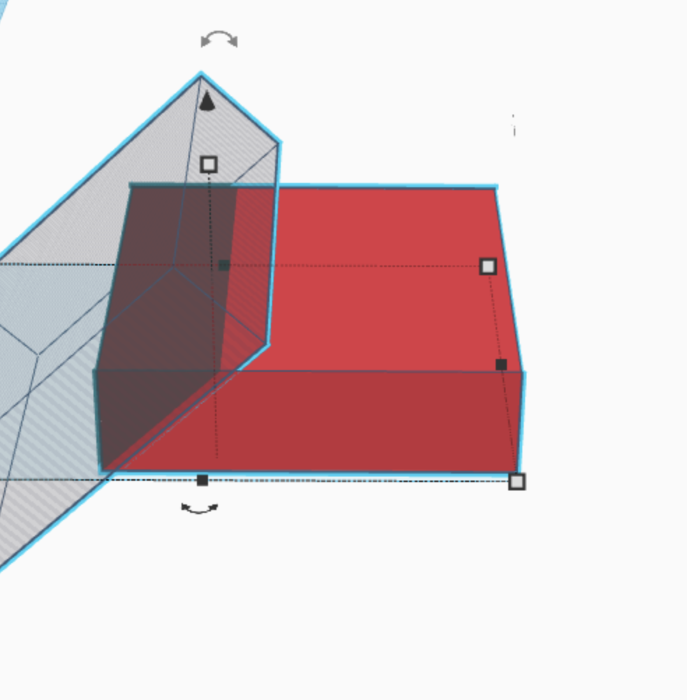
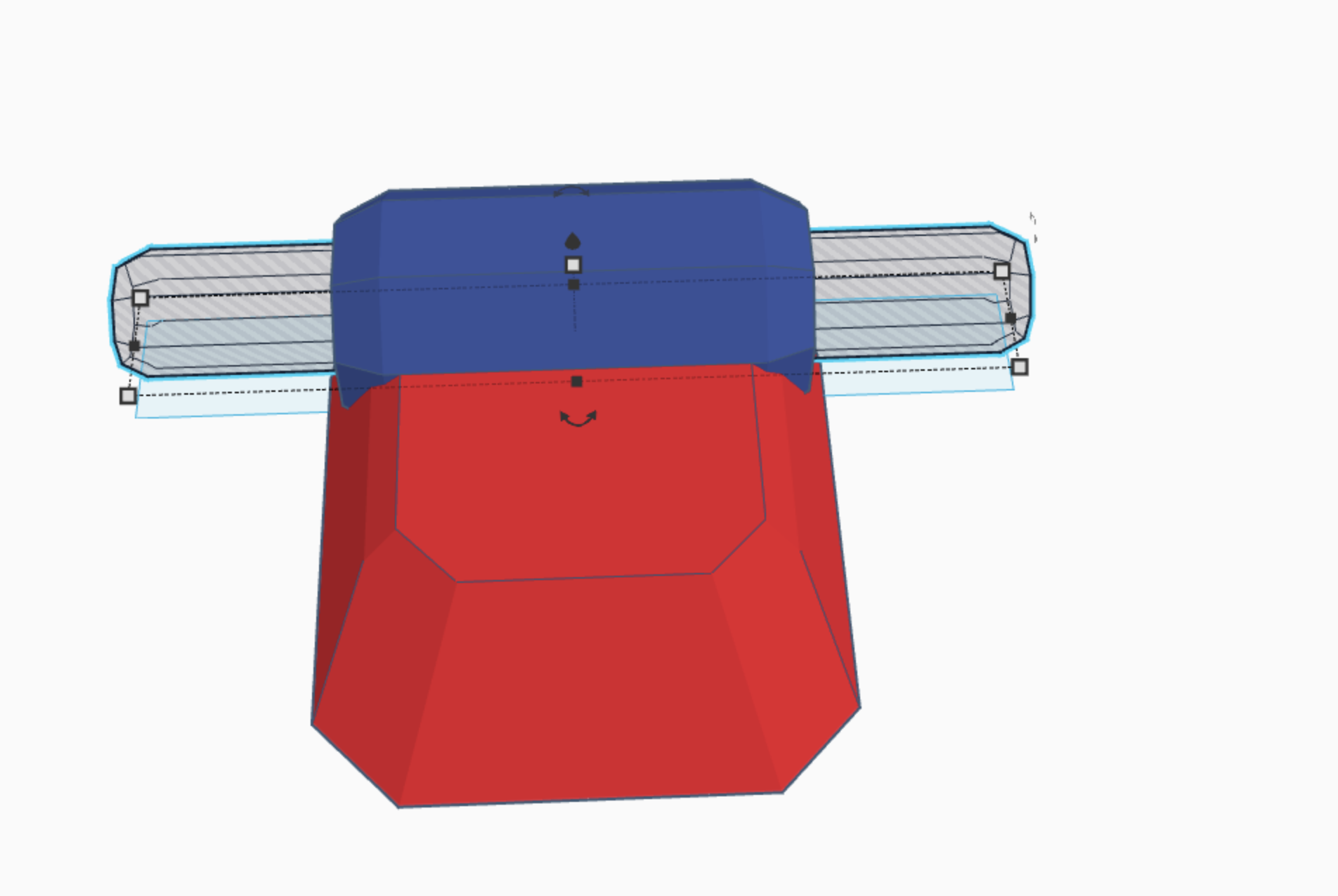
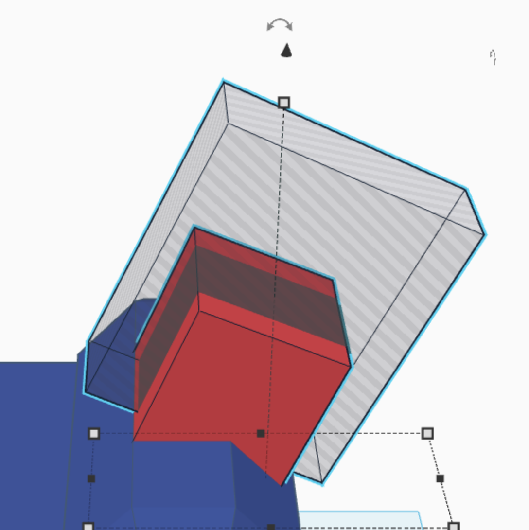
First, take a cube, and cut off the corner with a hexagon to make it a five sided shape as shown.
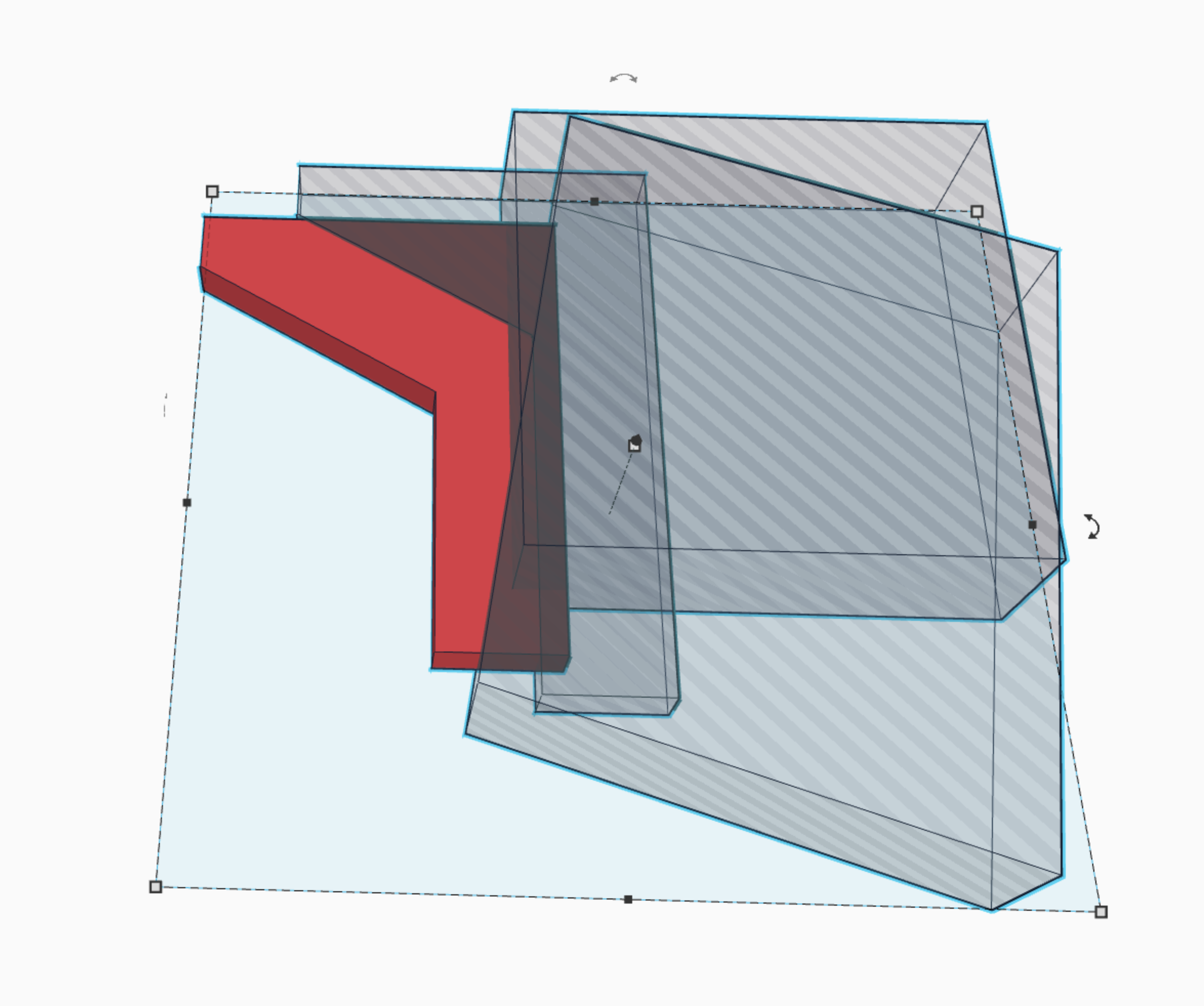
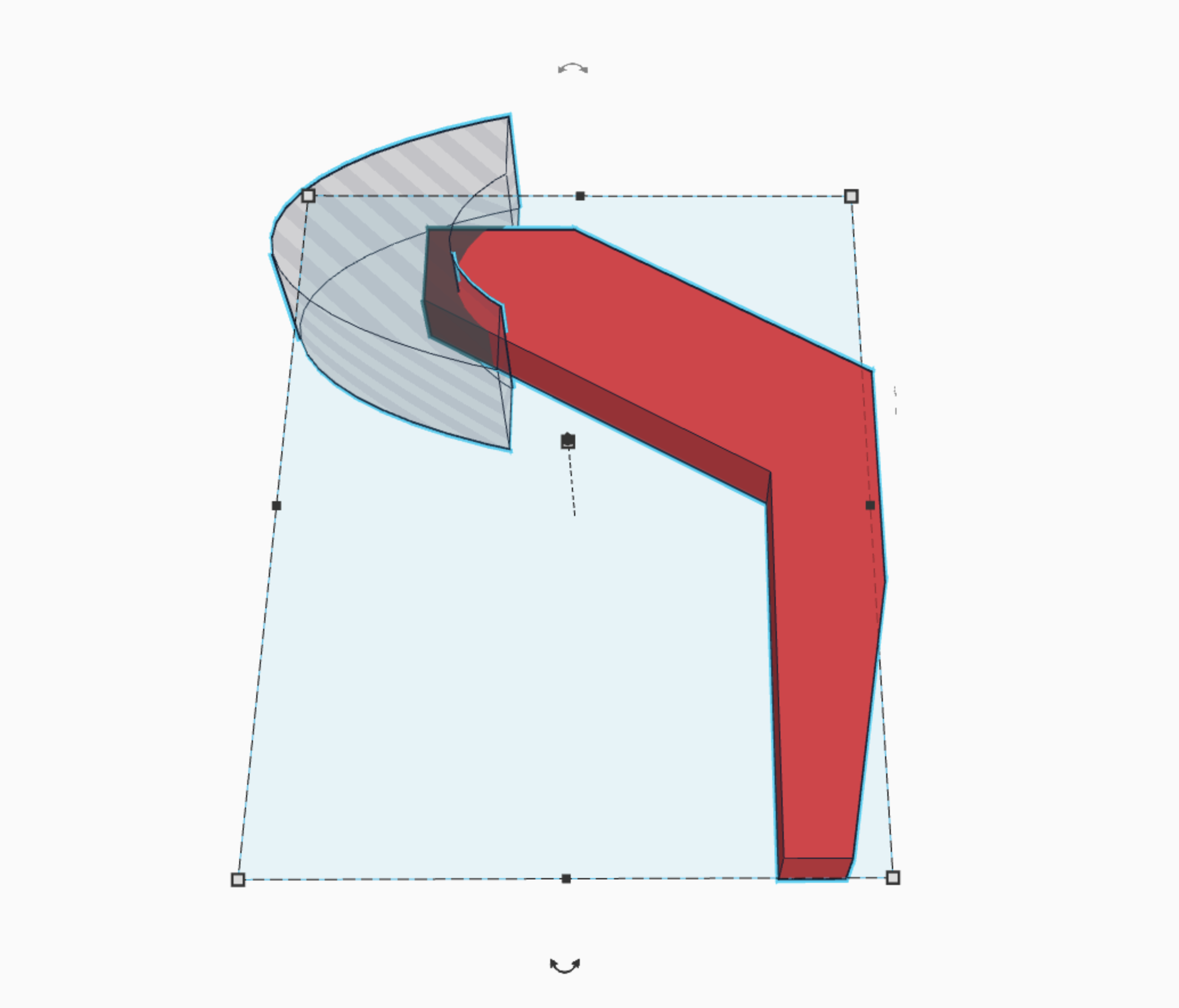
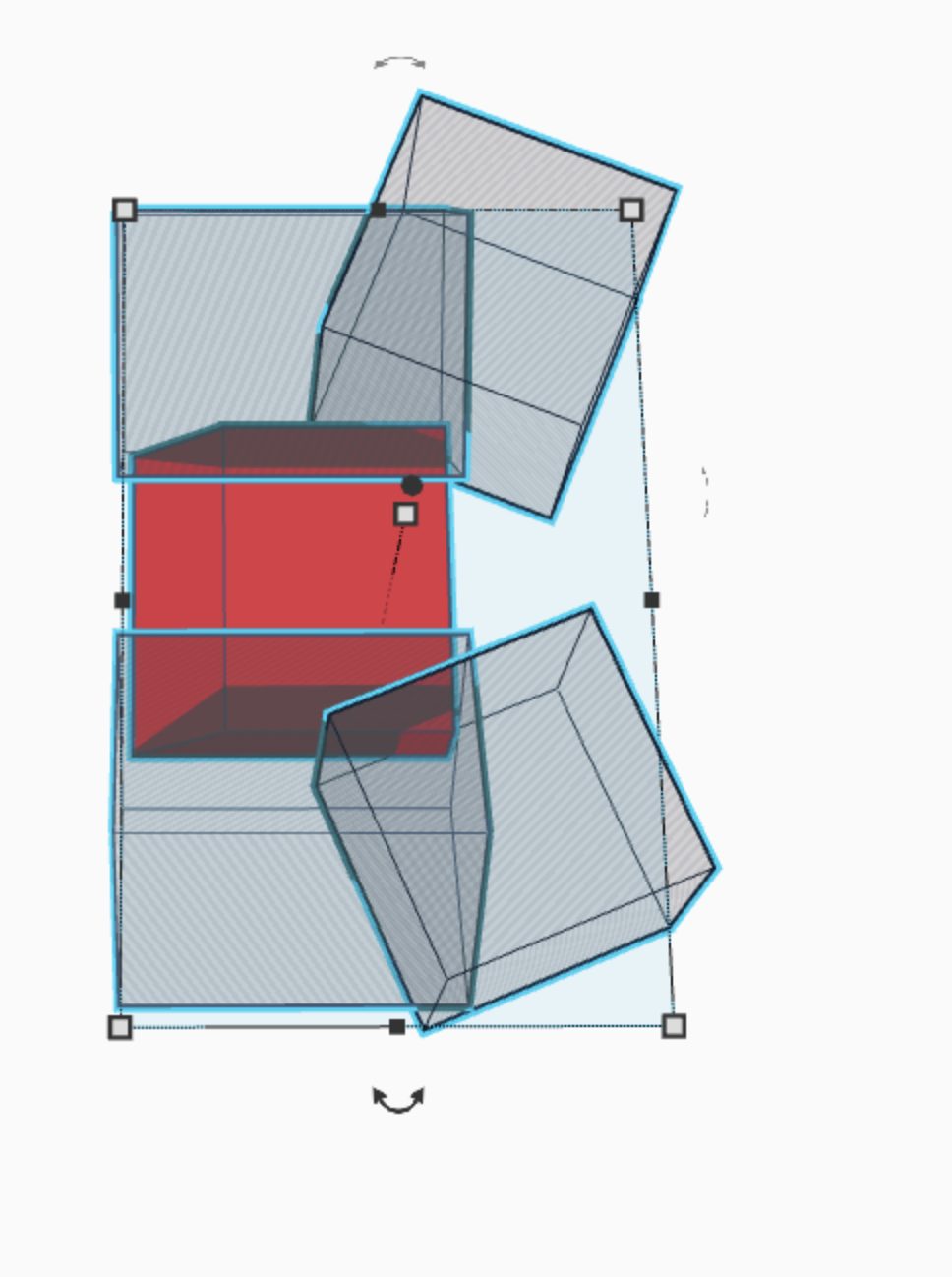
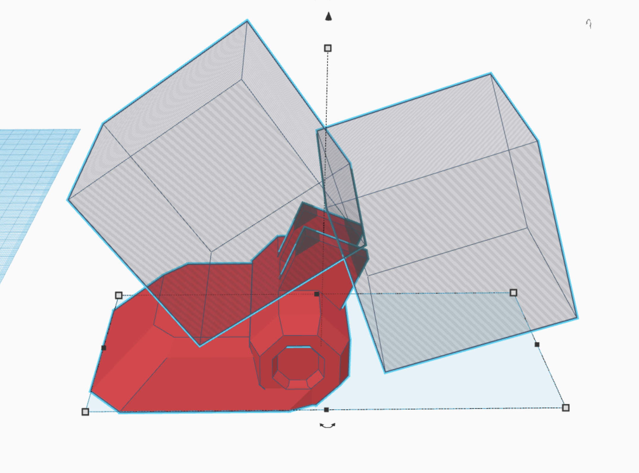
Second, take the shape you made, as well as two cubes, and but the claw into its basic shape, (picture 3)
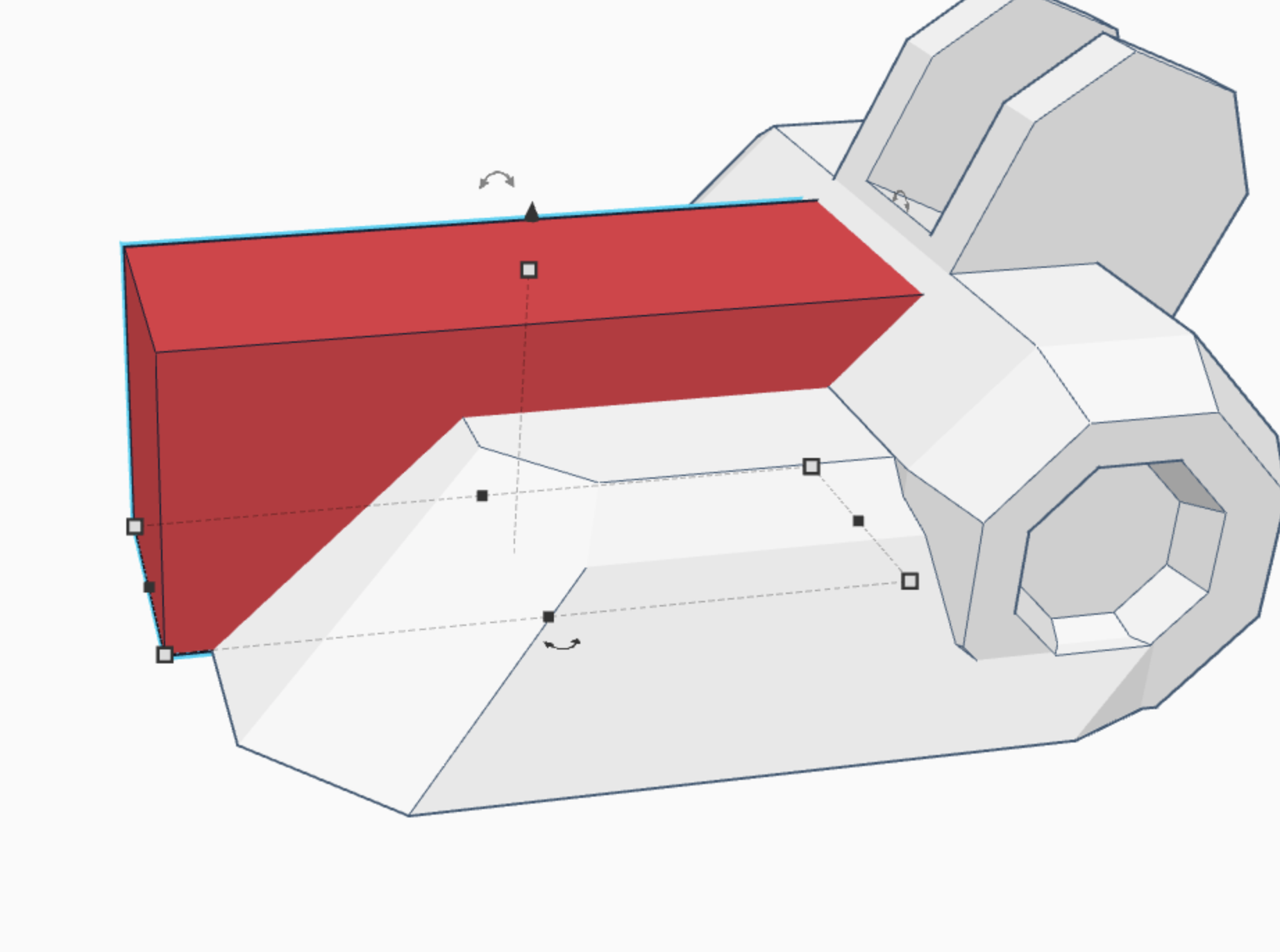
Third, take a round roof, shorten it along the y axis, and then duplicate it. Move it 1/4 of the way down the shape on the x axis, and group. (picture 4) {yeah its lots easier than it sounds XD :)
Fourth, take a cube and cut the ends off the round roof shape you made (picture 5)
Fifth, take that round roof, and trim the end off the claw, so that its rounded and will be able to move without getting caught. (picture 6)
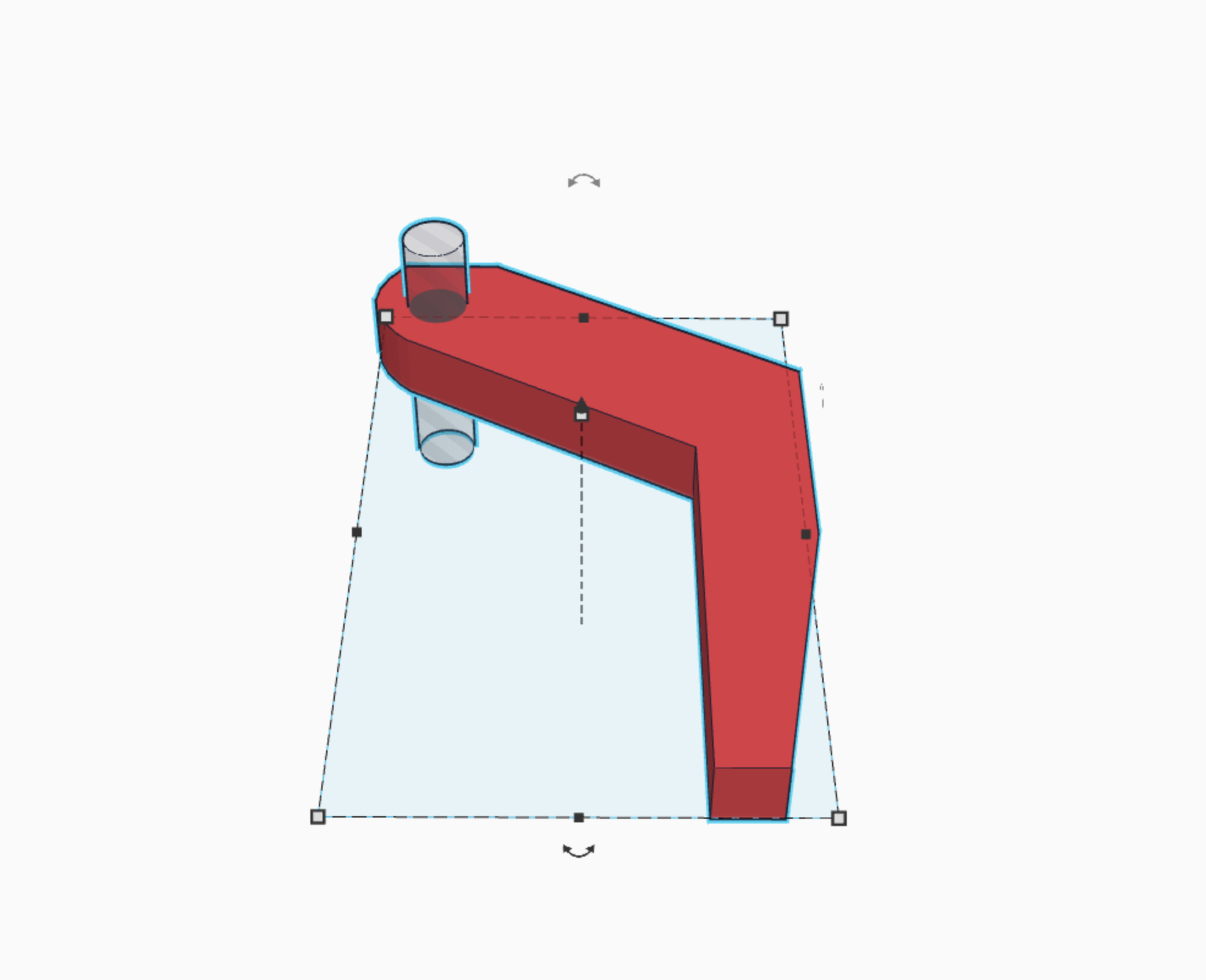
Sixth, take a cylinder to make a hole for the bolt to go through. (picture 7)
and you are done! you will need 4 claws, but since they are all identical, you can print this same shape 4 times. (just flip two of them over :)
Claw Holder?
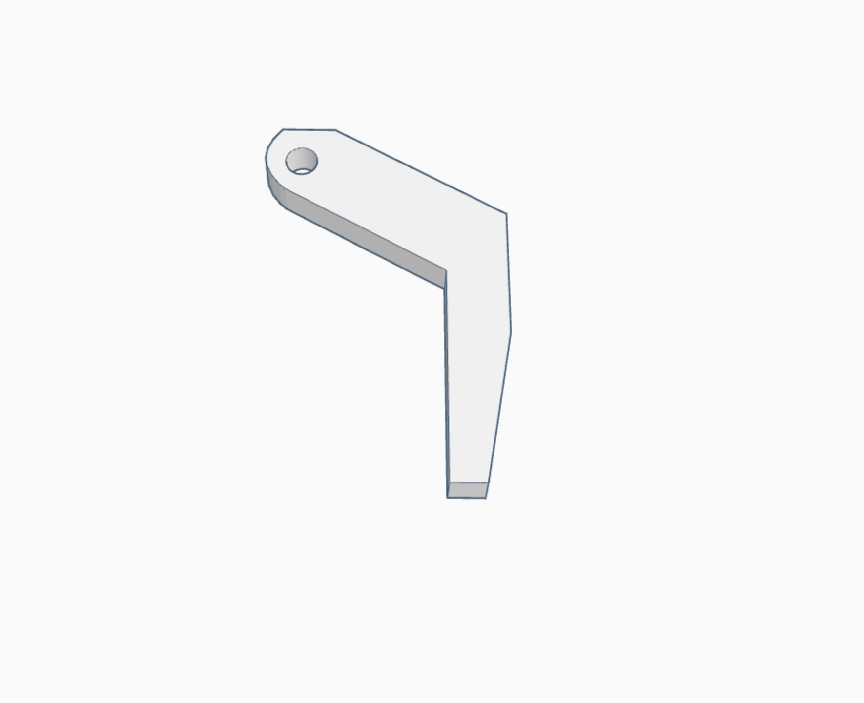
this is the little piece that holds the claws. It moves at about a 190 degree angle from the arm. call it a hand if you like :)
First, place a cube on the work plane and shorten it to half its height. then take two of the half roofs that I showed how to make in the first step, and round off the edges. (picture 2)
Second, take four cubes and place them equidistant in the four corners of the original cube and cut it to make a cross shape. (picture 3)
Third, take four cubes, rotate them at 45 degree angles, and then cut the original cube as shown to create a half beveled edge. (this step is for looks, picture 4)
Fourth, take two cylinders and cut holes in the curved out part of the original cube, to allow for the bolts that attach the claws. BE SURE TO MAKE THE CYLINDERS THE EXACT SAME SIZE AS THE ONES IN THE CLAWS! otherwise it won't work XD. (picture 5)
Fifth, take a second cube, and raise it above the original cube to make the "connector part" make sure the base of the cube is the same size as the bevel in picture 4. (picture 6)
Sixth, take a cylinder and hollow out the top part of the connector to hold a bolt. (picture 7)
Seventh, take another rounded roof shape, and smooth off the top. (picture 8)
Eighth, take a cube and cut off the edge of the connector piece so that it is at an angle up on just one side. (picture 9)
Ninth, add a hexagon in the center of the connector part as shown. (picture 10)
There you go! two pieces down! :)
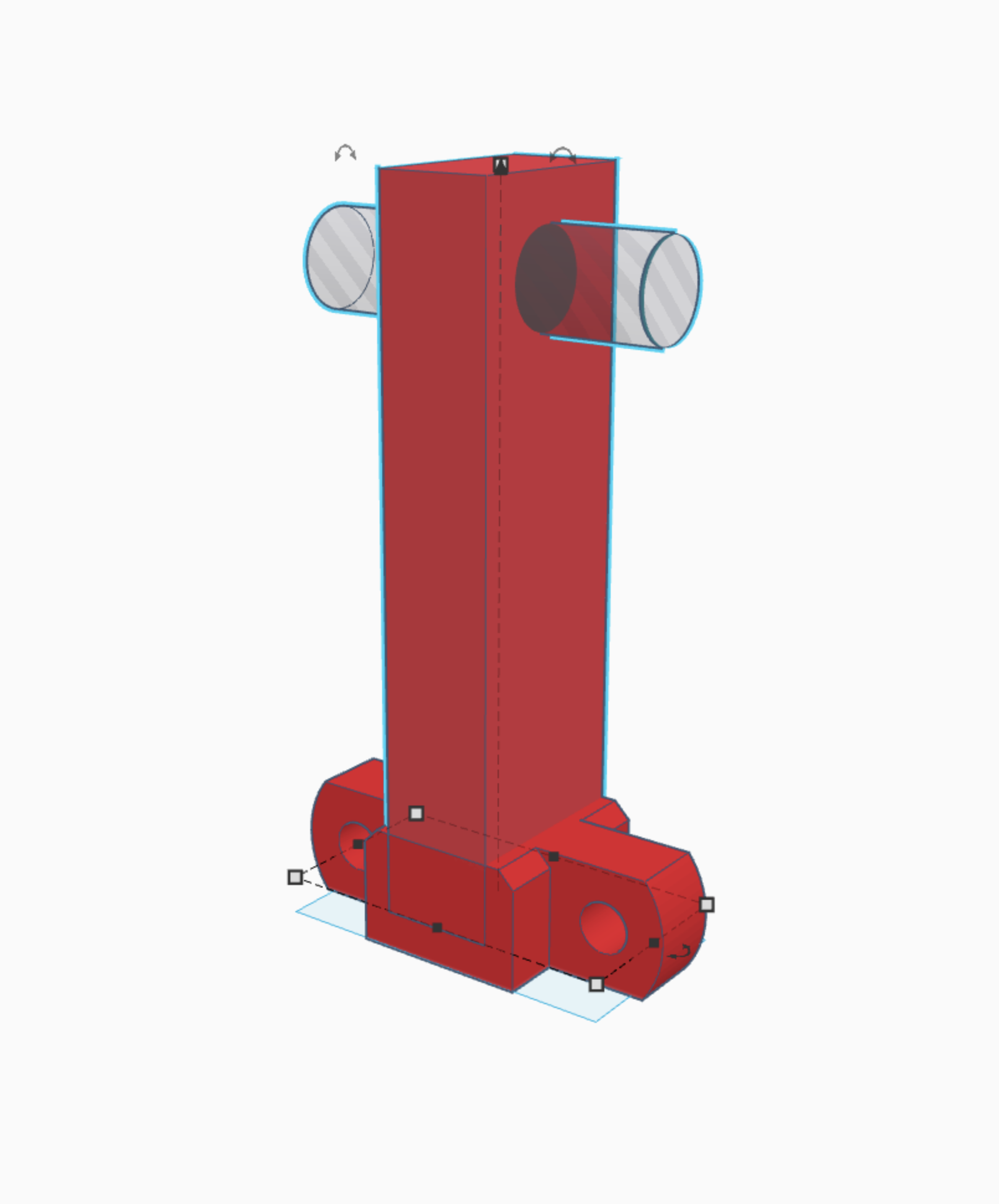
Extension Arm
This is the extension arm. It slots into a grove in the main arm to allow it to "extend" lol :)
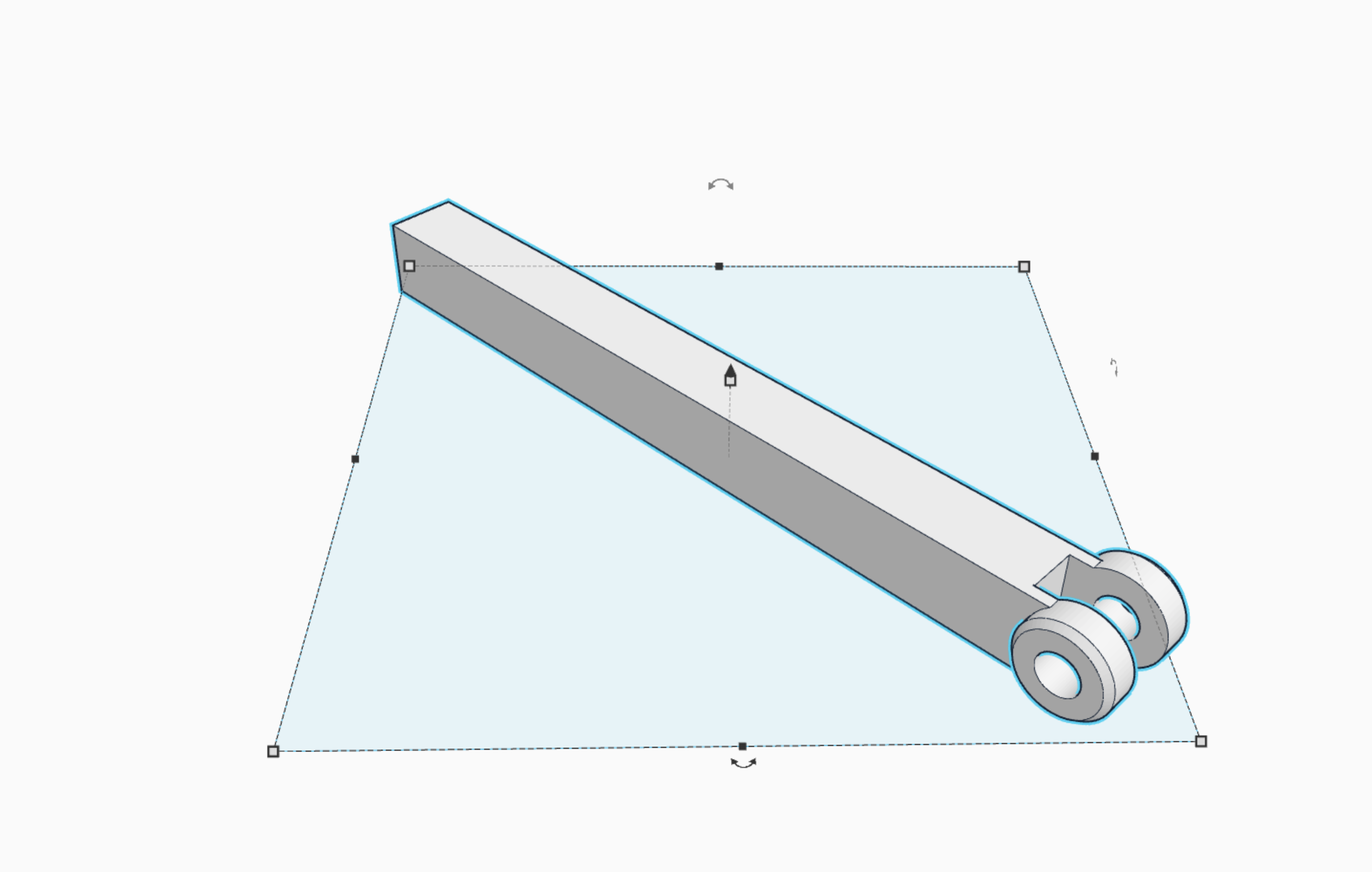
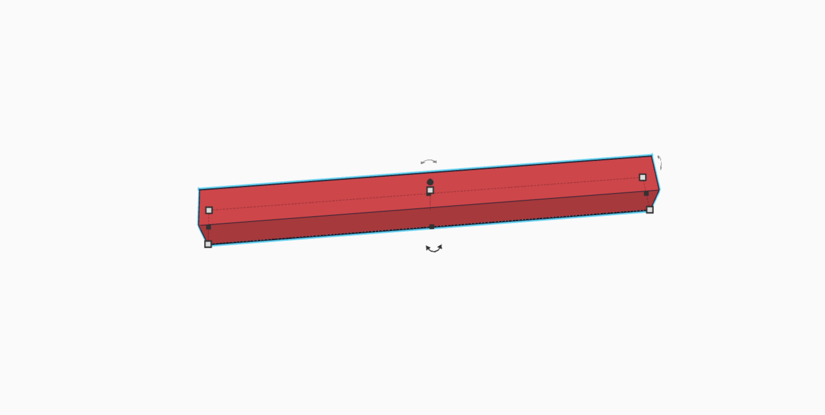
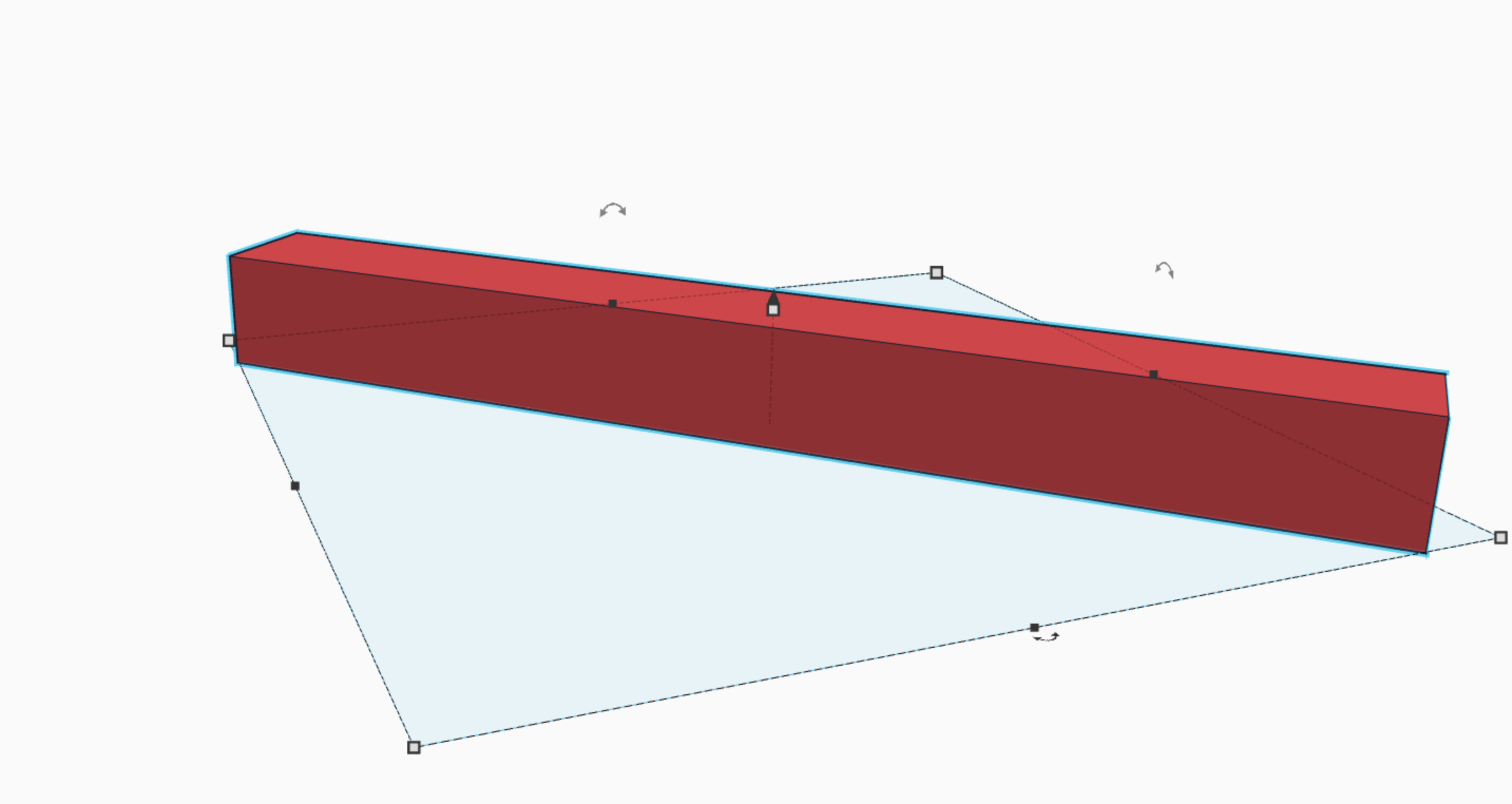
First, you need to get a cube and extend it about 6 times its previous length. (picture 2)
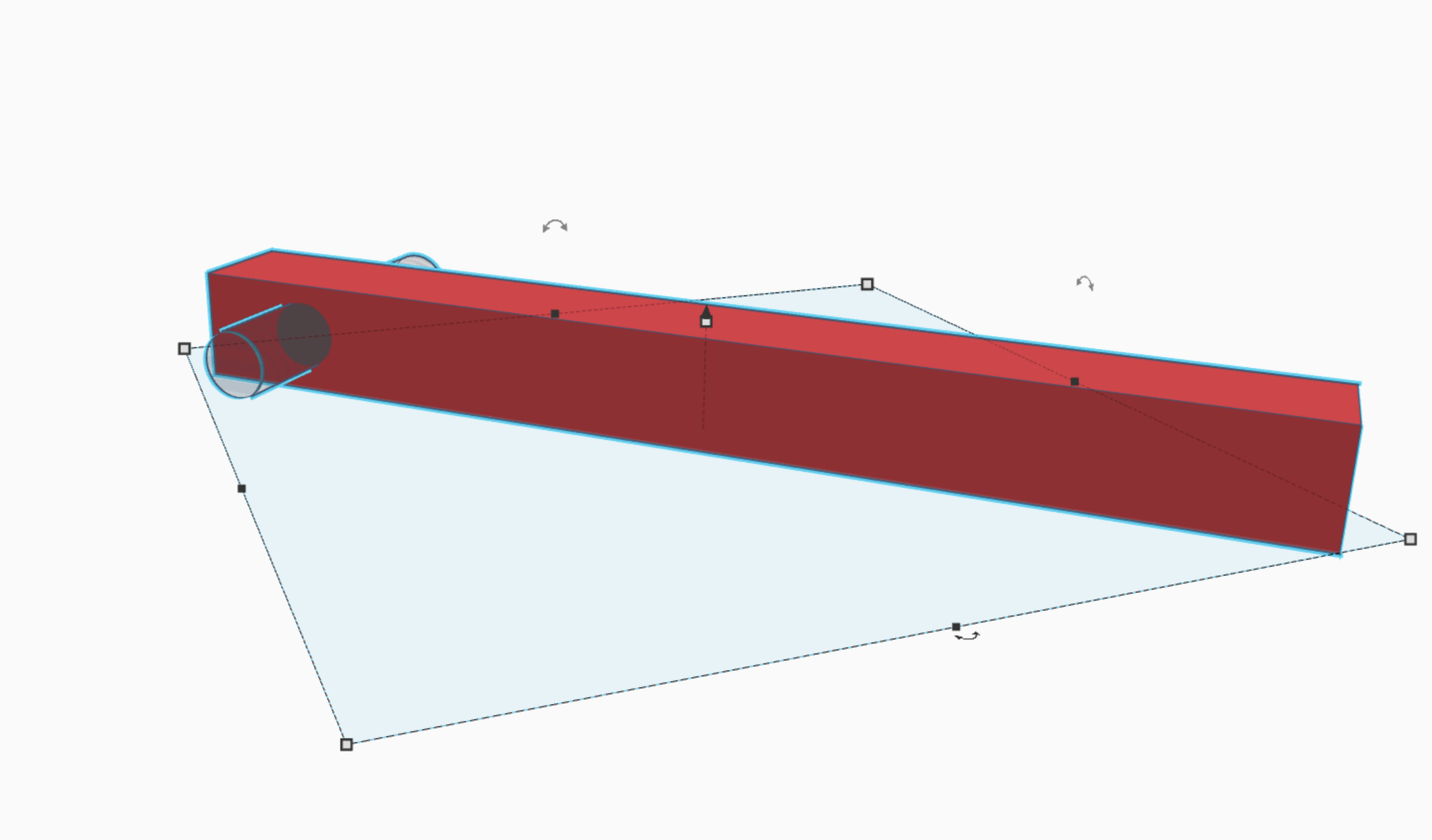
Second, take a cylinder, and turn the bevel on just a little bit, and then make it flush and centered with the original cube. it needs to be a little longer and taller as well. (picture 3)
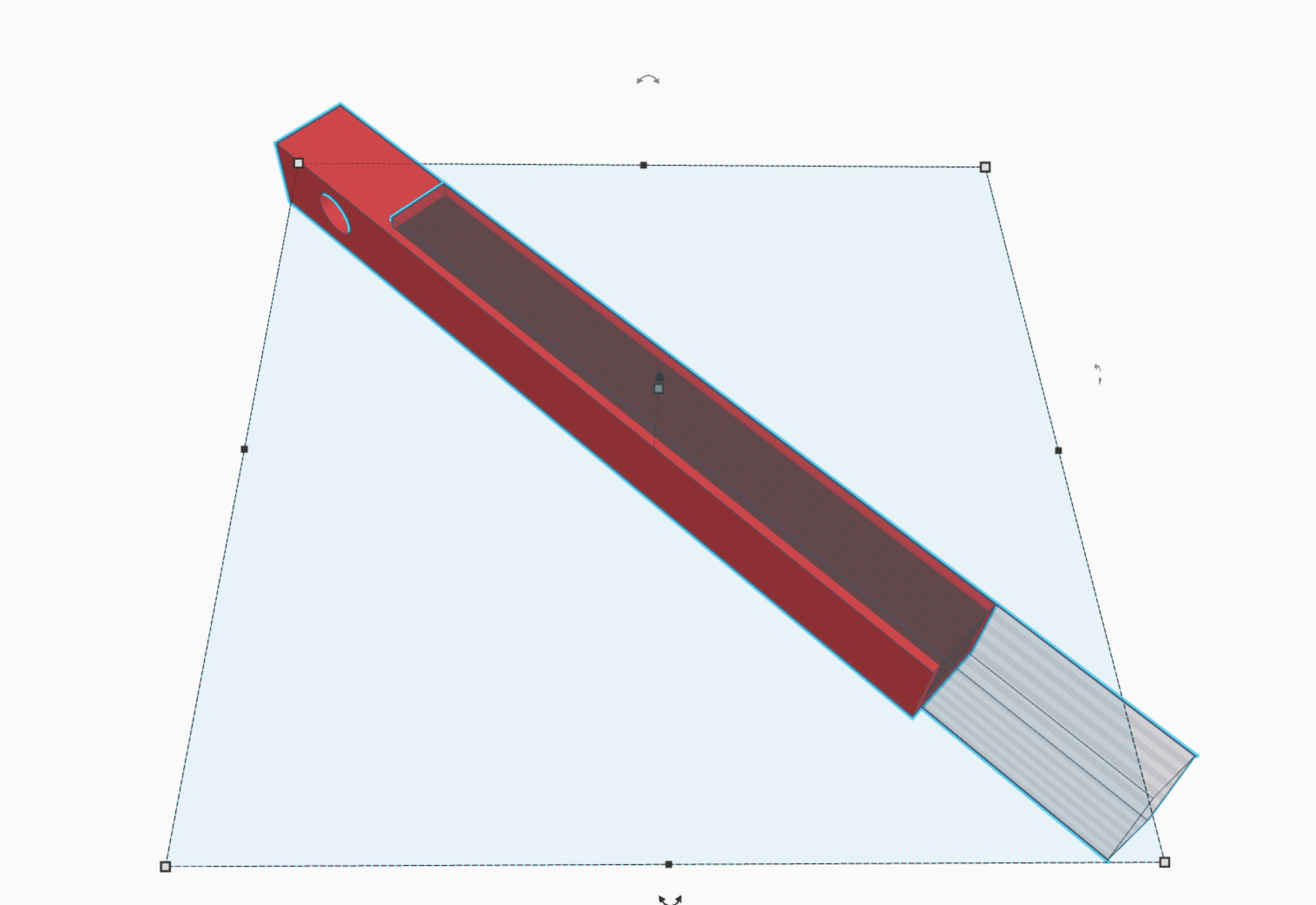
Third, take a cube, and cut a hole, that is about 3/4 the width of the original cube, directly through the cylinder. Also include whatever part of the original cube that intersects with the cylinder in that cut (make sure that the cube is the exact same size as the hand piece, or perhaps a millimeter larger, so that the hand piece can fit.) {see pervious step}. (picture 4)
Lastly take a cylinder and cut a hole in the original cylinder as shown, to make room for the bolt that attaches the "hand" make sure the cylinder is the exact same size as the one used on the hand piece or it will not work.
So there you go! an extension arm! :)
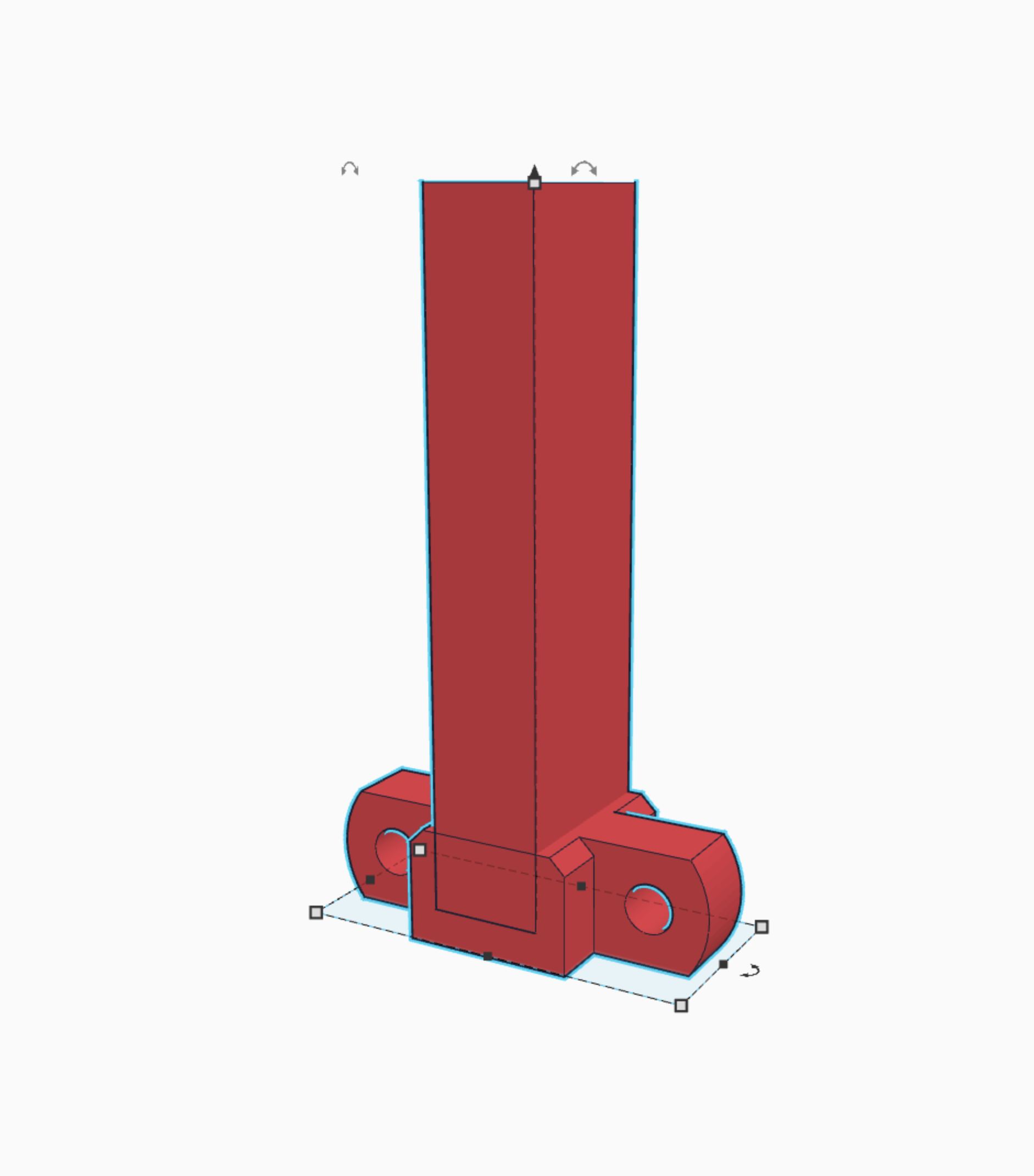
Arm (base)
Now were getting to the main part of the arm, the part that attaches to the main body!
First, make a cube, it must be bigger than the original cube from the last step. (picture 2)
Second, make a cylindrical hole in the end of the cube, so that a bolt can be threaded through and attached to the body. (picture 3)
Third, take the part from the last step, and cut a hole in the main cube. Then group it. This grove you made is where the extension arm will fit, allowing it to move in and out. (picture 4)
and there you go! next part! :)
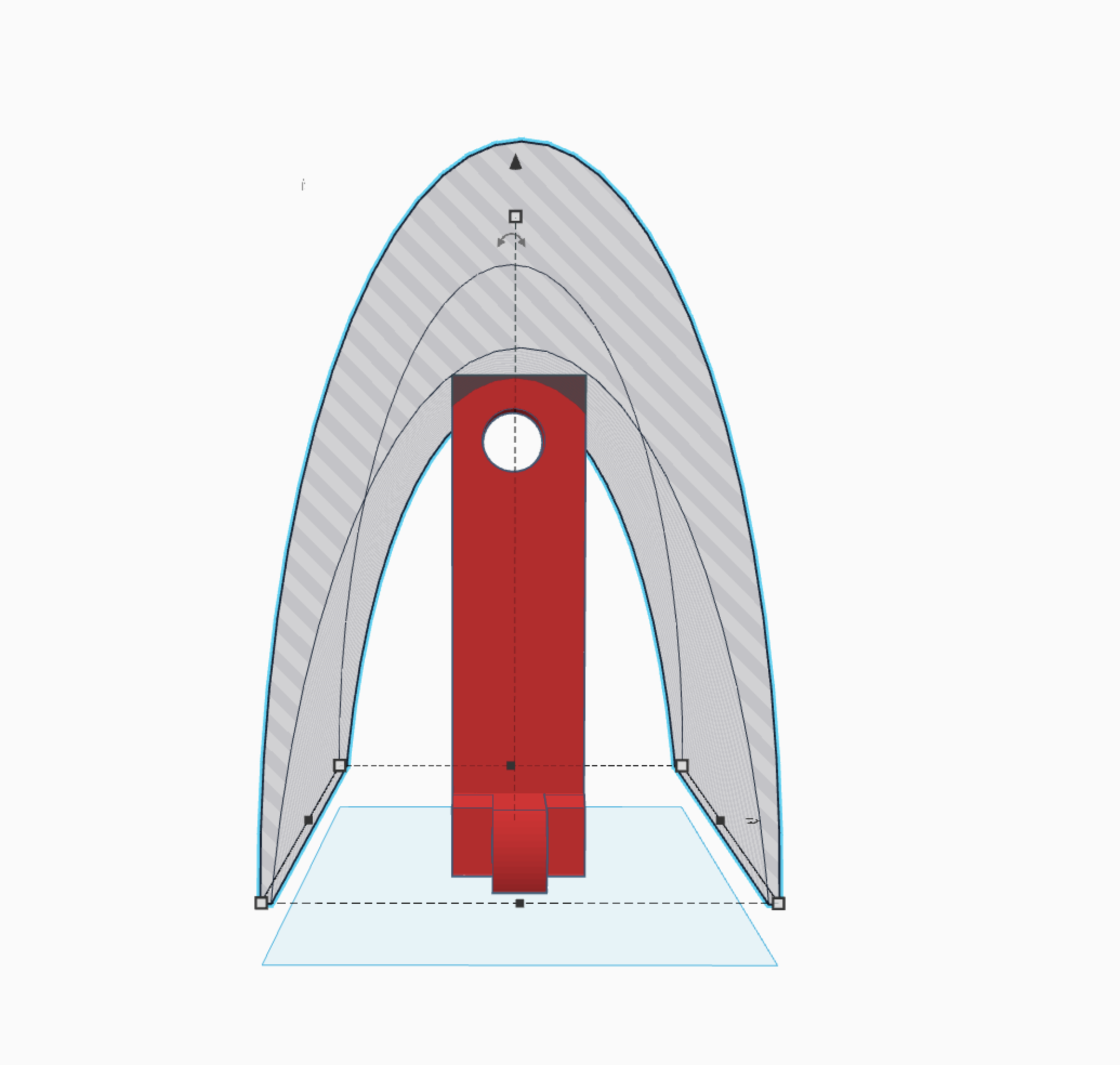
Top Part of the Arm.
This part holds in the extension arm.
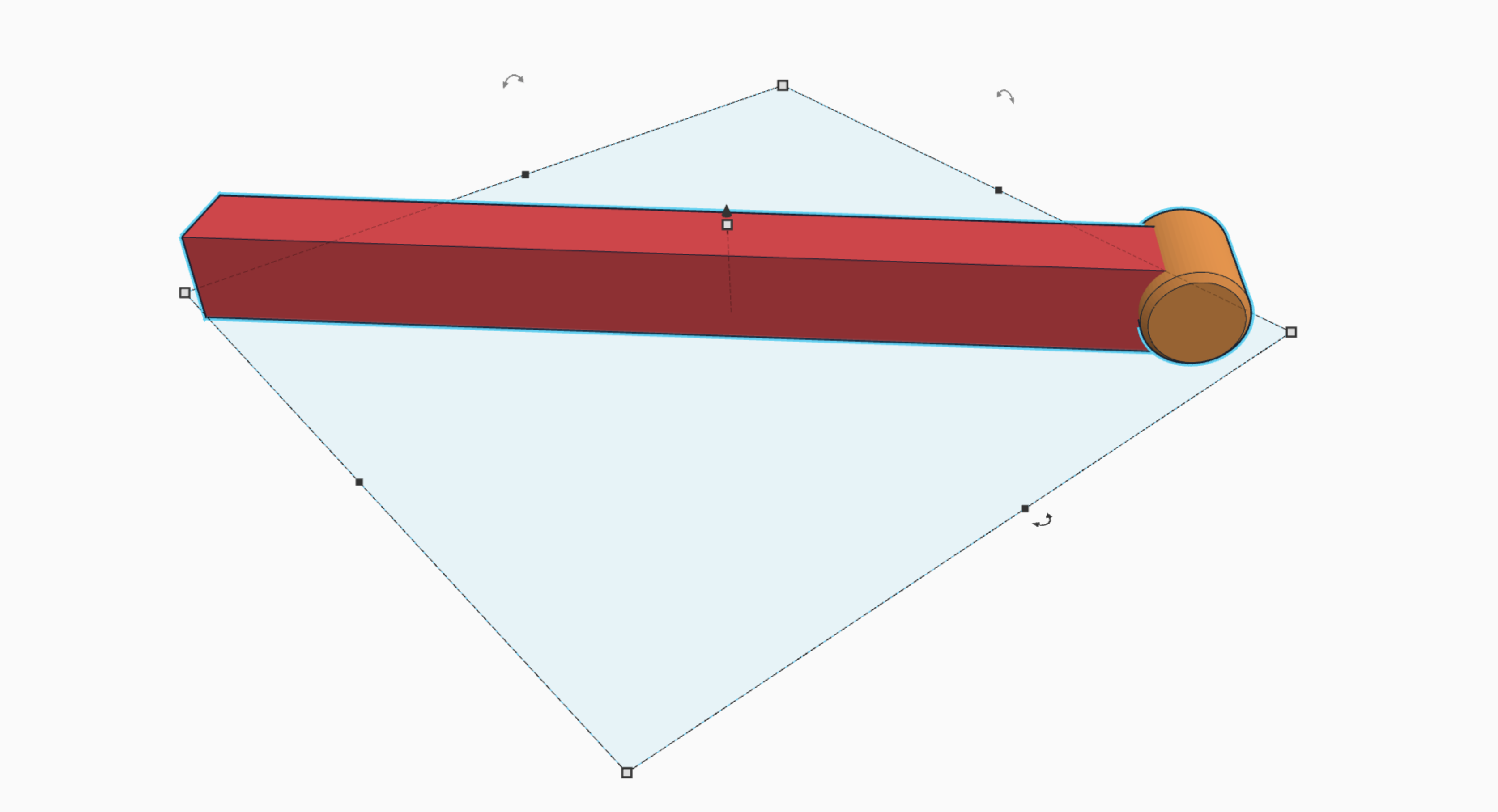
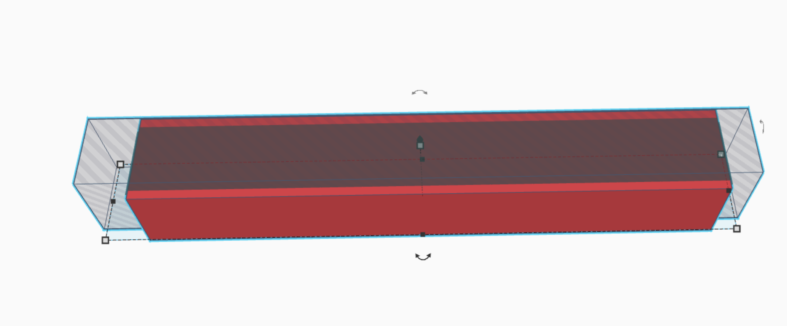
First, take a cube, and cut out a hole the same size as the arm from the previous step. (picture 2)
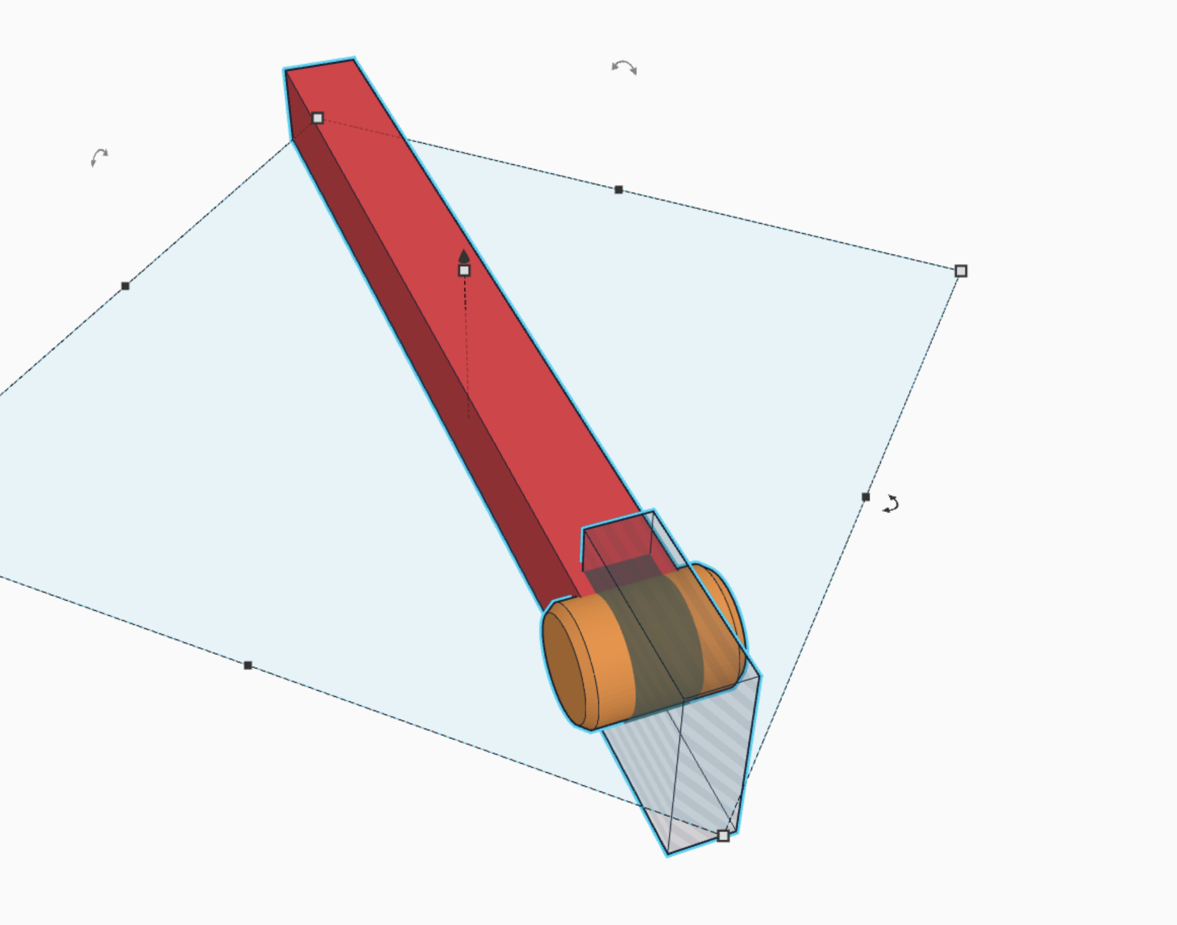
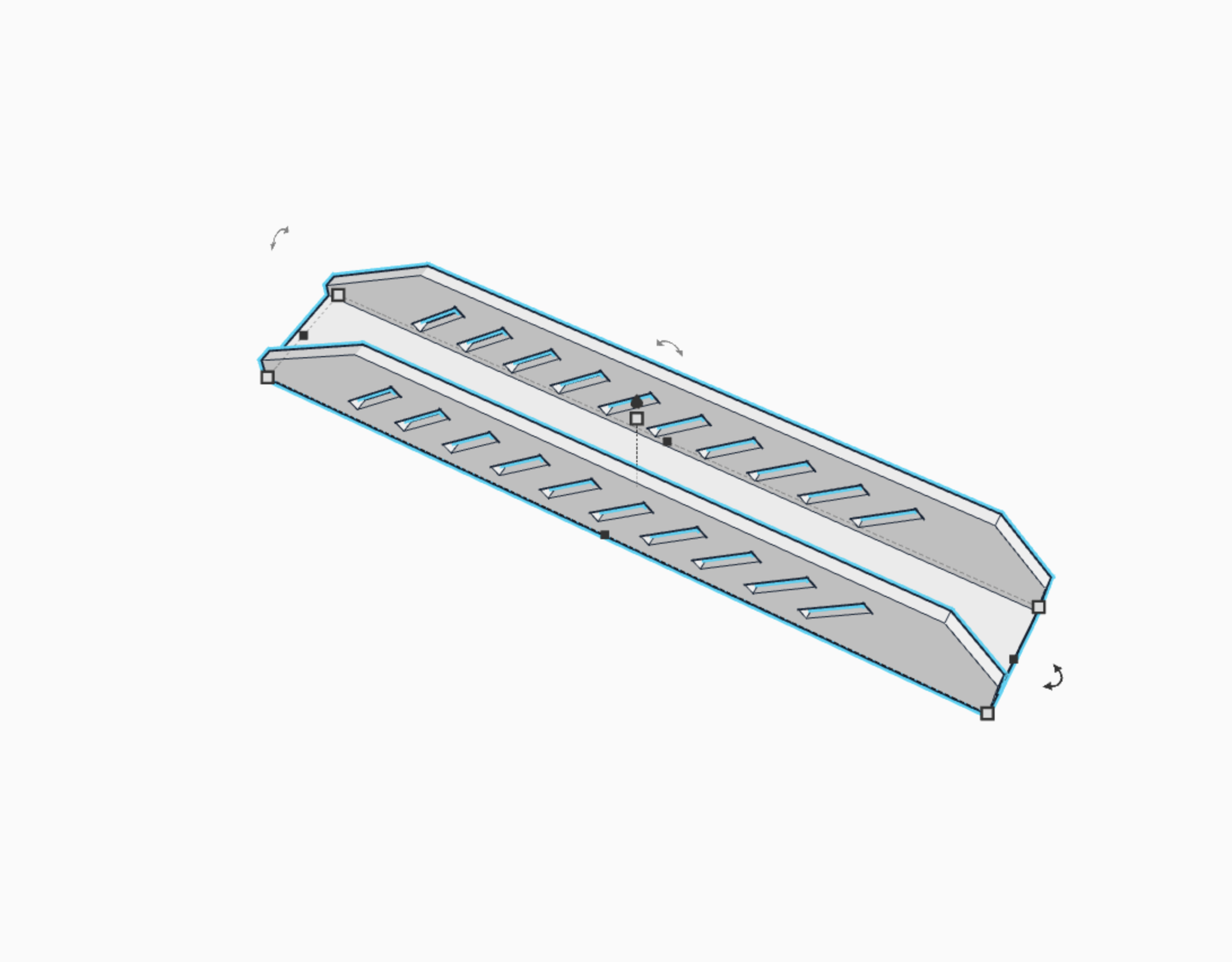
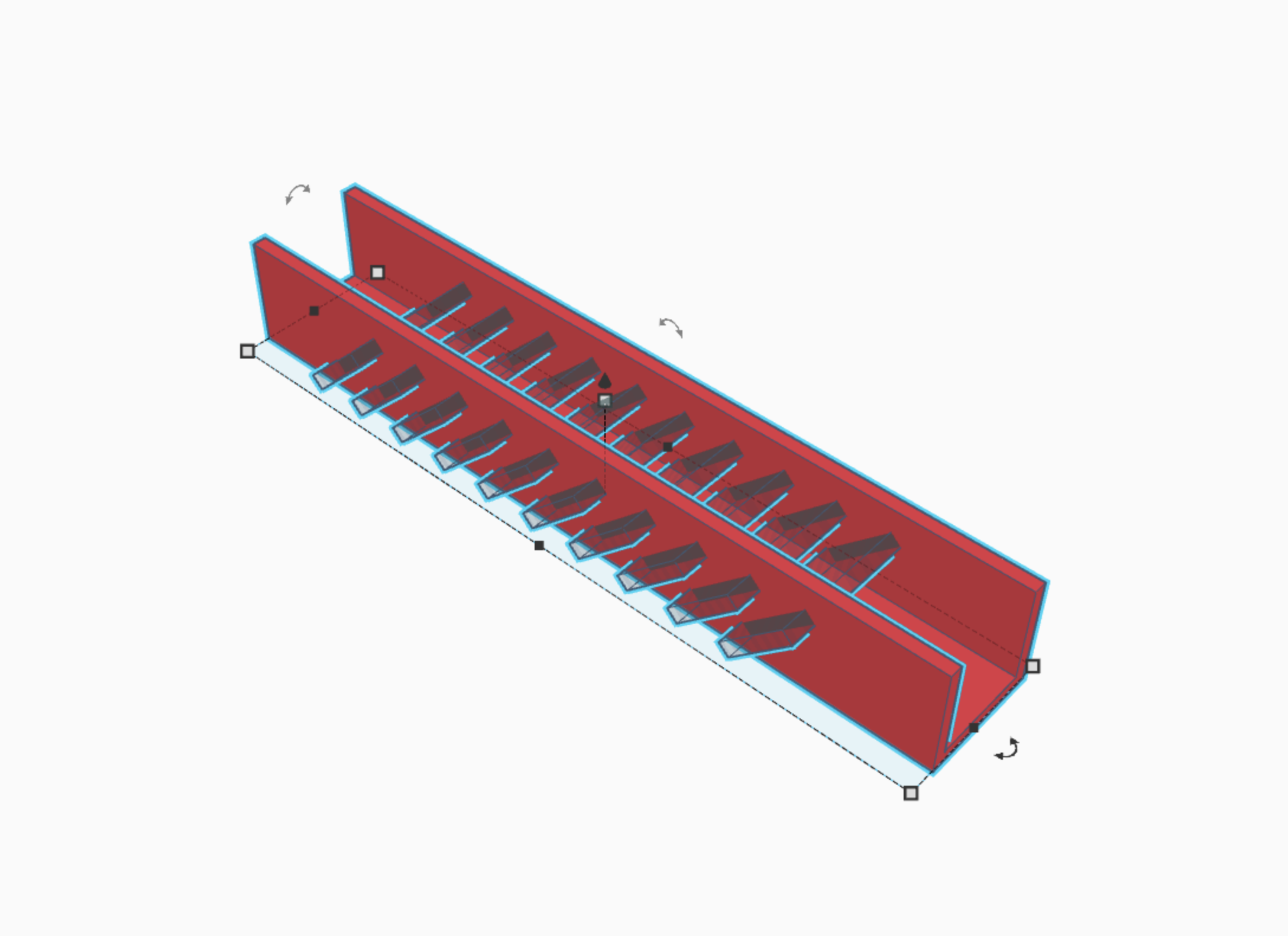
Second, take smaller cubes, rotate them 45 degrees and make them look like rectangles, before duplicating them along the entire length of the original cube. then group. This creates a ridged effect that looks kinda cool when finished :) (picture 3)
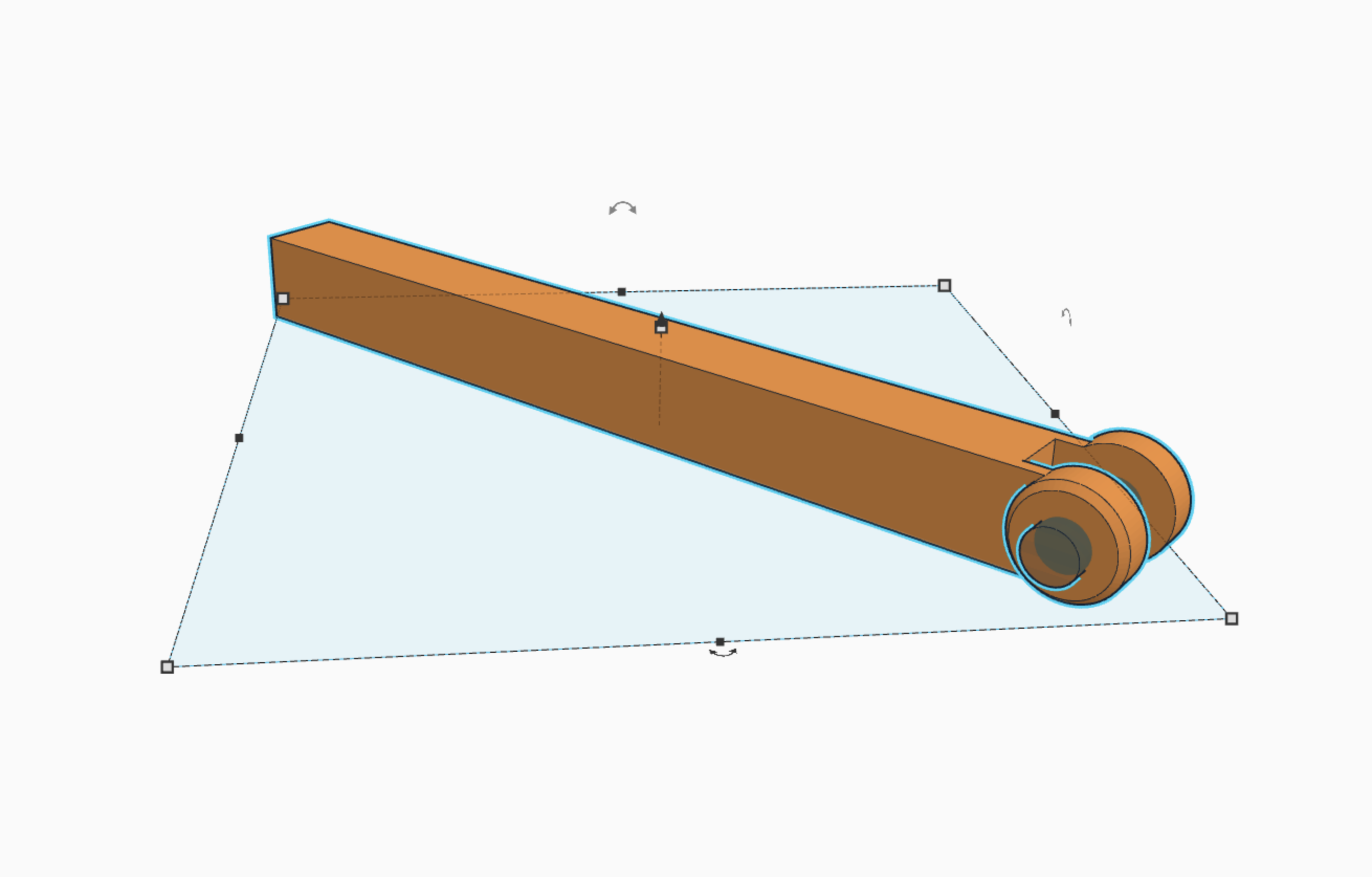
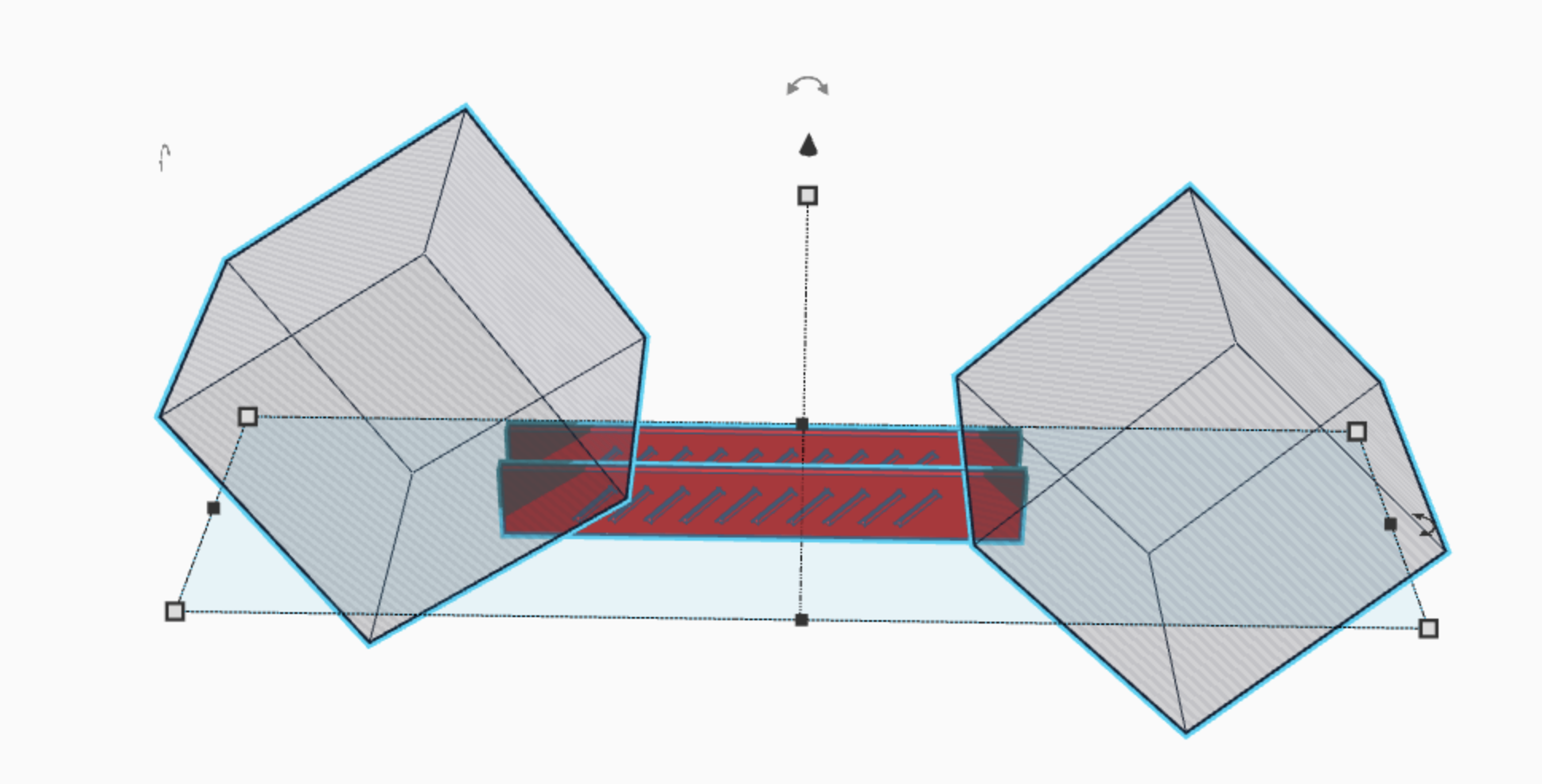
Third, take two cubes, rotate them at 45 degree angles and use them to cut off the edges of the original cube. (picture 4)
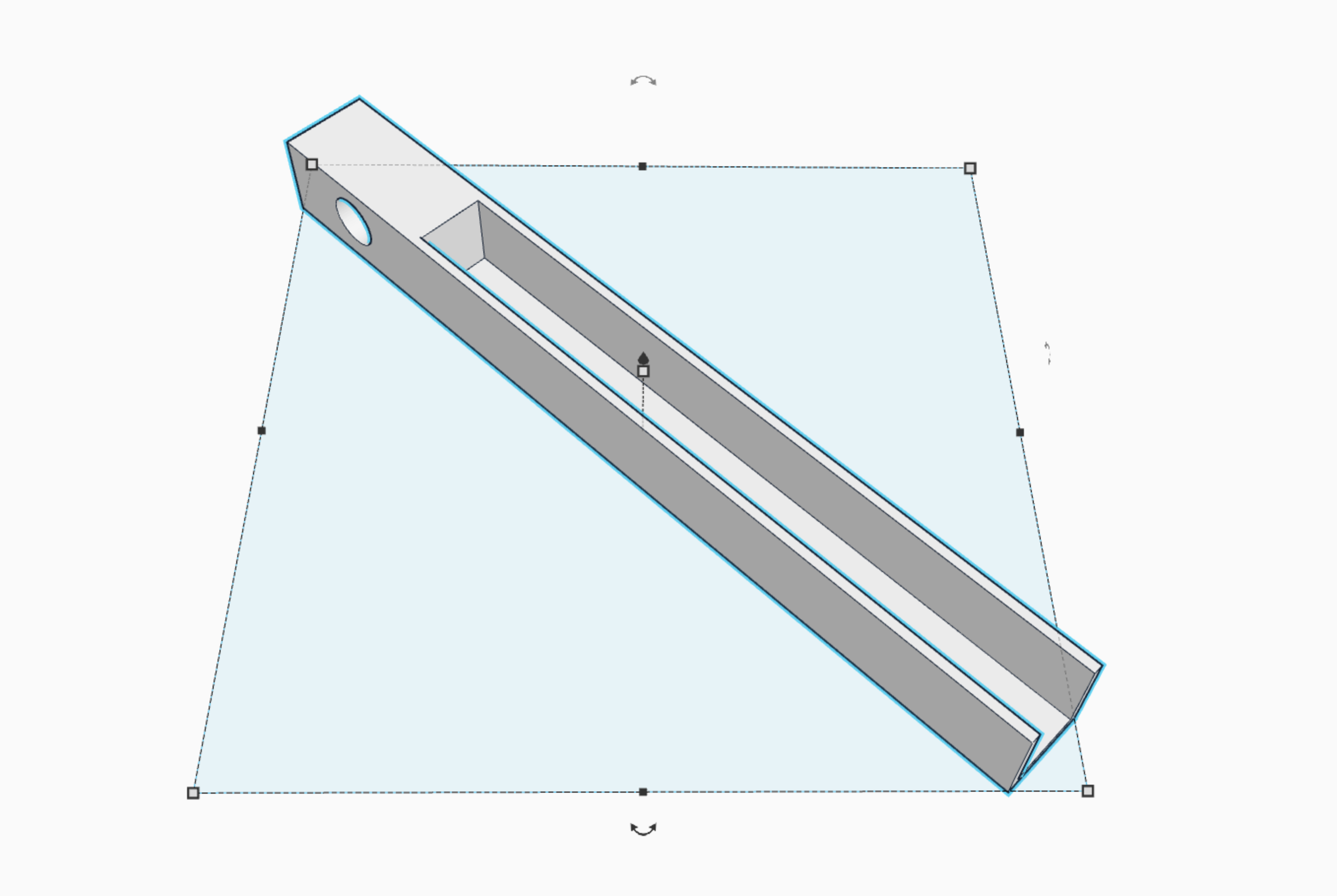
ALL DONE! :)
Wheel
There are four wheels to this machine, but you can print the same wheel four times as they are all identical. :)
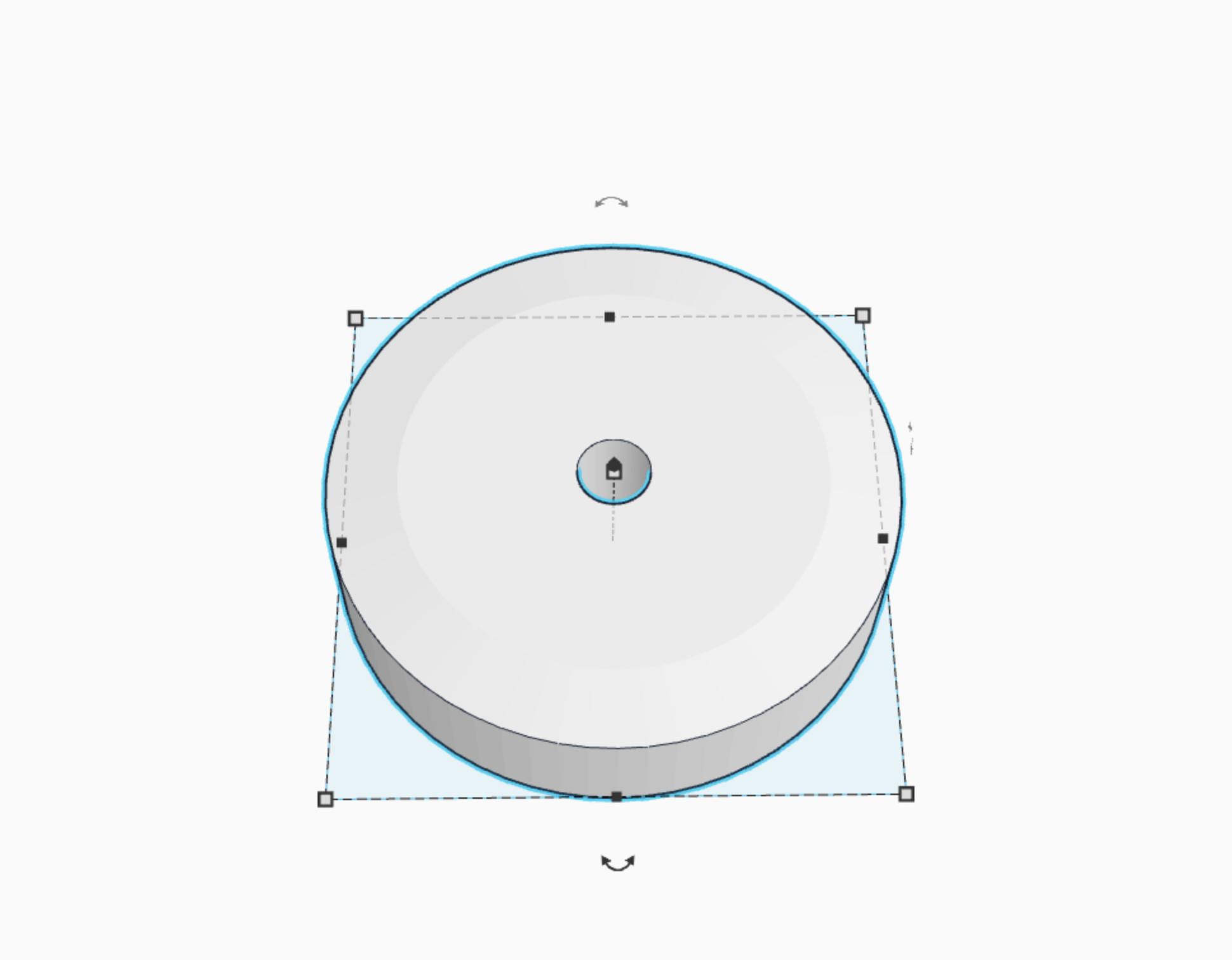
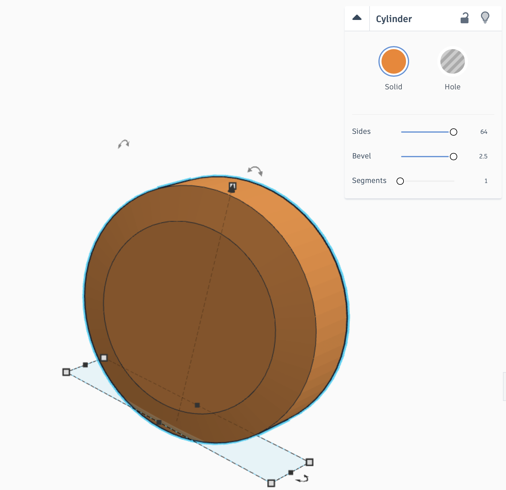
First, take a cylinder and set bevel to 2.5 and maximize the amount of sides. (picture 2)
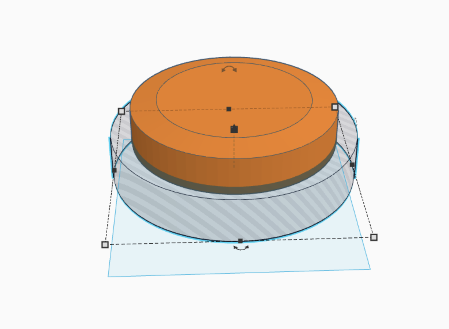
Second, take that same cylinder, and cut off the bottom so that only one side is beveled. (picture 3)
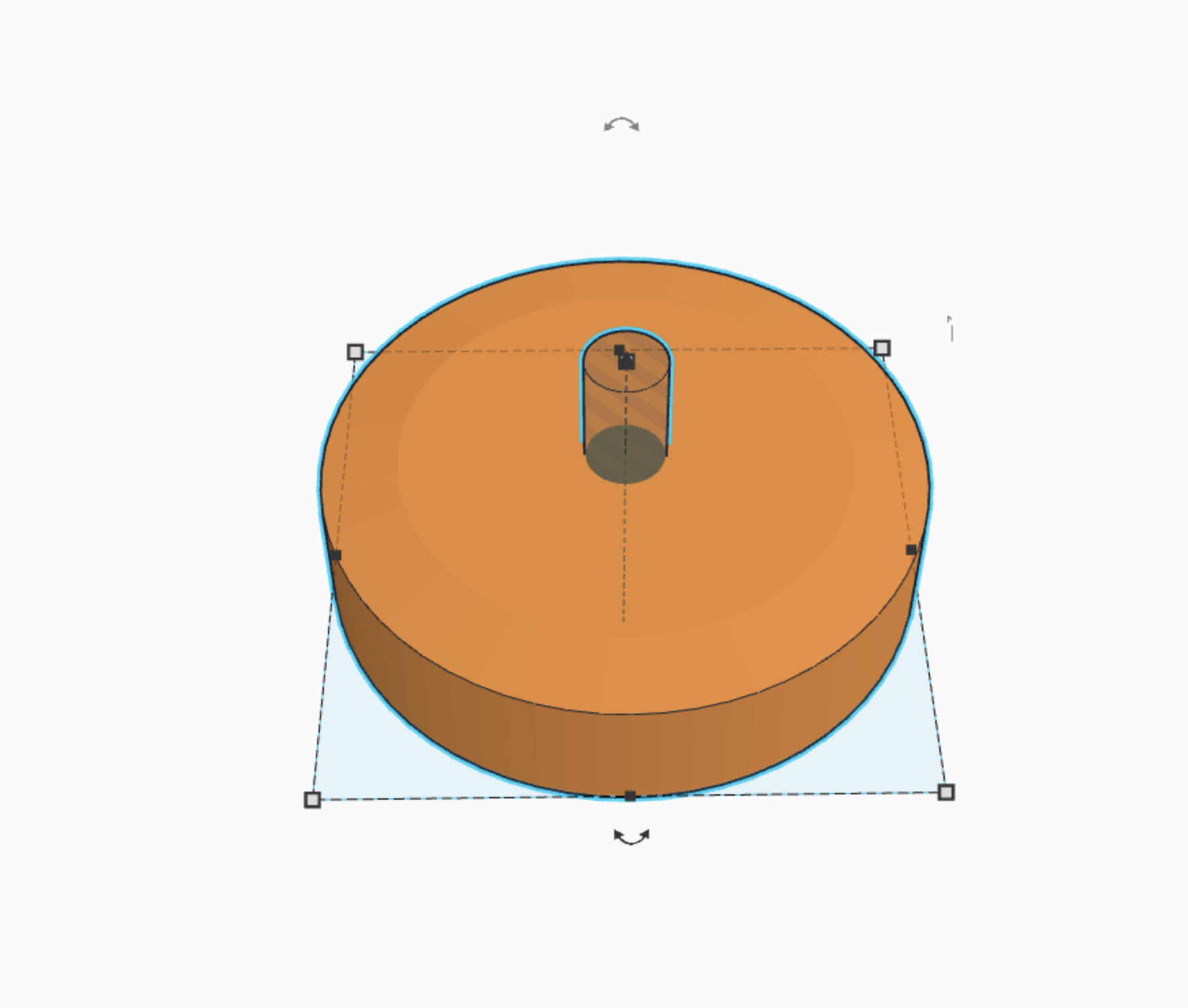
Third, take a smaller cylinder, and cut a hole in the middle of the original cylinder to create a place for the bolt to go through. (picture 4)
There you go! a complete wheel!
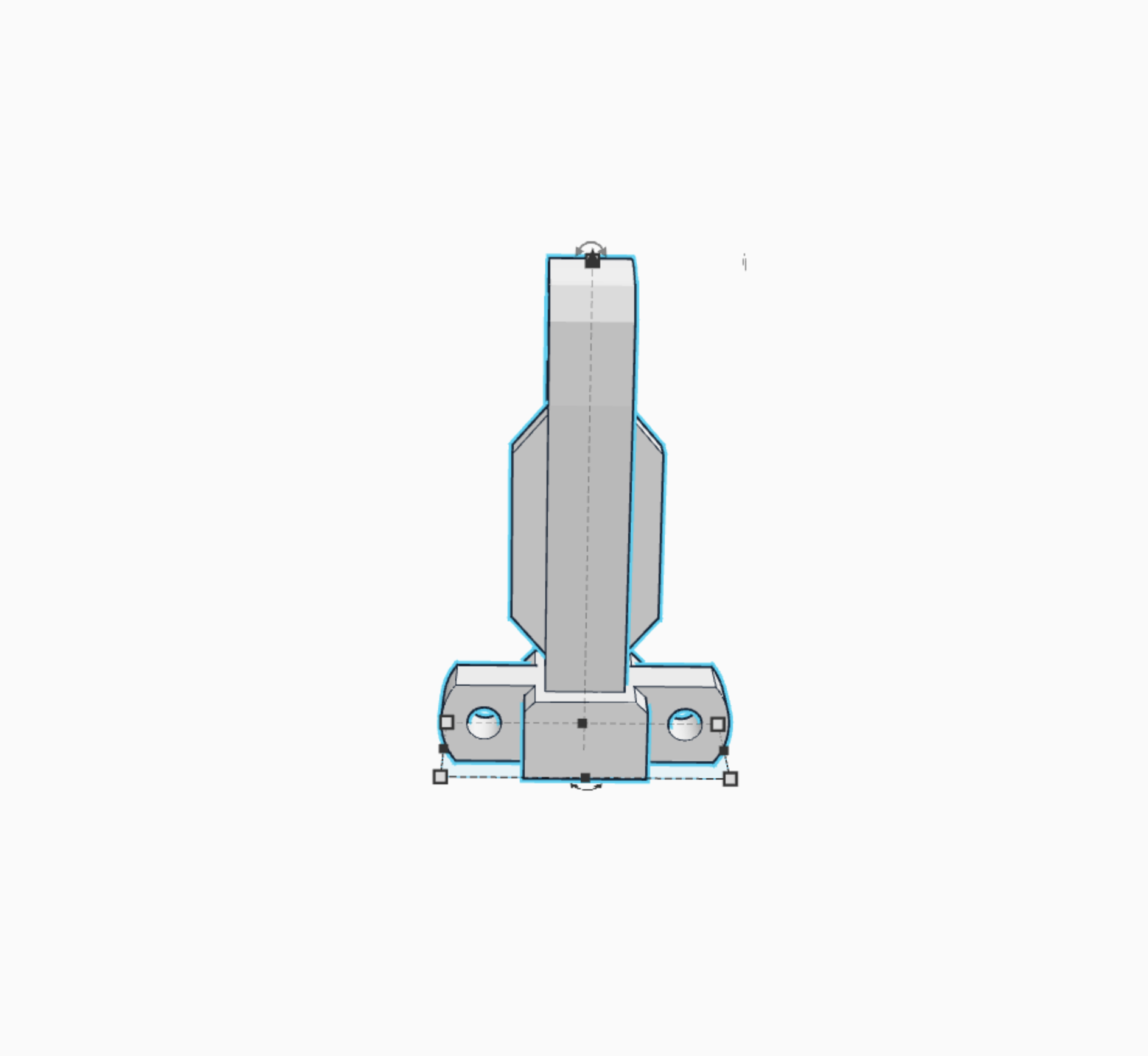
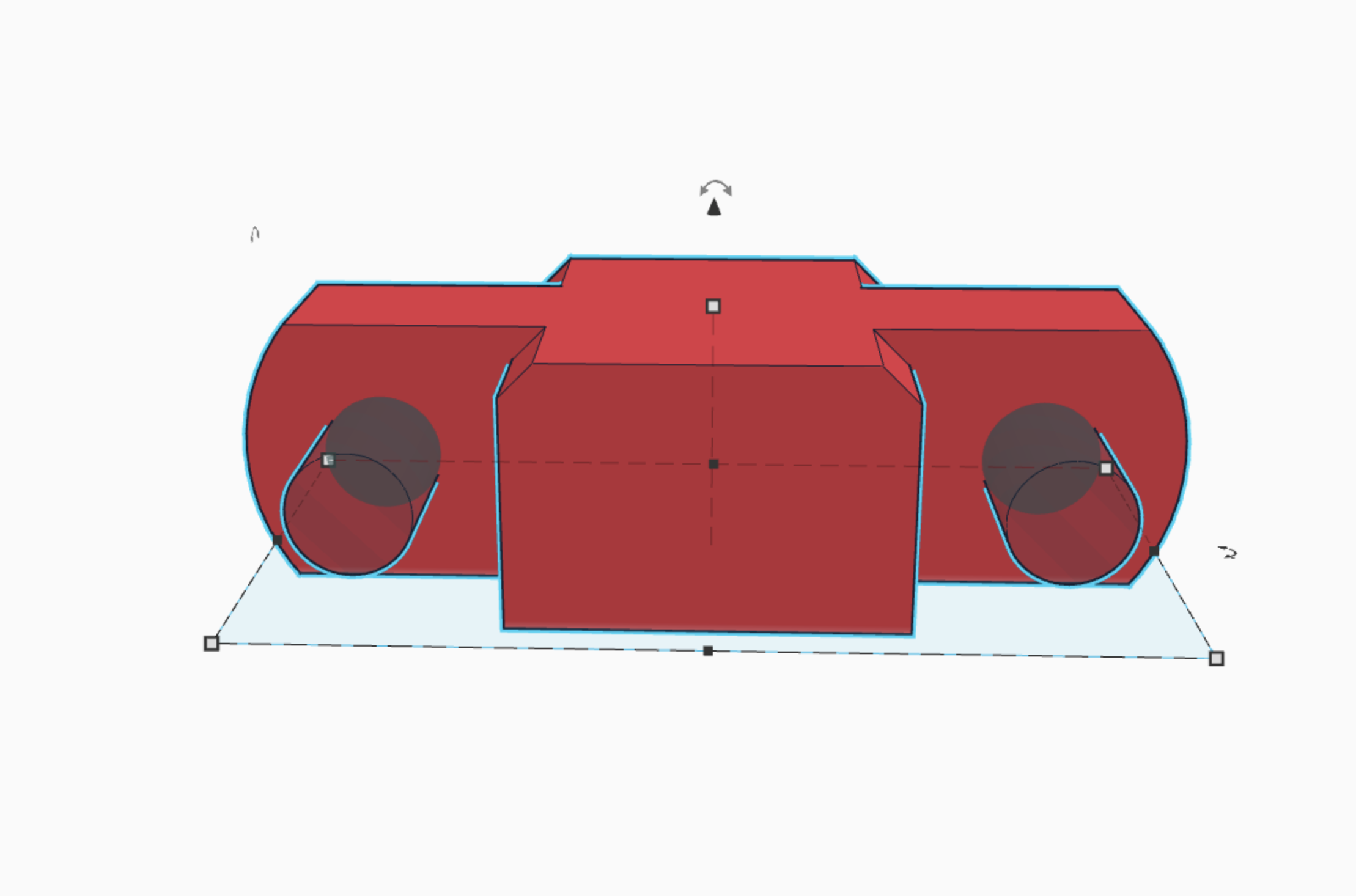
Bracket for the Wheels
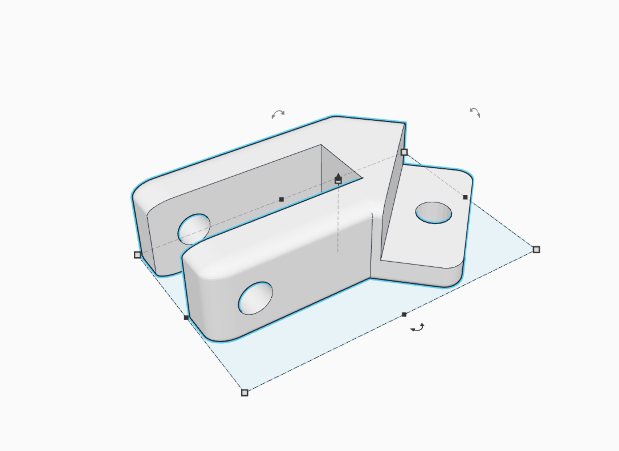
This is the bracket that holds the wheels to the frame.
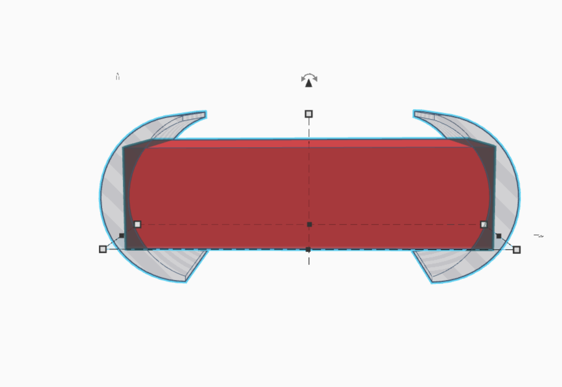
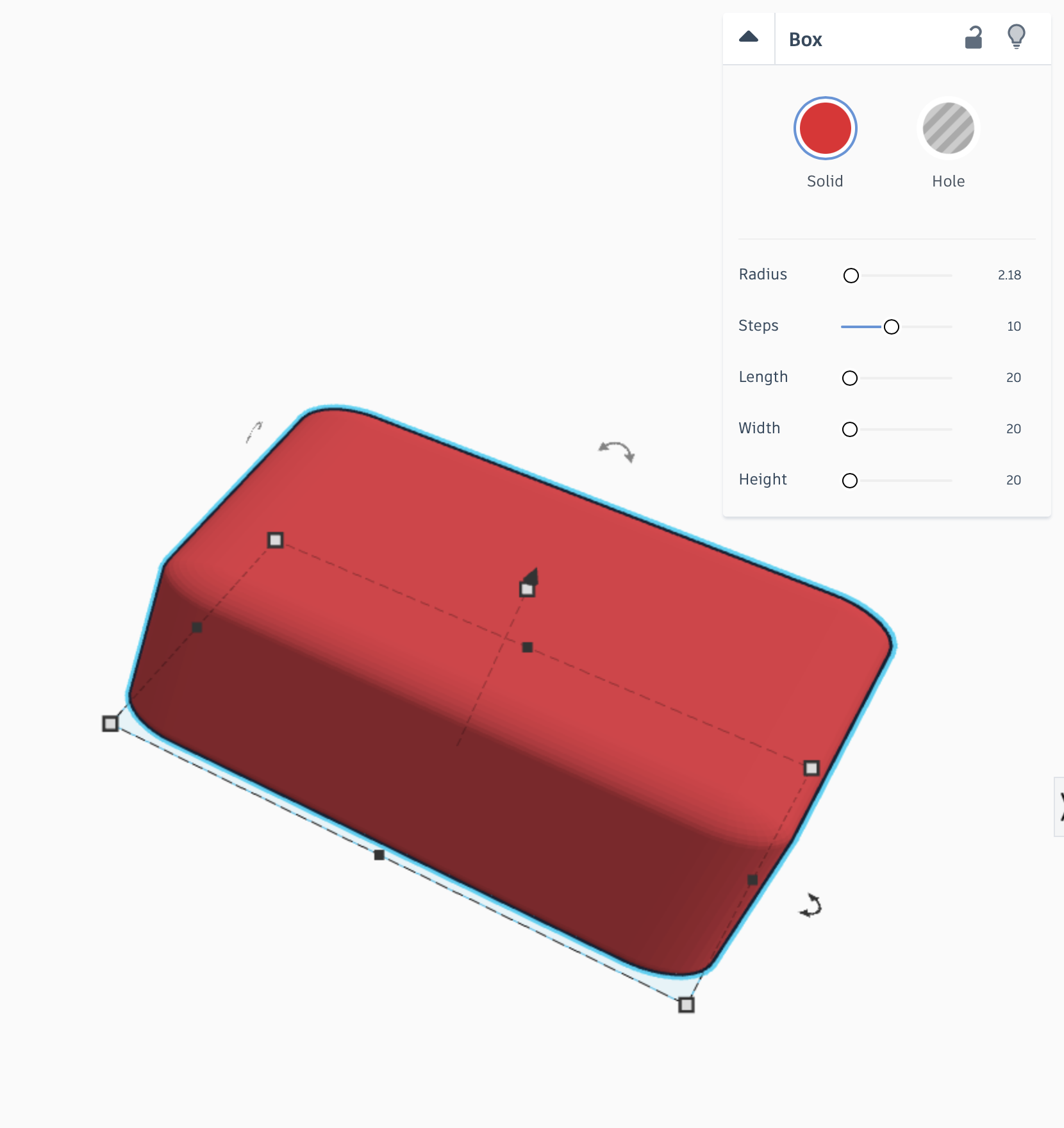
First, take a cube and set the radius to 2.18 and the steps to 10. this will round out the cube a little bit. also make it a little bit longer than a standard cube. (picture 2)
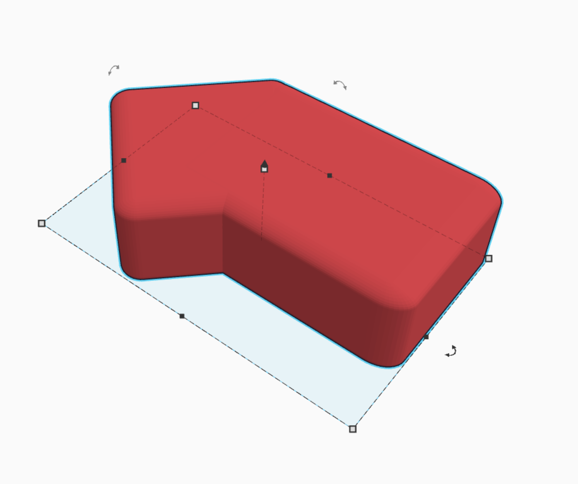
Second, duplicate the original cube, and rotate it 45 degrees. also shorten it a little bit first. then group both the original cube and the one you just created. (picture 3)
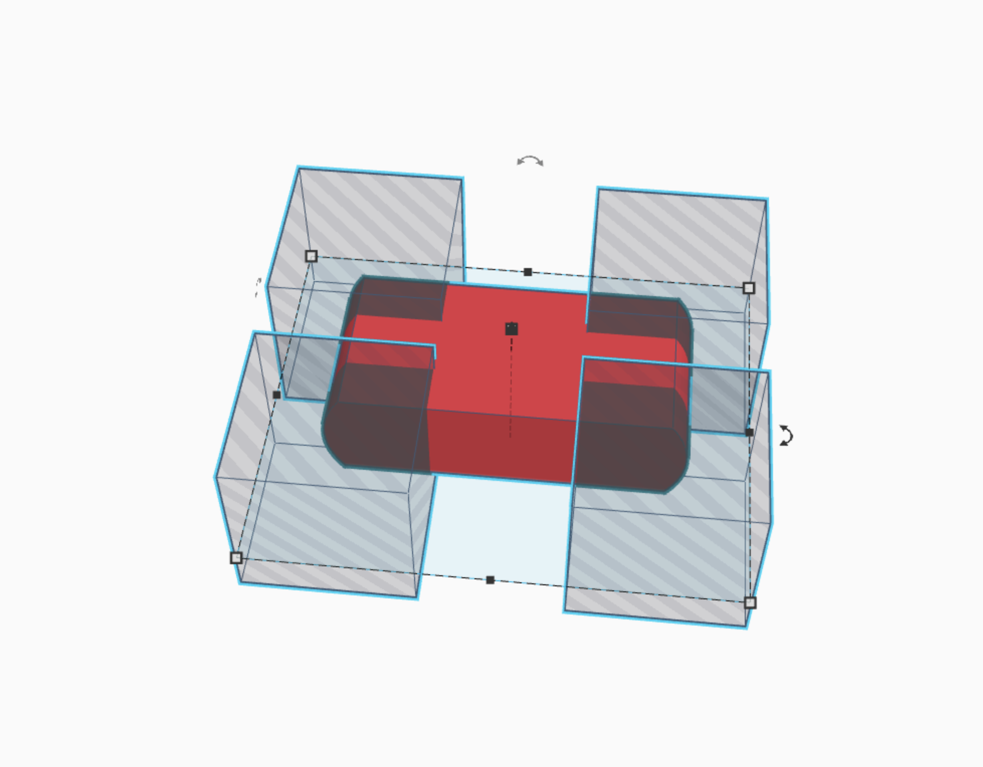
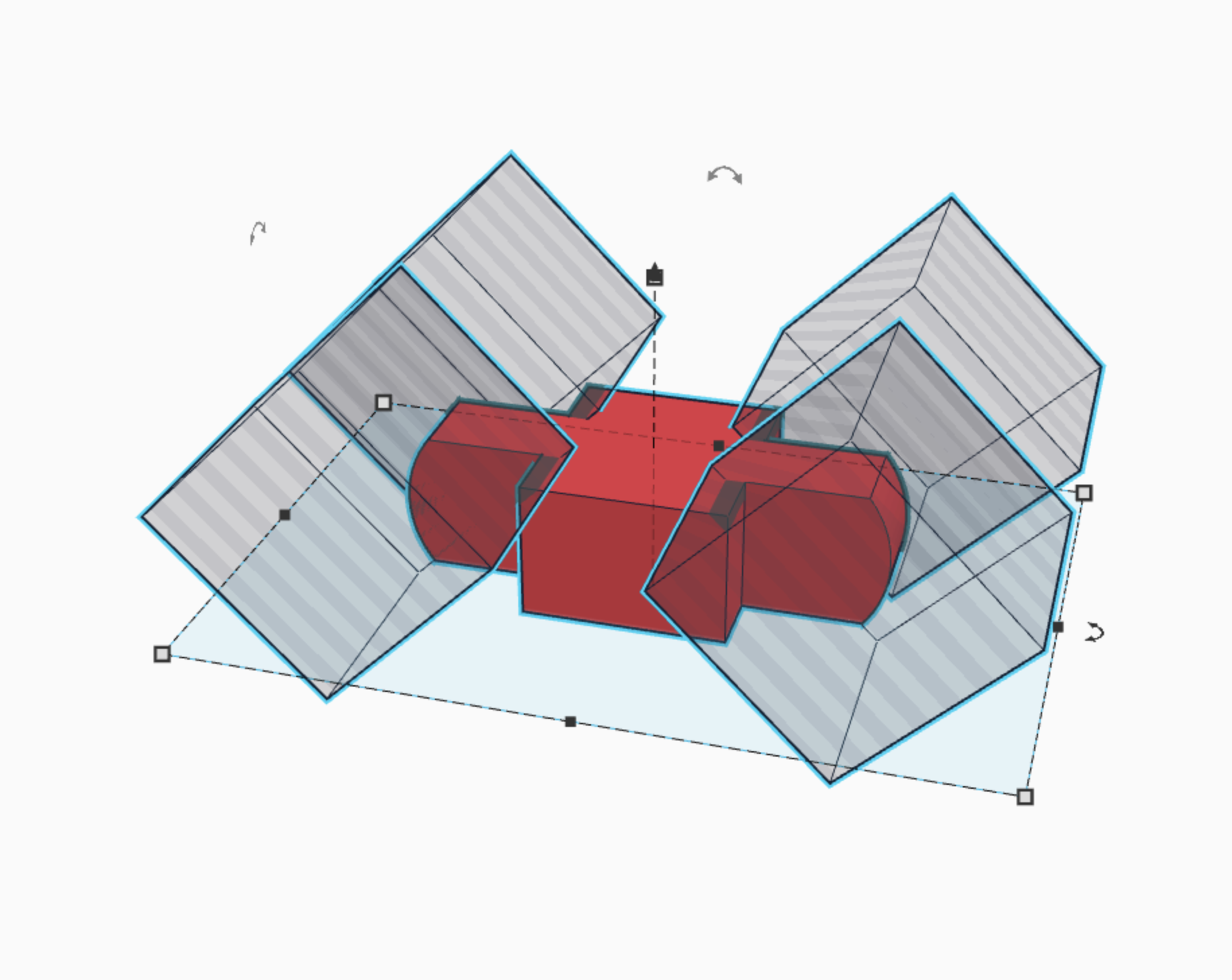
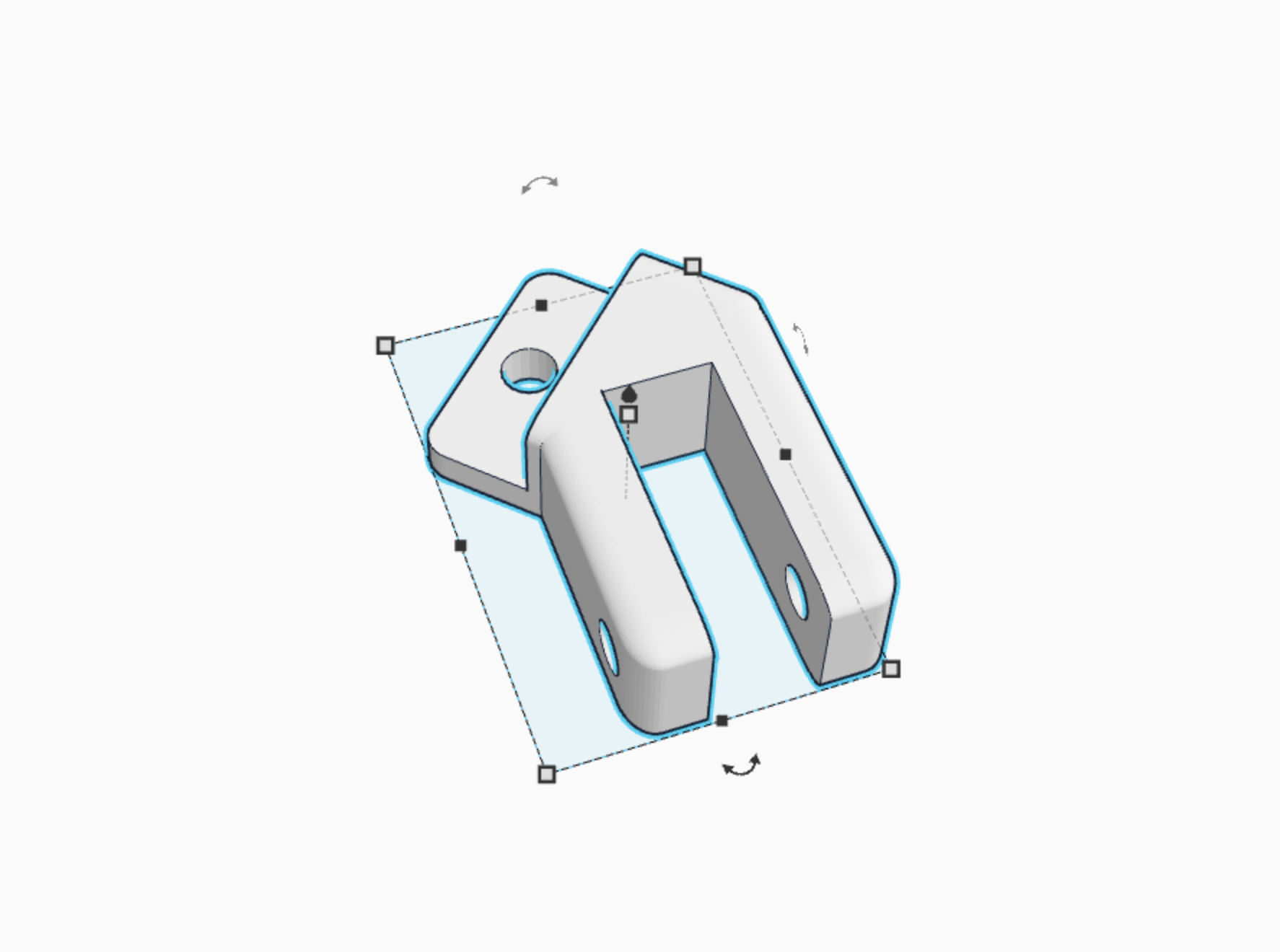
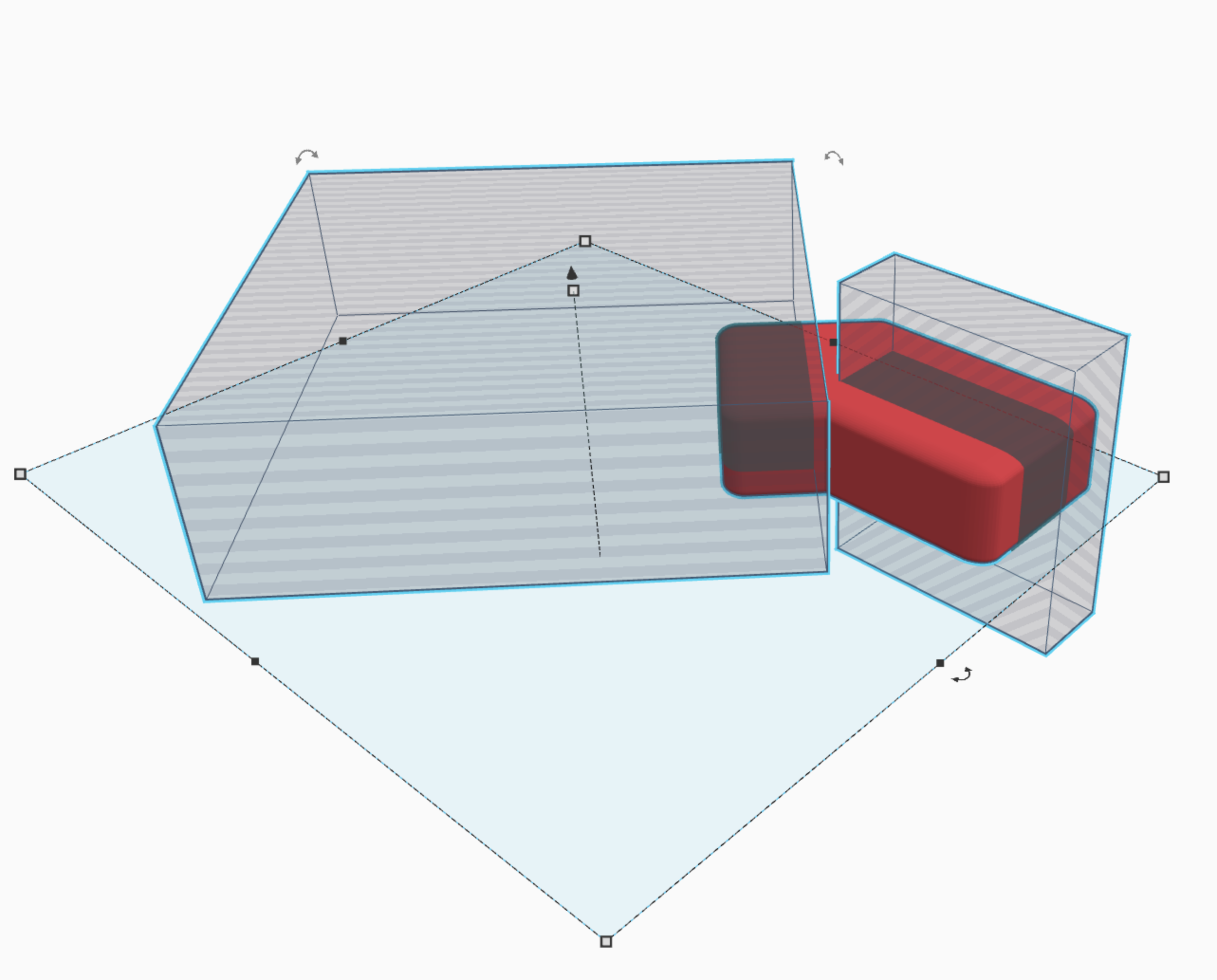
Third, take two cubes, and use the first one to cut off 3/5 of the second cube you just created. use the second one to cut out an area for the wheels. Make sure it is the same size as the wheels so that they will fit! (picture 4)
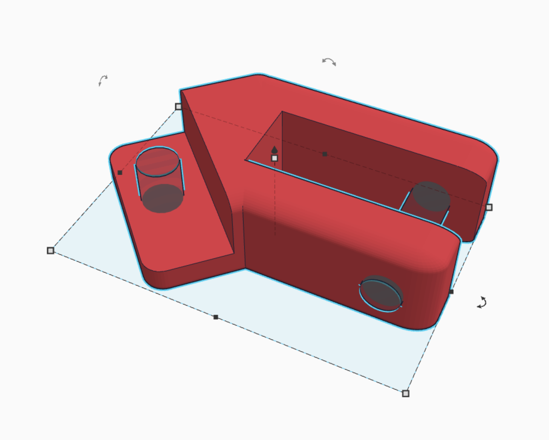
Fourth, take two cylinders, and cut holes for the bolts into the original cube. The first one is to attack the bracket to the main body. The second one is to attach the wheels, so make sure this cylinder is the same size as the cylinder you used to hollow out the wheel. :) (picture 5)
Fifth, hit m, and then flip the shape along the y axis, making a duplicate of the original shape, just opposite. This will allow you to make two brackets, one for each side. (you can reuse the same brackets a second time for the back wheels, but remember to flip them, as one bracket will not work on all four wheels.)
there you go! brackets :)
Base
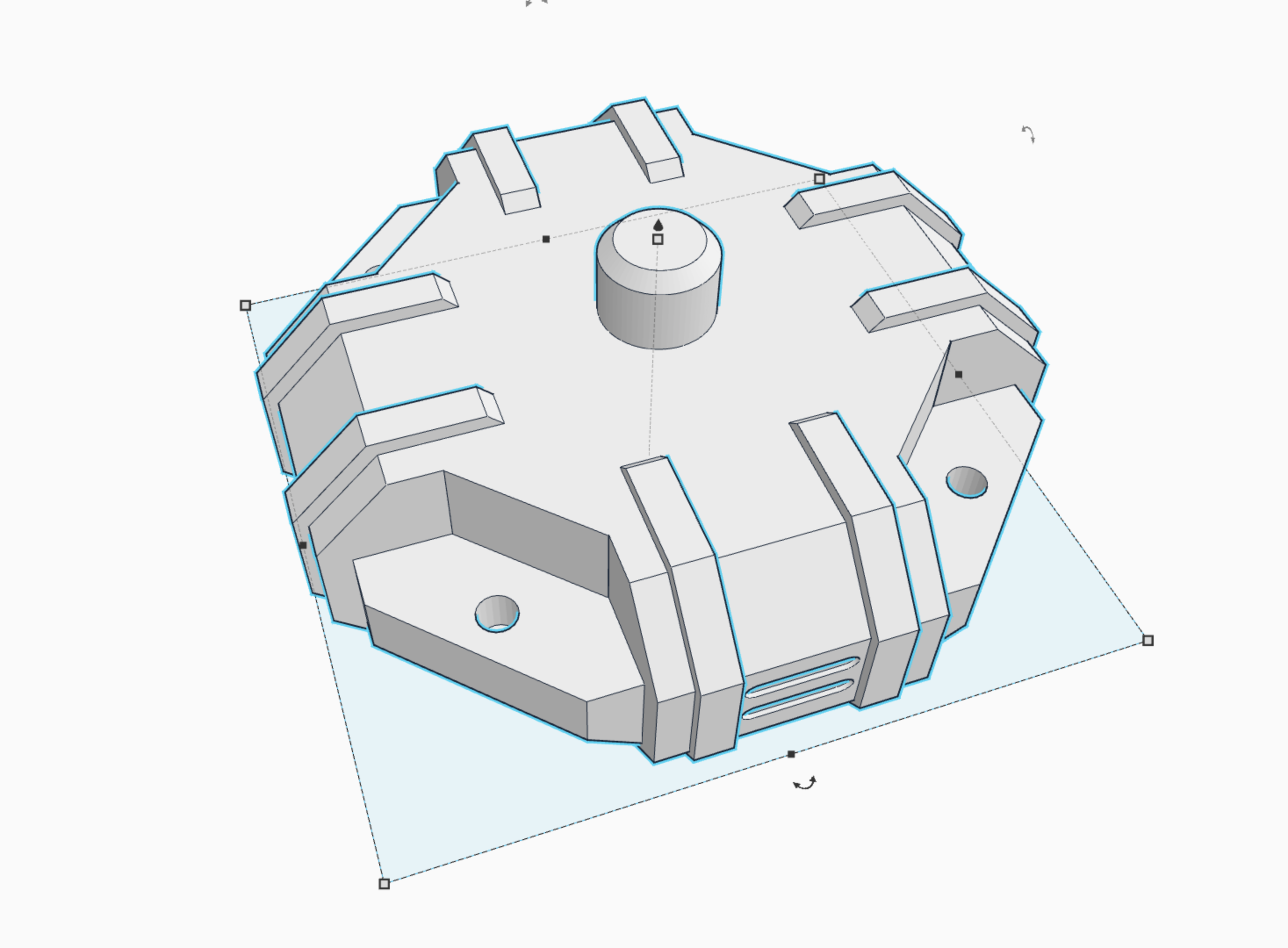
This is by far one of the more challenging pieces, but not quite as hard as the body. be prepared... :)
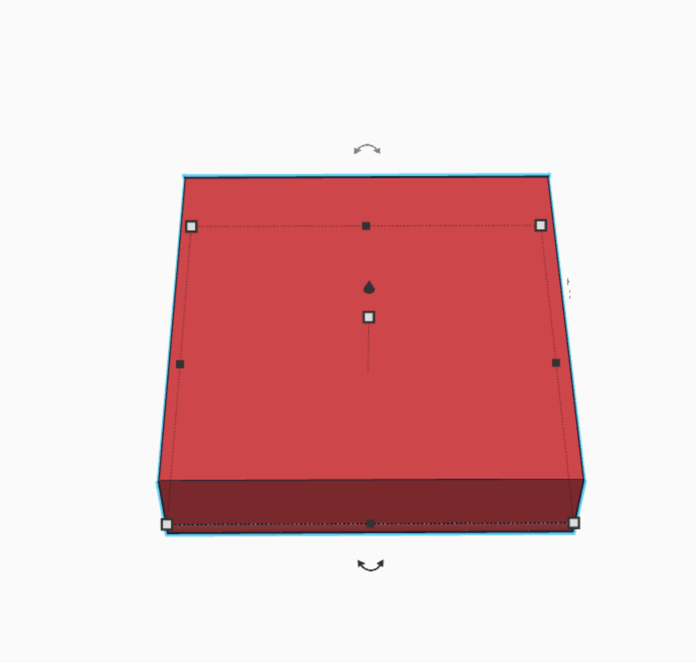
First, place a cube on the work plane, and make it only 1/3 its normal height. (picture 2)
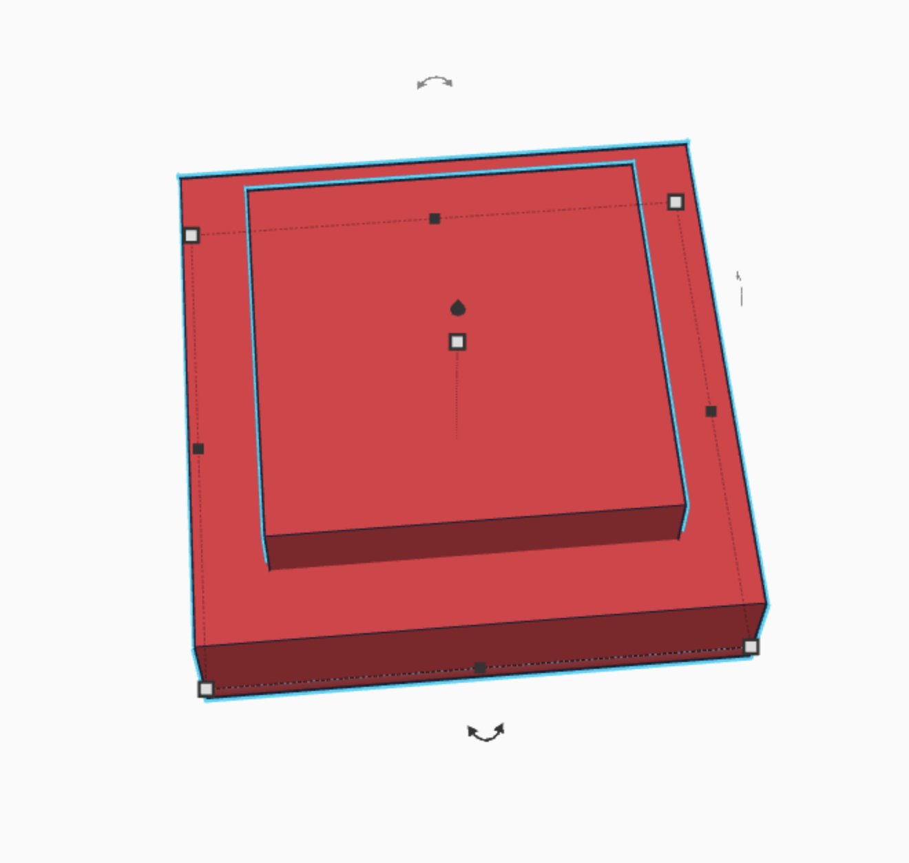
Second, make a second cube, the same height, but make it less long and wide. (picture 3)
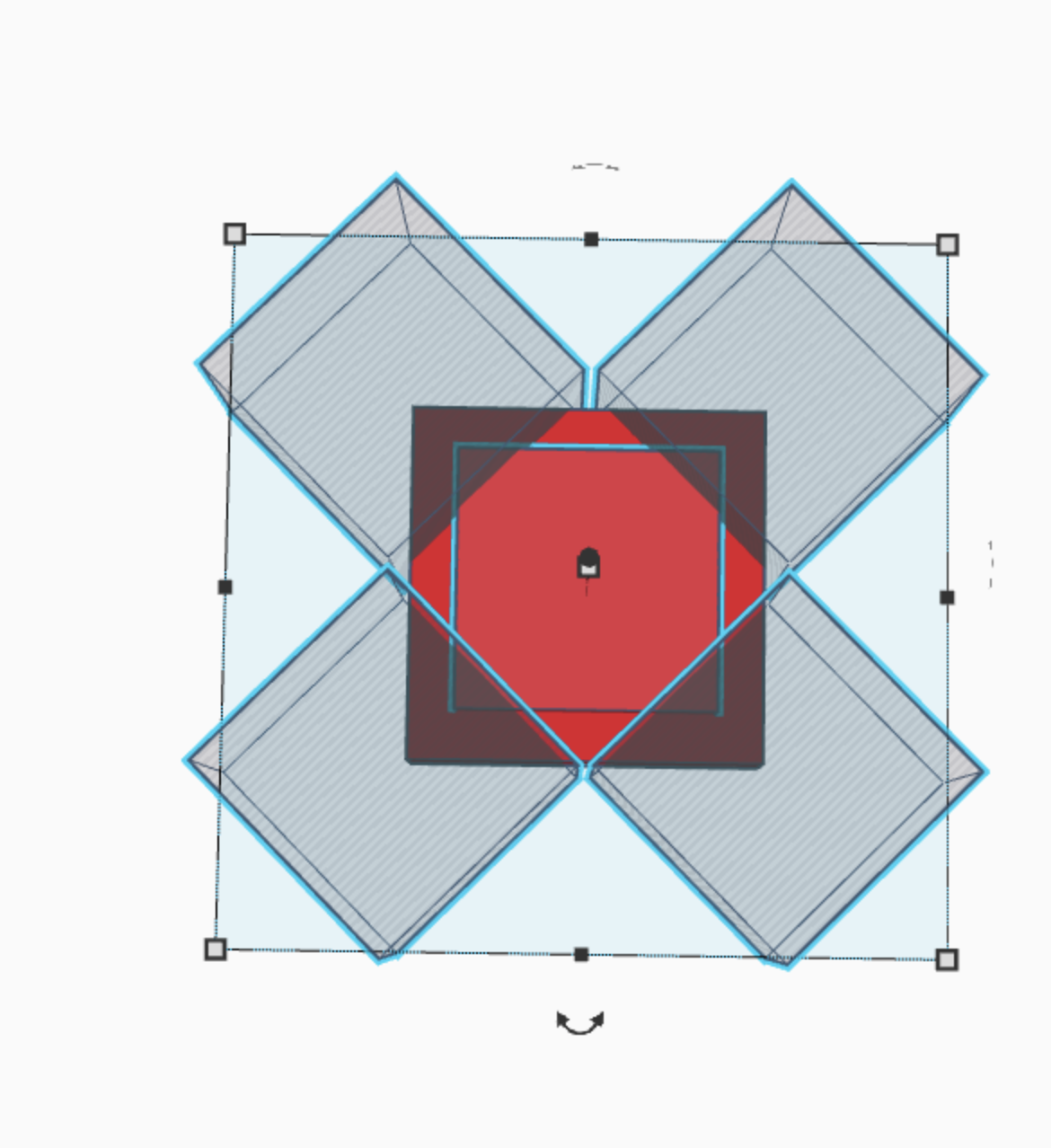
Third. Take four cubes, and rotate them 45 degrees. Put one in each corner of the top cube, and cut the edges off. Makes sure that the cubes are not touching and you leave 1/3 of the edge. (picture 4)
Fourth, repeat what you just did, but this time on the original cube. (picture 5)
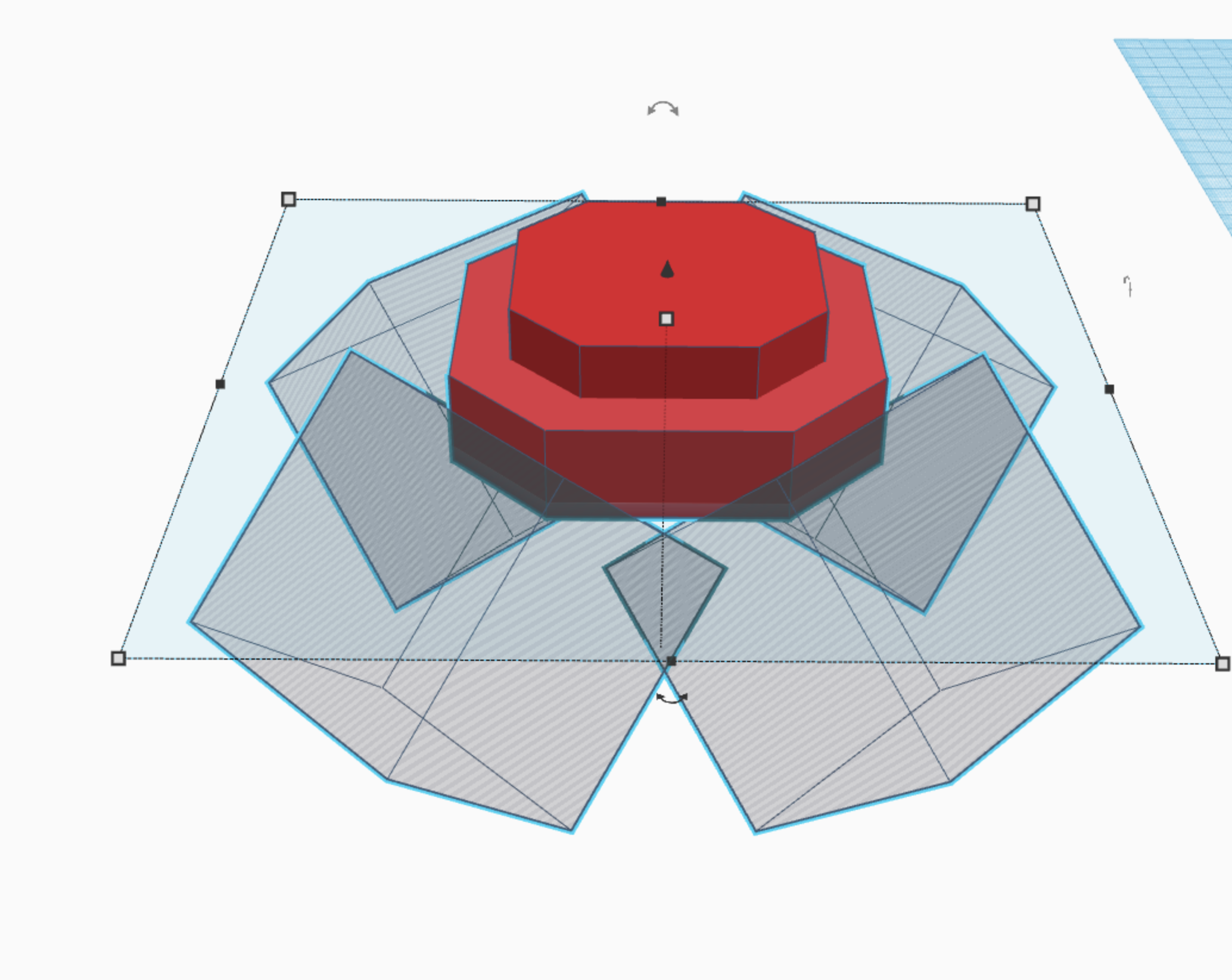
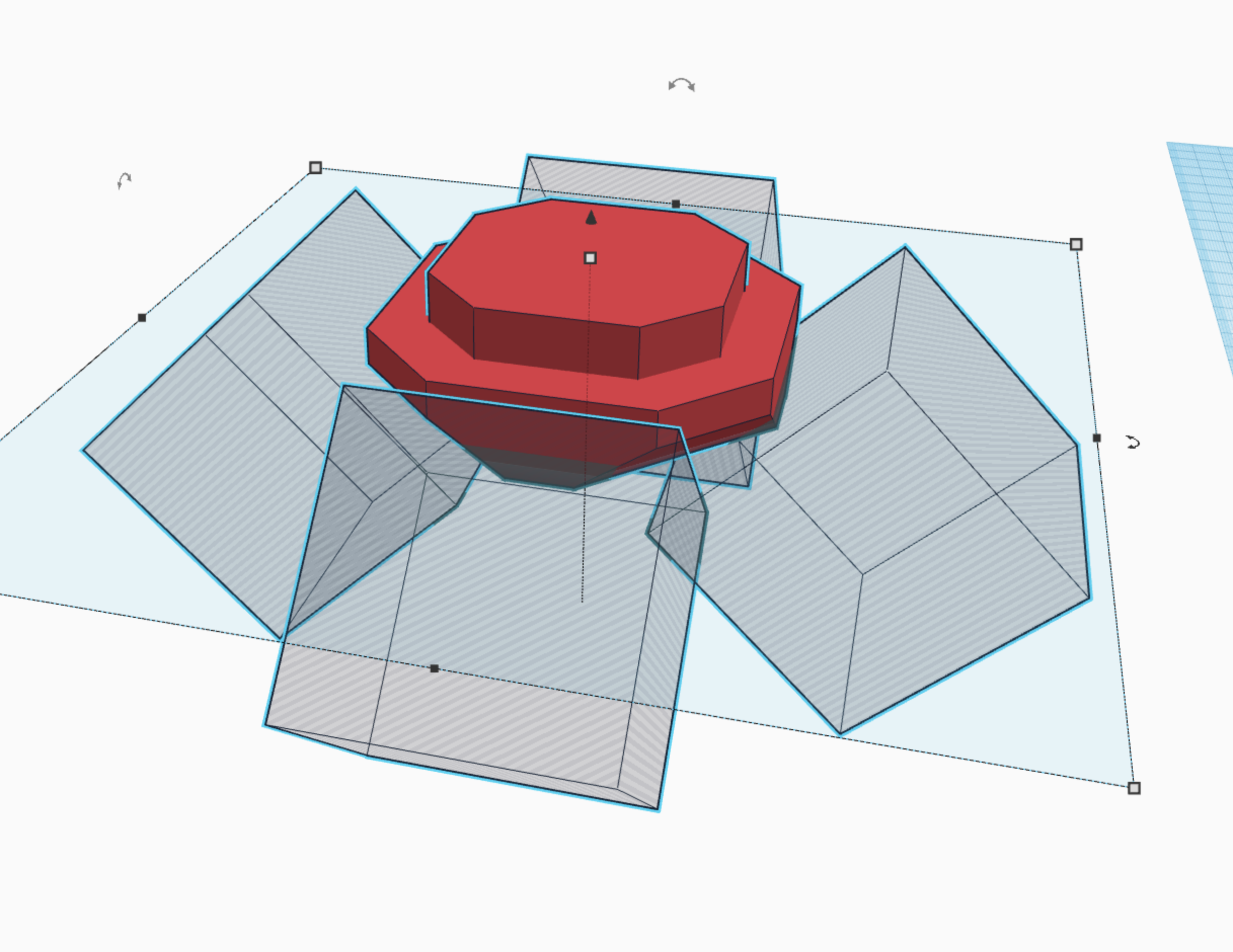
Fifth, do exactly what you did in the previous instruction, but rotate the cubes at 45 degree angles along the x, and y axis, so that it cuts the bottom at an angle. (picture 6)
Sixth, repeat the fifth step, except the cubes need to be rotate 45 degrees along the z axis, so that it cuts the whole bottom at an angle. (picture 7)
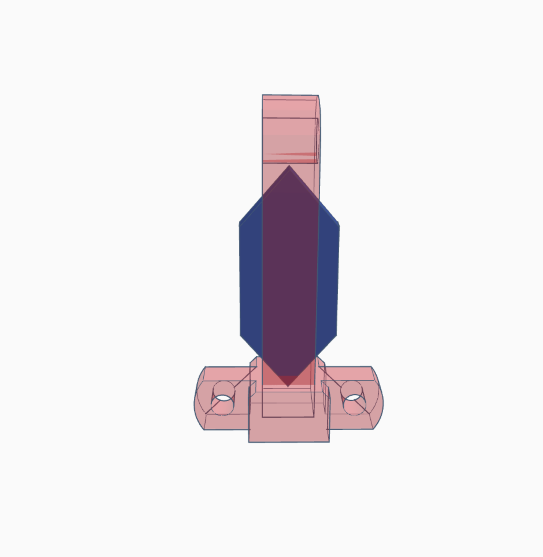
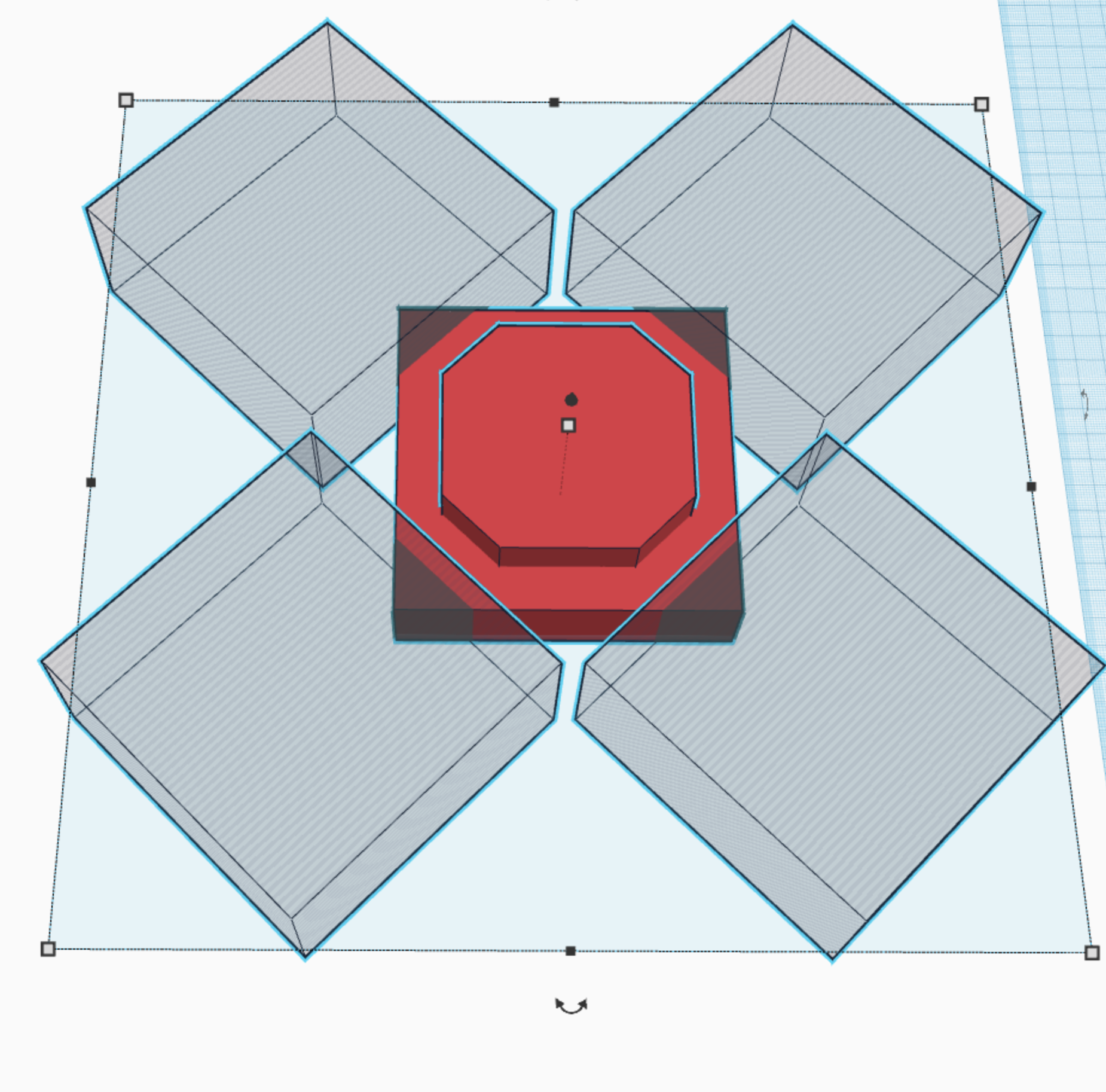
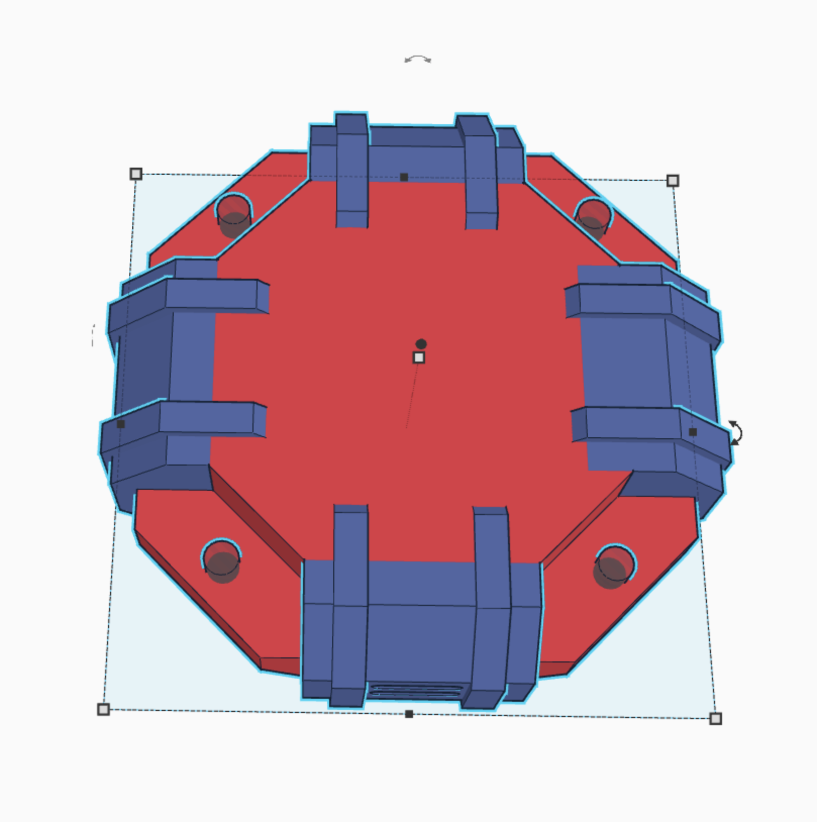
Seventh, take 4 octagons, and make them the same height as both the first and second cubes put together. Make the width the same as the width of the second cube (top cube) and make them halfway into the original cube. (picture 8)
Eighth, take a cube and cut just a small portion of the bottom off, so that it is completely even, and there are no overlapping rough edges. (picture 9)
Ninth, take a set of cylinders and place a cube in between them to get the hole shape. Make two of them and cut out the middle of each octagon. It provides a grid like look. (just decor, picture 10)
Tenth, take 8 more octagons, and make them just a little bit larger than the original octagons. Then shorten them so that they are 1/6 the width of the originals. set them on the bottom of the work plane just like the rest of the shapes, and then place them against the first octagons so that they form a ridge. (view picture 11)
Eleventh, take four cylinders, and make them into holes so that you can place a bolt through them and into the base. These cylinders MUST be the same size as the cylinders that cut the outside hole in the brackets. {see previous step} (picture 12)
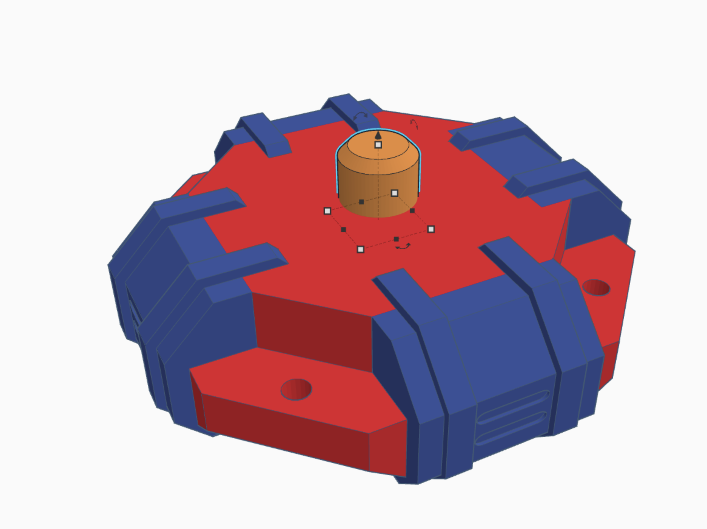
Twelfth, take a large cylinder and set the bevel and sides to maximum, and place it in the center of the base. (picture 13)
And there you go! you have a completed base! :)
Body
The body is definitely the hardest section of this toy to make. Not only is it very detailed and complex, but there are lots of shapes that must be made exactly right or it won't work.
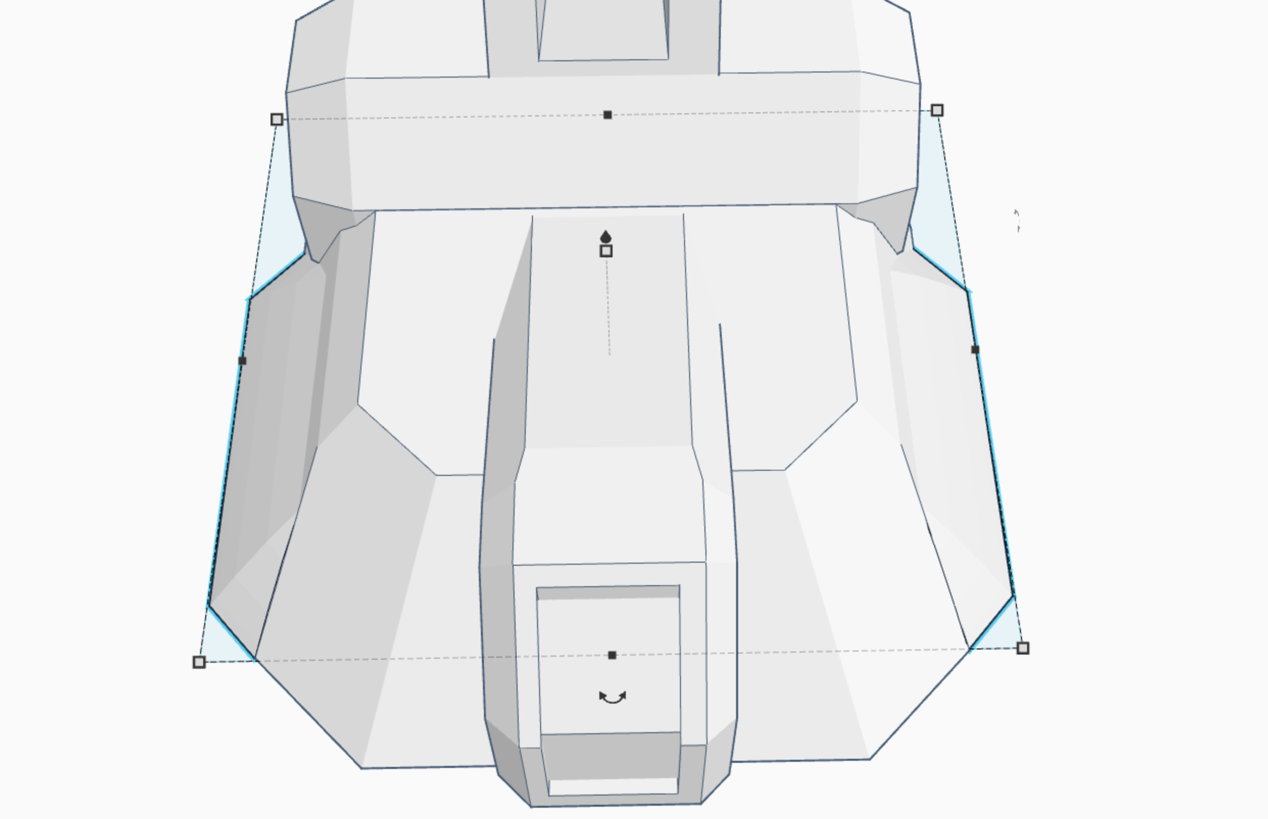
First, Like usual you are going to start with a cube. :) (picture 2)
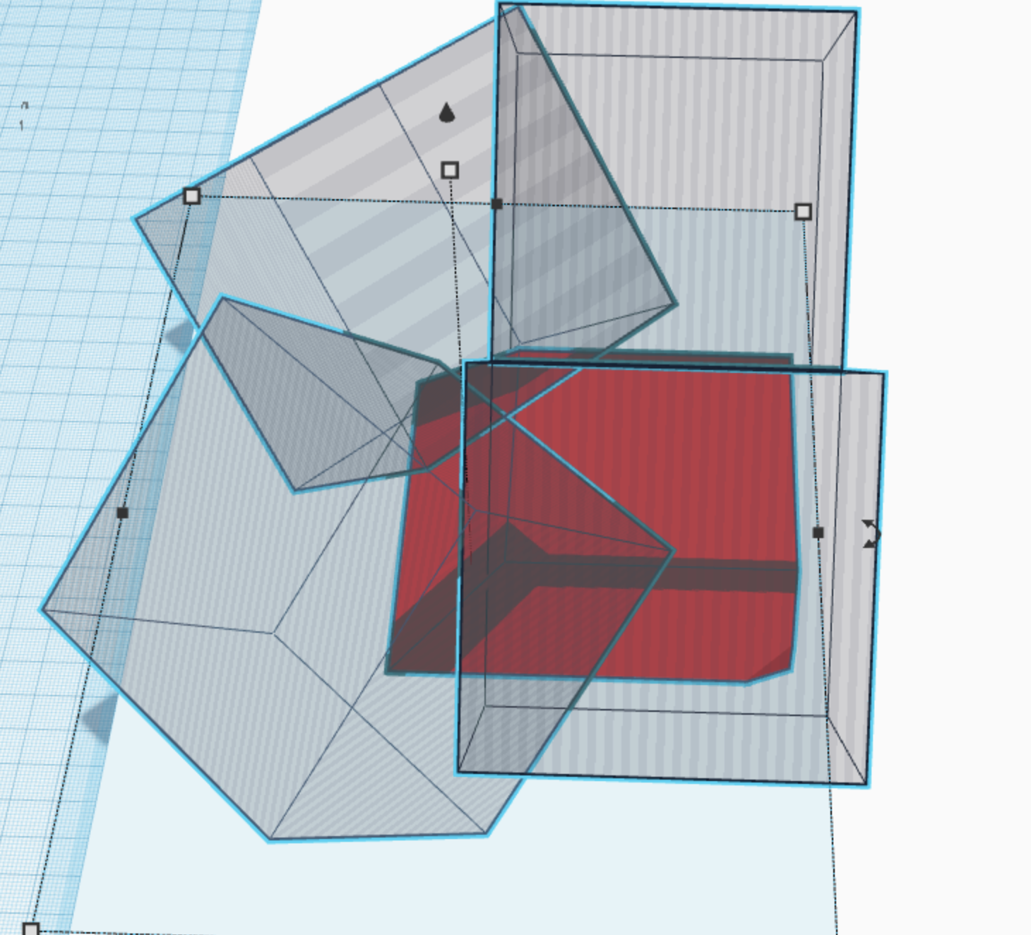
Second, cut the edge of the cube at a 45% angle by making another cube and rotating it 45%. (picture 3)
Third, cut both the right and left sides in exactly the same way. also cut off a tiny edge from both sides on the back. (picture 4)
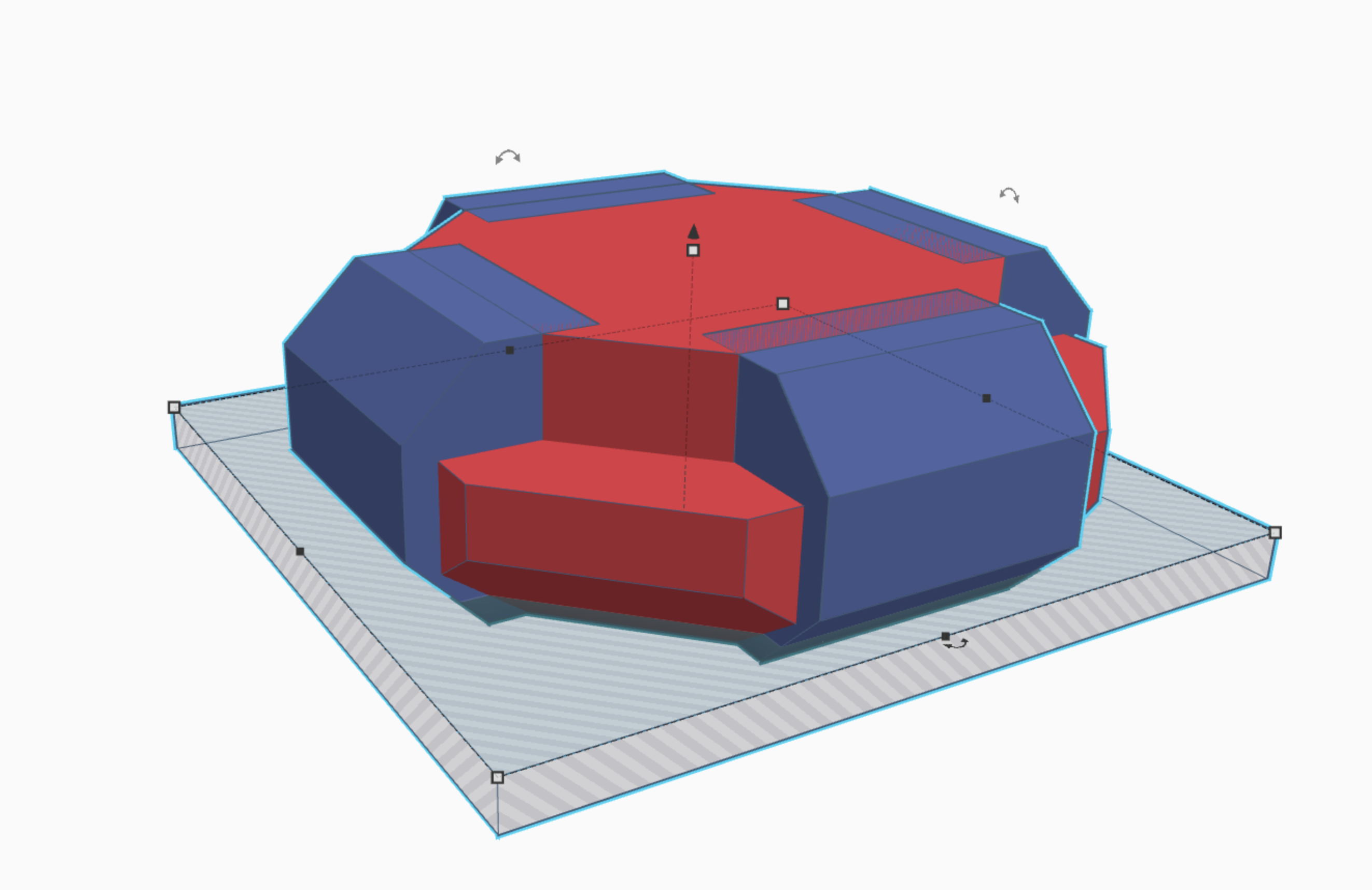
Fourth, bevel the edges of the original cube, by taking four cubes and rotating them at angles to cut off the sharp edges on top of the cube. (picture 5)
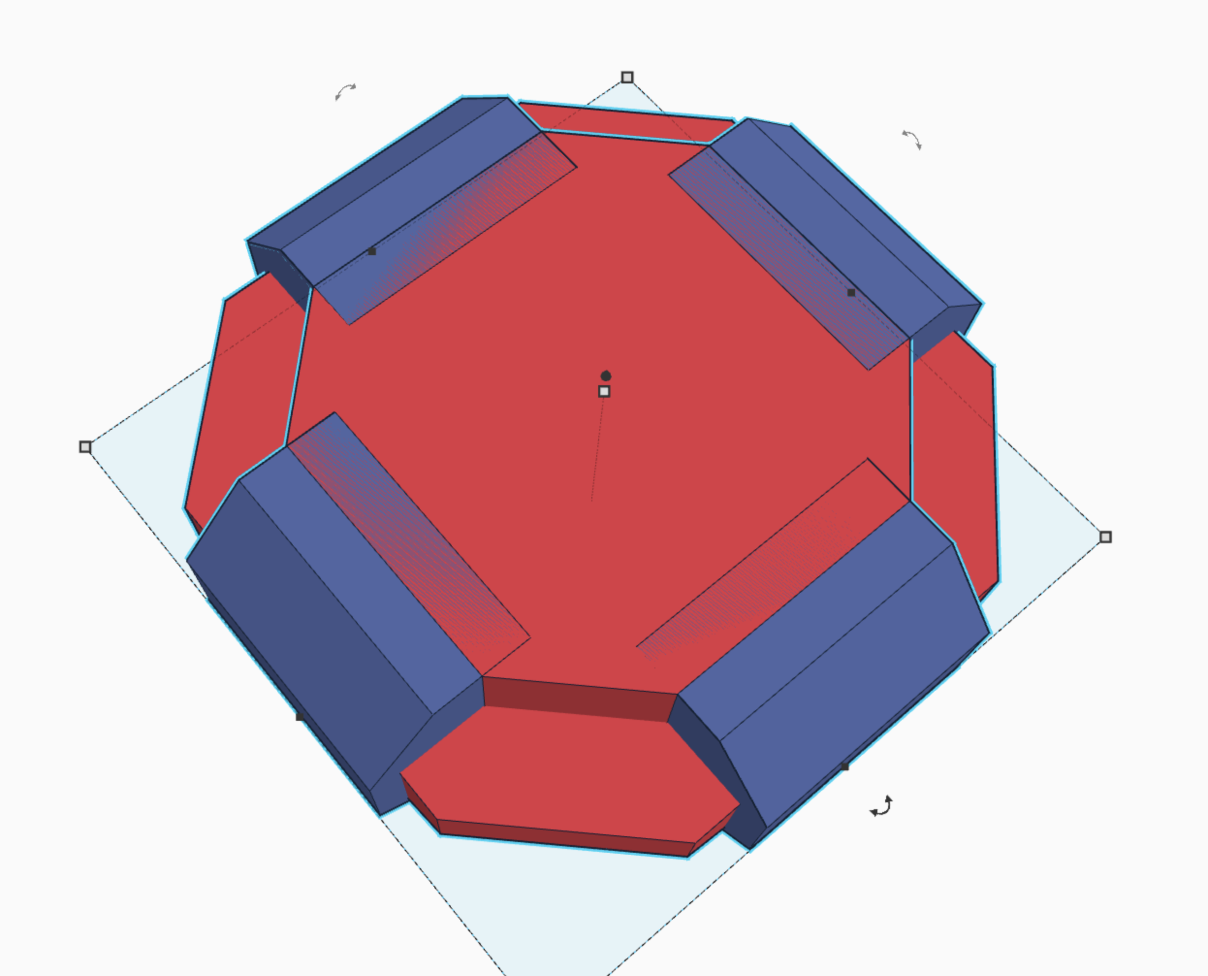
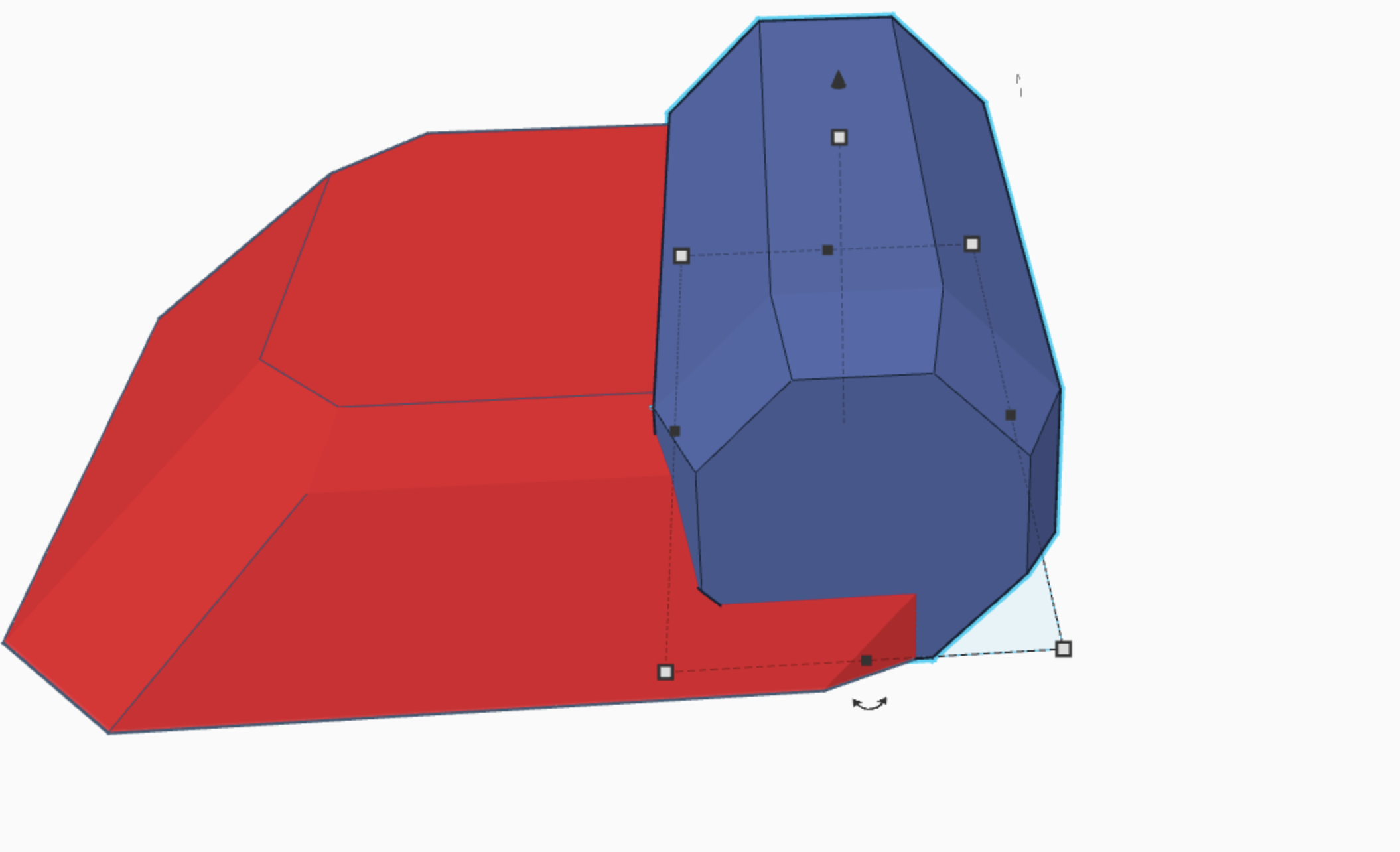
Fifth, place an octagon in the back of the cube, and put the bevel on full. (picture 6)
Sixth, take two more octagons with fully bevels, and cut the beveled part into the original octagon. (picture 7)
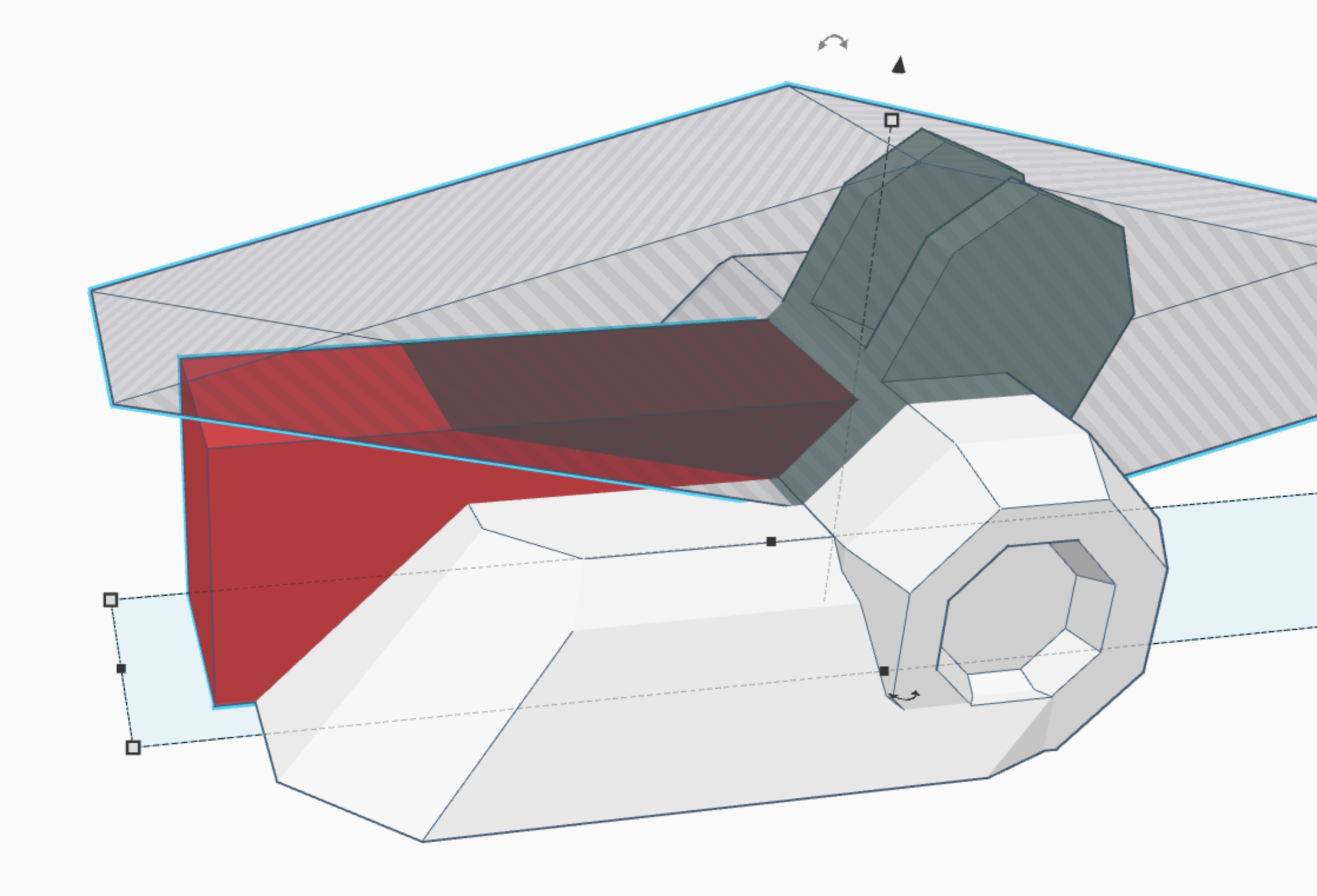
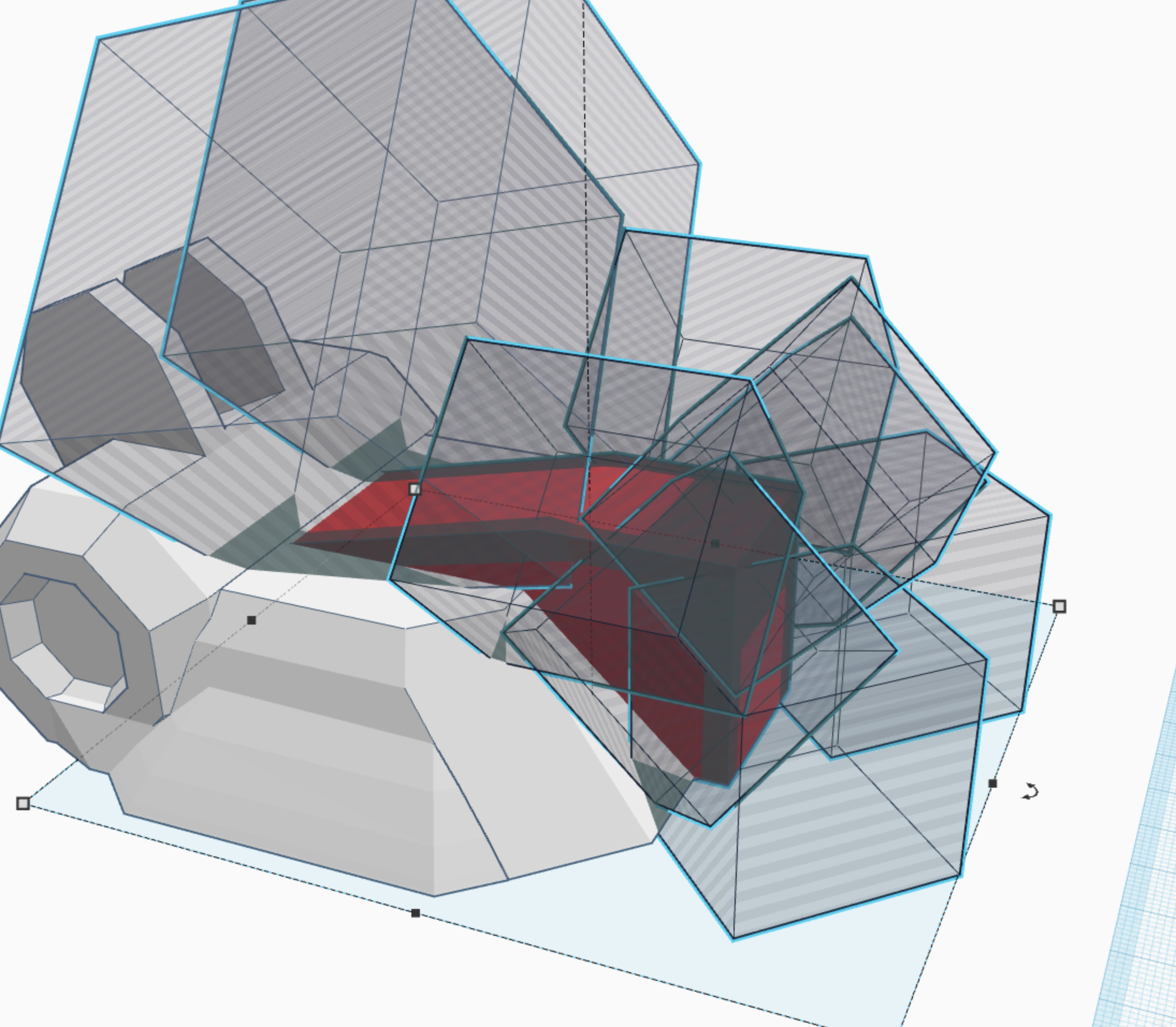
Seventh, place a cube on the back of the octagon at a 45 degree angle, and use another cube to cut out 1/3 of it right down the center. Be sure to cut out part of the octagon to. (picture 8)
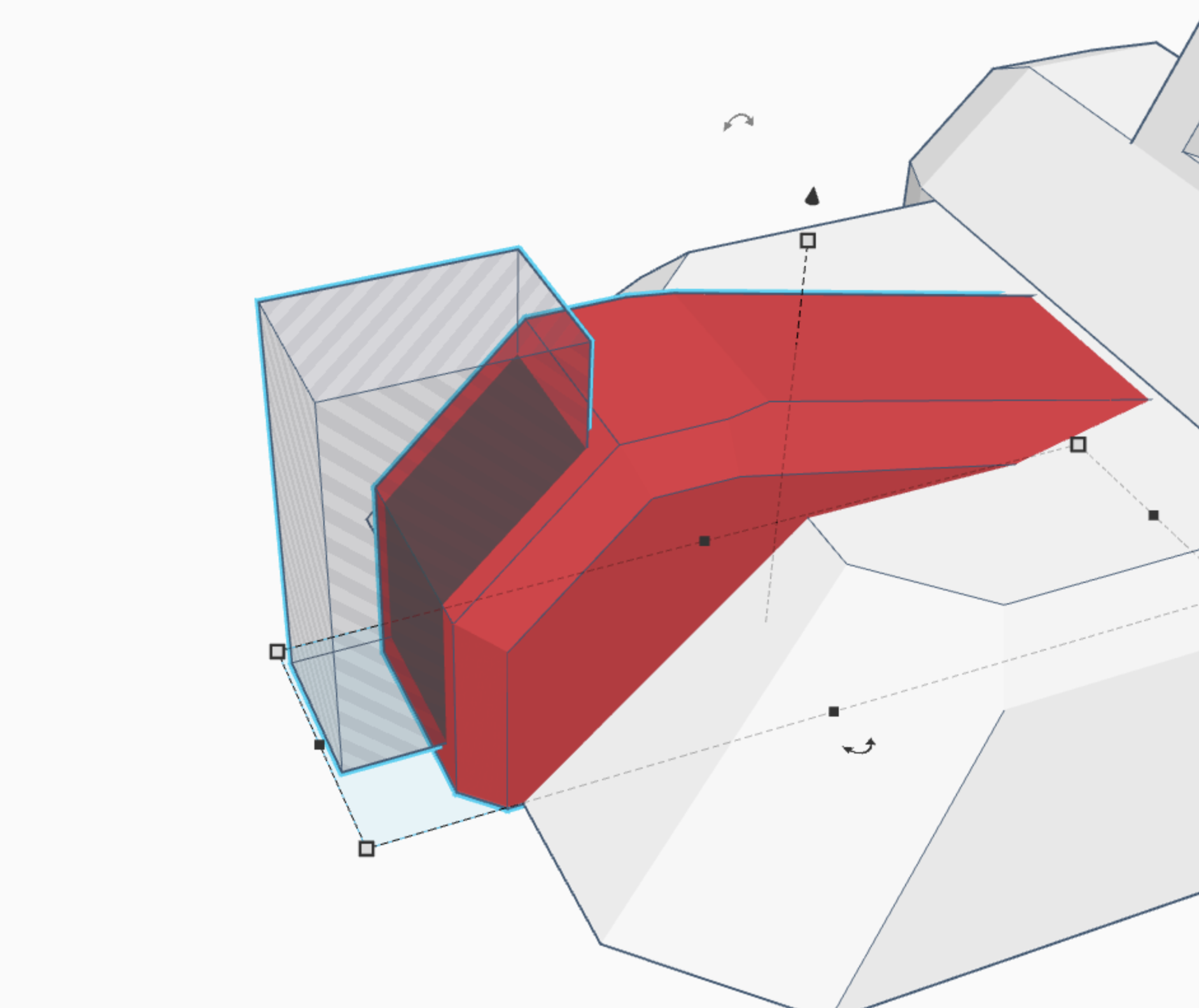
Eighth, take two more cubes, and cut off a 45 degree angled edge of the cube you just put on. (picture 9)
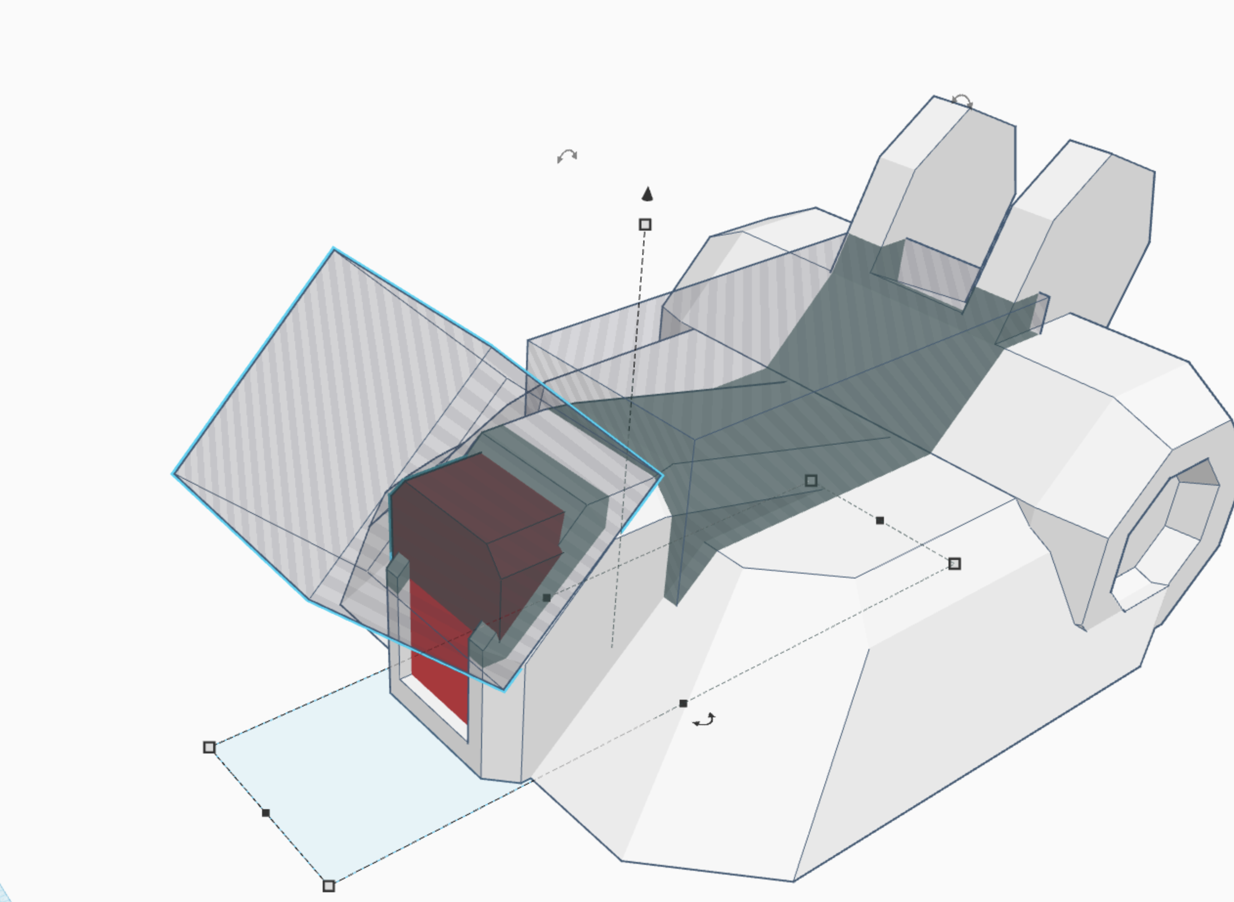
Ninth, place an elongated cube on the front of the body, and make sure it sticks out just a little way past the front. (picture 10)
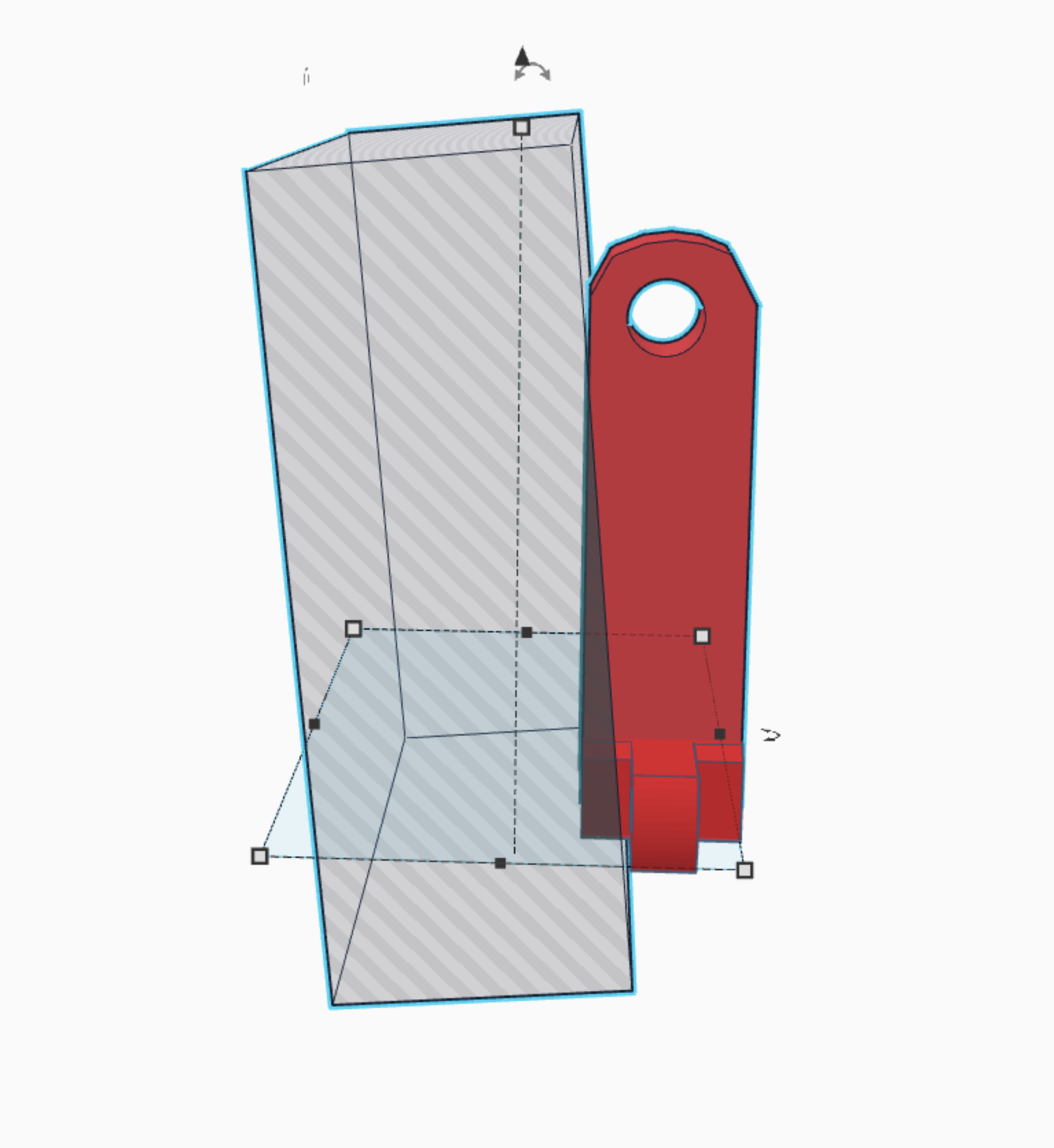
Tenth, cut that cube at an angle, but using a diamond shaped cube. (picture 11)
Eleventh, bevel all the edges of the cube, Including the front one, so that you have the shape sown in (picture 12, and 13)
Twelfth, cut a hole in the front of the cube we have been editing, to fit the cockpit. (picture 13)
Thirteenth, take a second cube, and bevel it as well, so that it can fit inside the cockpit to make a "glass" windshield. (picture 14)
Fourteenth, take a paraboloid, and change the settings so that there are only 8 sides. flatten it quite a bit, and then place in in the center of the body, so that only the left and right edges stick out to form more of an angle on the sides. (you MAY need to cut off the front depending on the steepness of the body.)(picture 15)
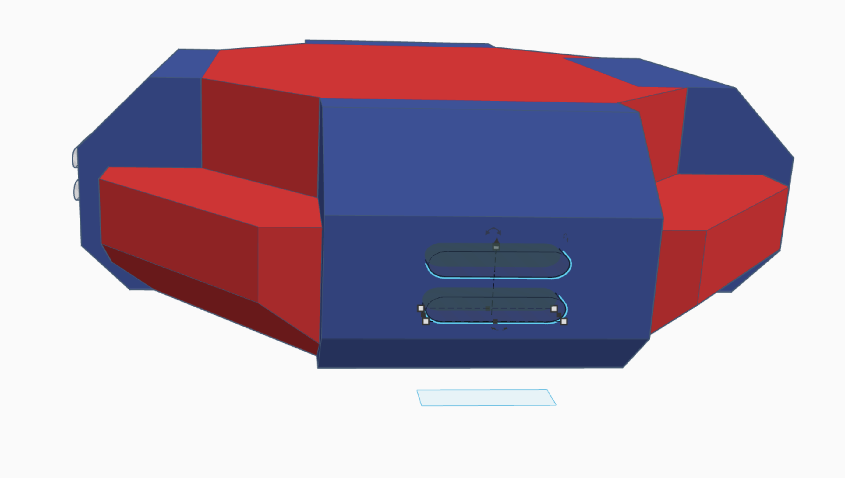
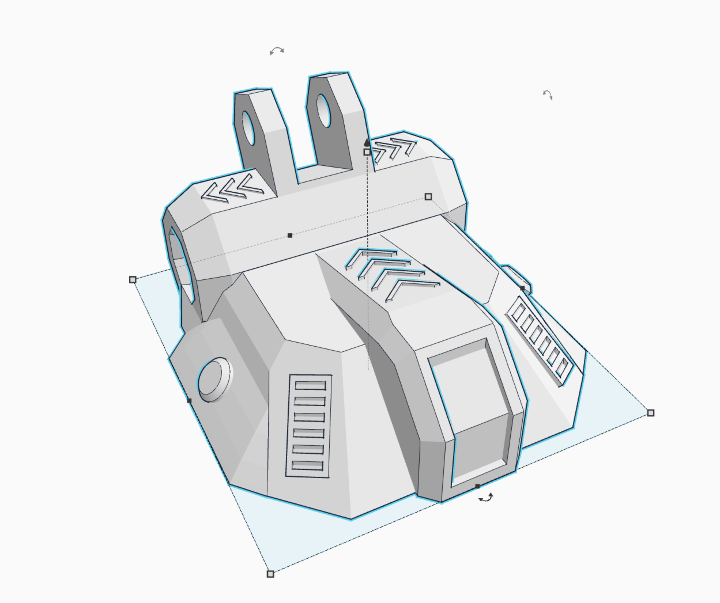
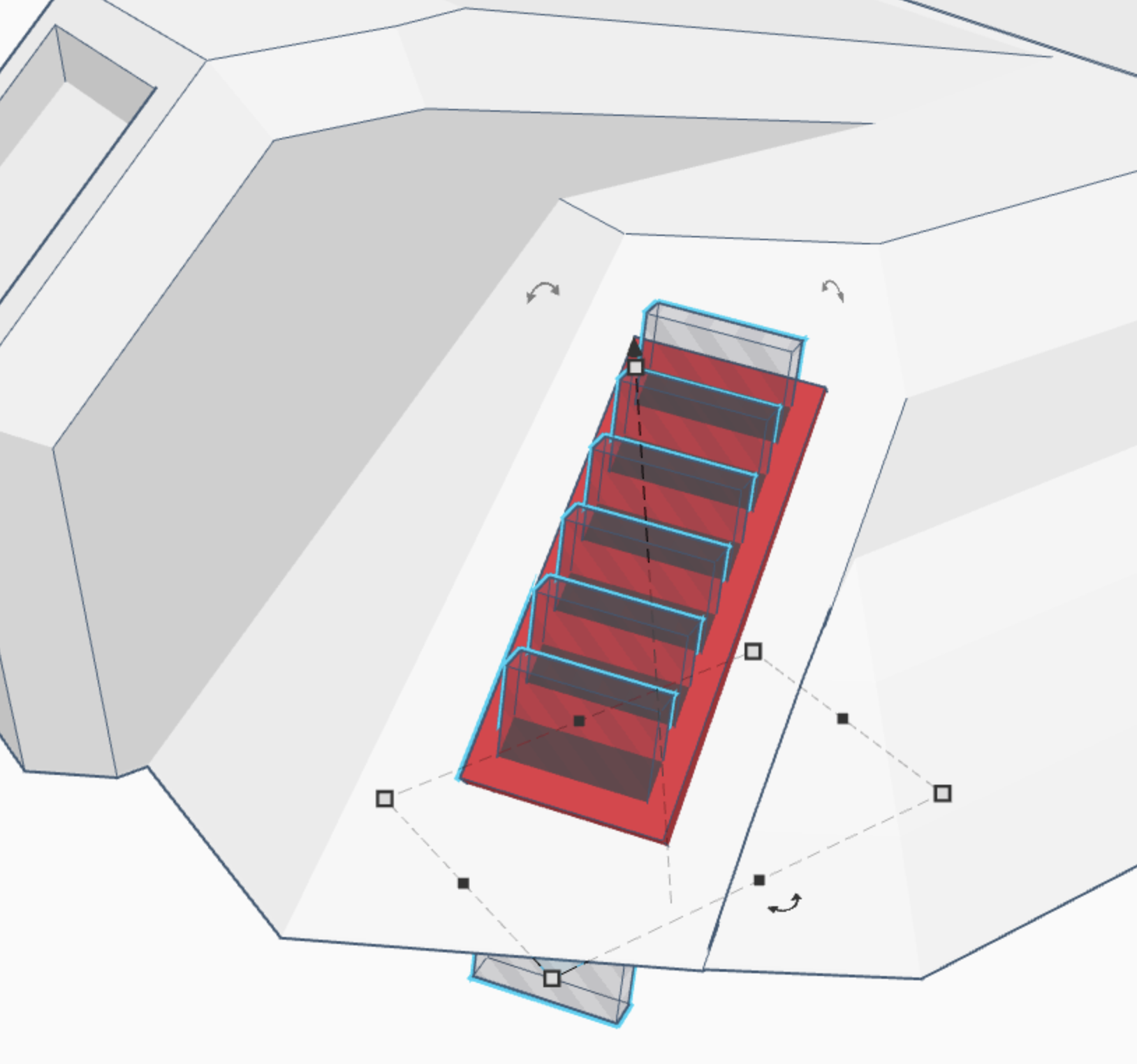
Fifteenth, put the grills on either side. To do so, all you need to do is make a cube on the edge, and then duplicate a smaller cube about 8 times along the center of the first cube. Then cut little holes into the first cube. This creates the grill. (picture 16)
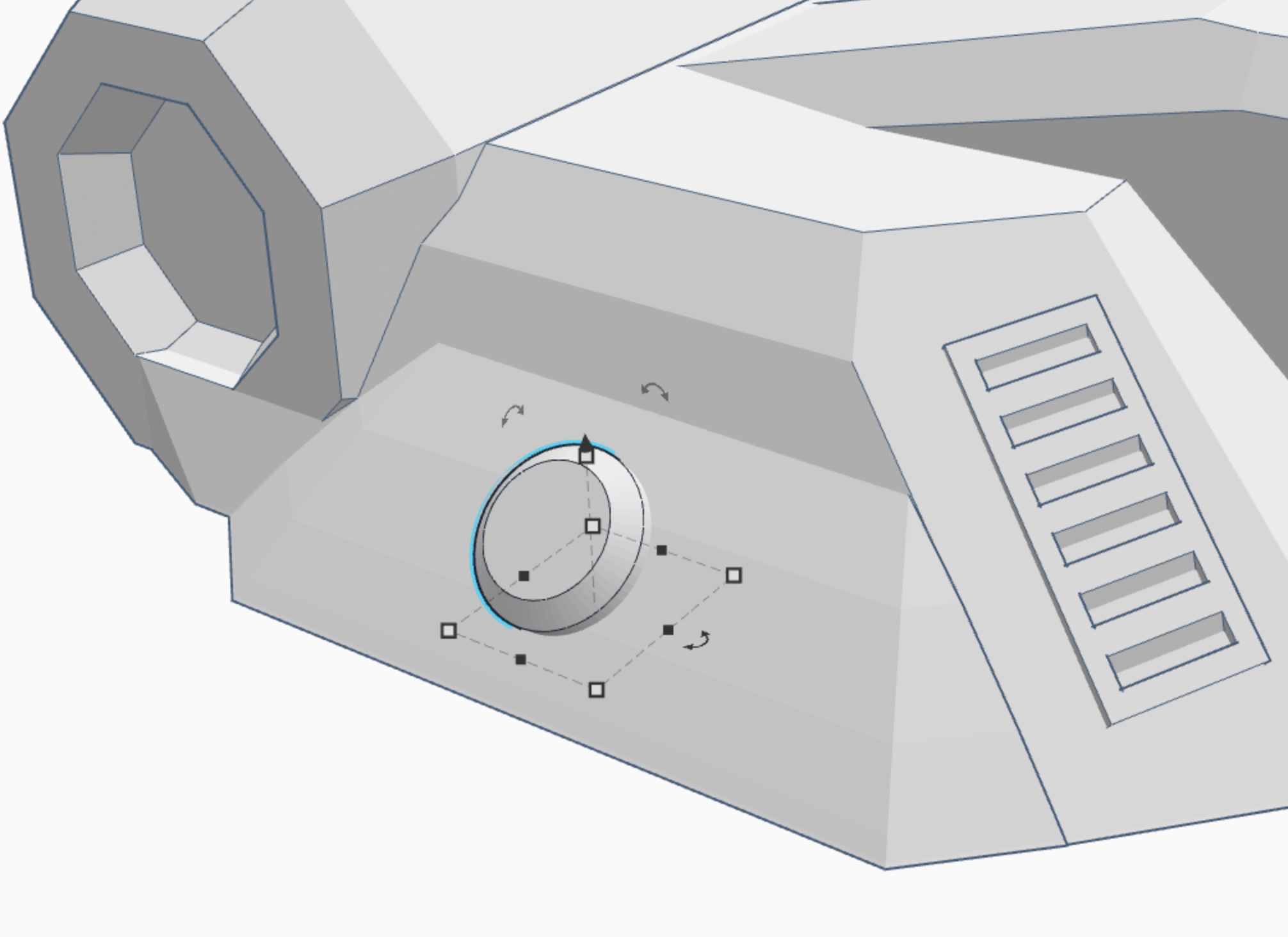
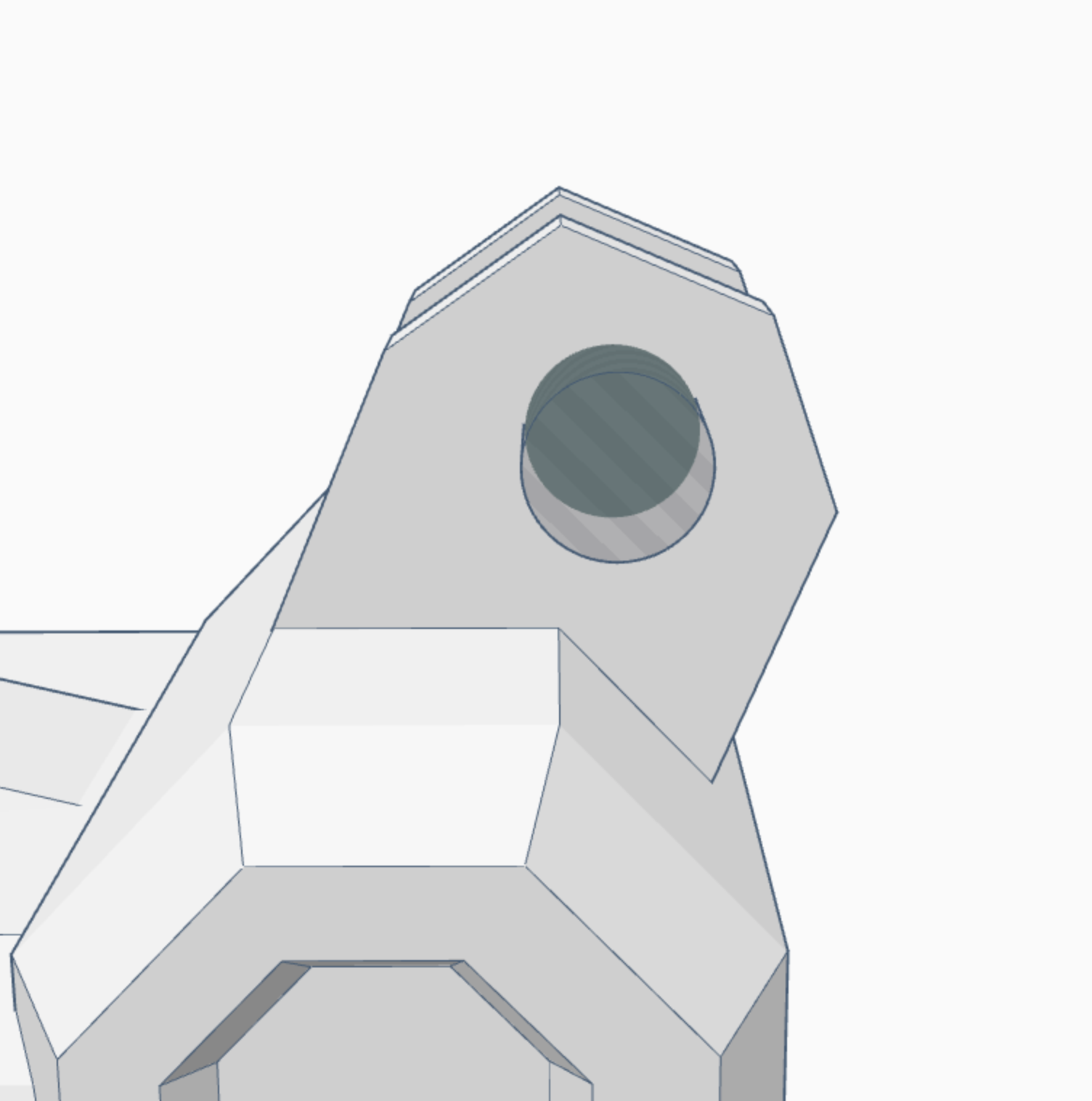
Sixteenth, cut a hole in the extended part of the body, so that you can fit the arm in it and attach it. Remember that the hole needs to be exactly the same size as the hole you made for the arm. (picture 17)
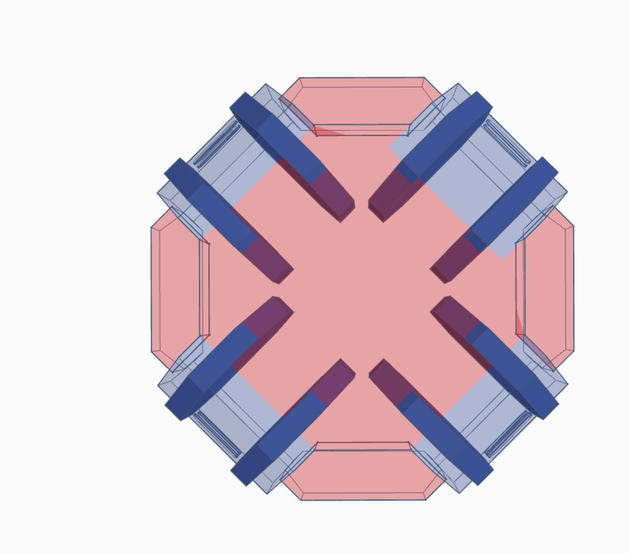
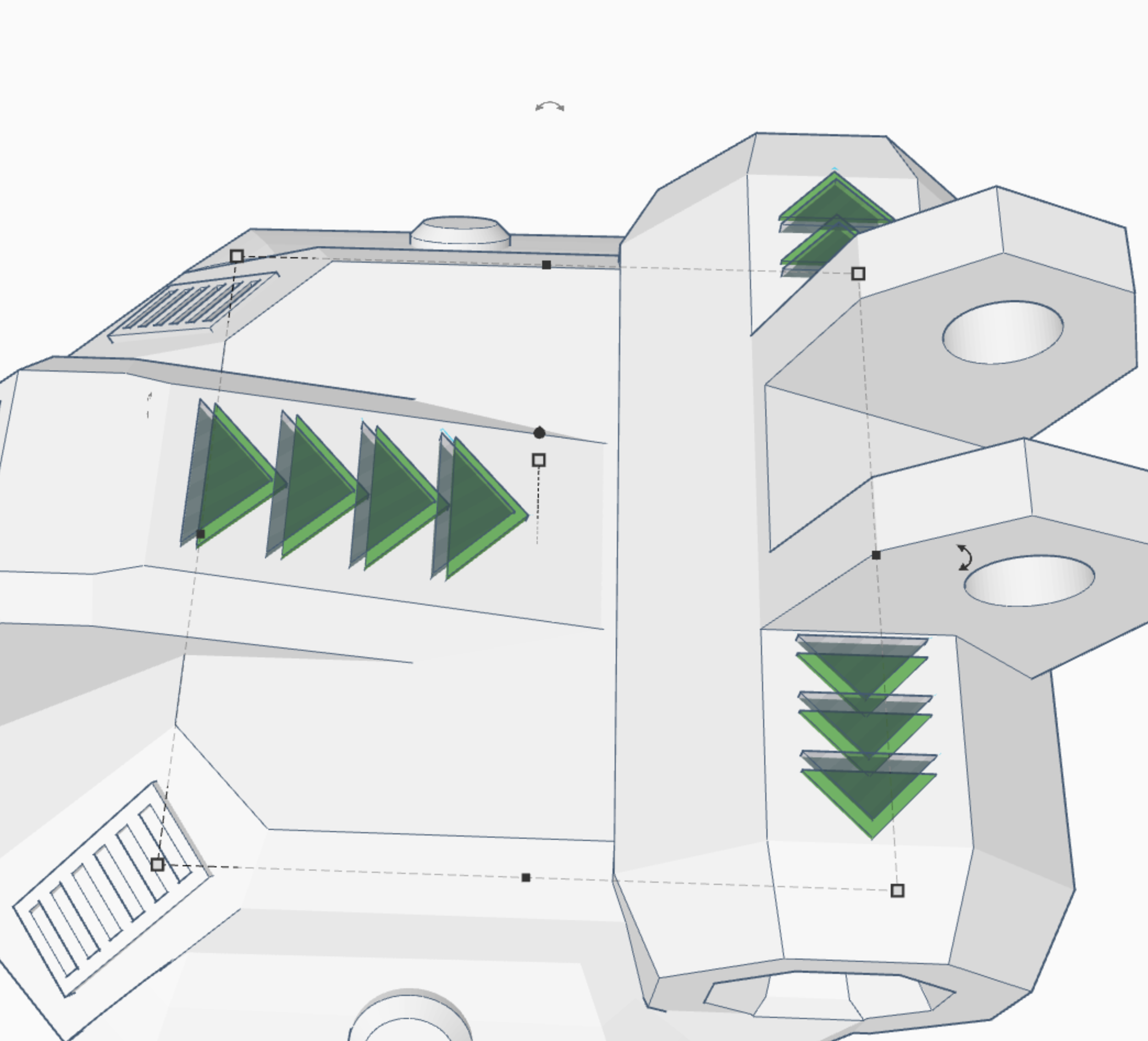
Seventeenth, take the roof shape, and cut it so that it forms an arrow looking shape, (as shown) then set them in three sets on top of the body. (for decoration.)(picture 18)
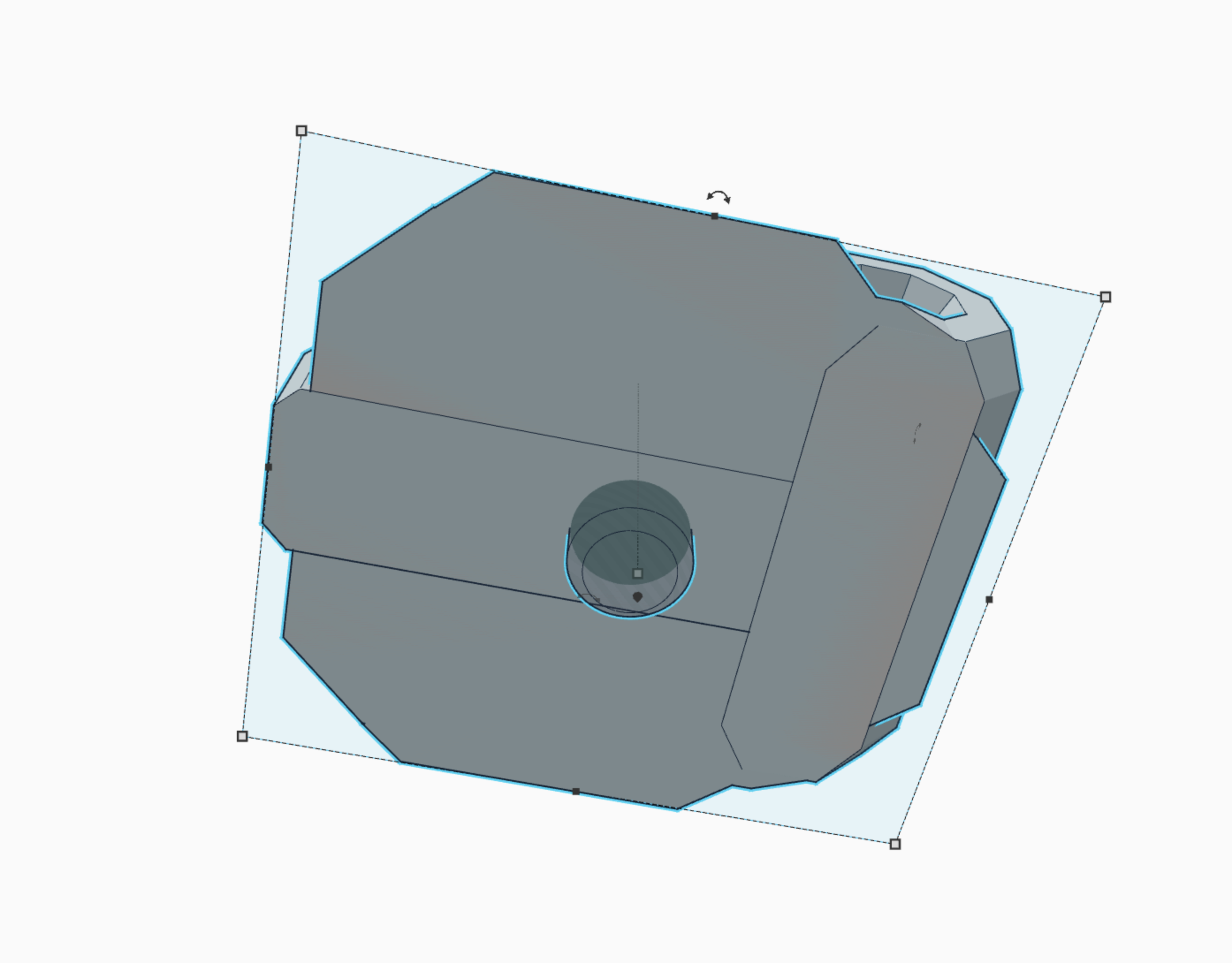
Eighteenth, take the cylinder that extrudes from the top of the base, and use it to make a hole in the bottom of the body. This will allow you to rotate the entire body when it is centered on the base. (picture 20)
WHEW! finally! were done with the construction aspect of the instructable! :)
Print!
Go ahead and print it out! I included all the stl,s you will need, remember the wheels get printed 4 times each, the claws, 4 times each, and each bracket gets printed twice. Also, yeah the files have weird names, I know... I was going to make something different, but changed the idea to this... :) lol :)
Downloads
PAINT IT!
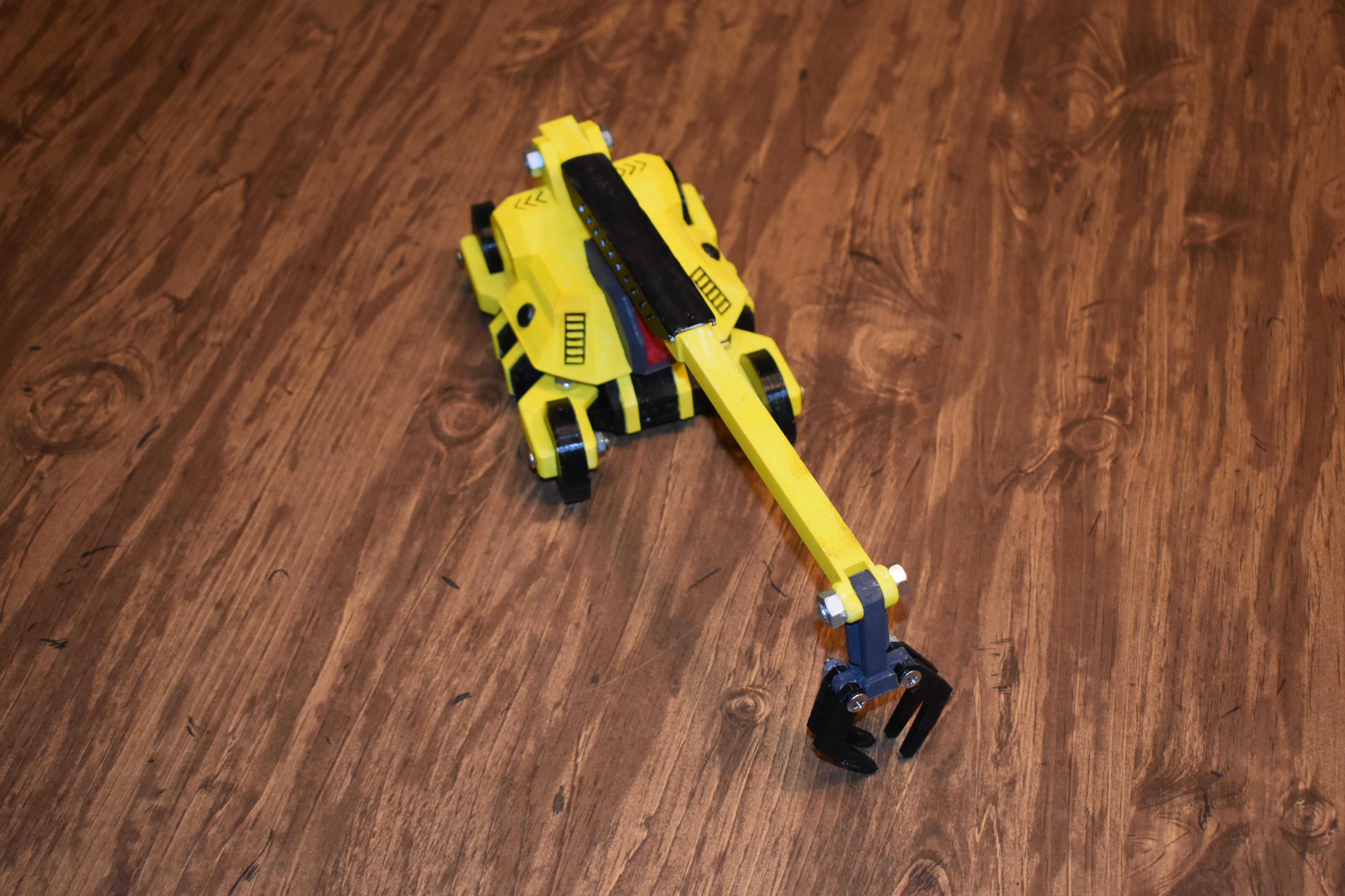
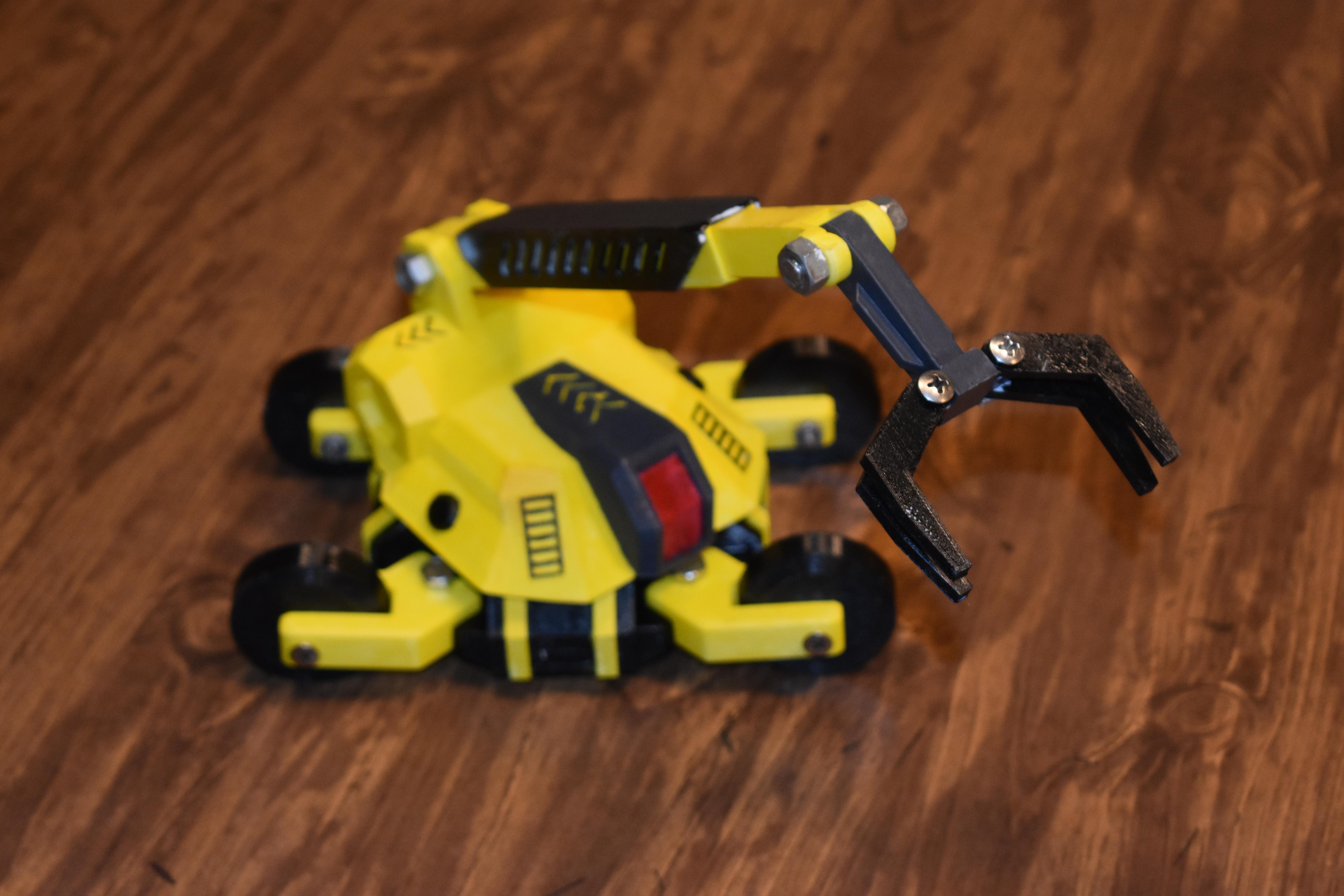
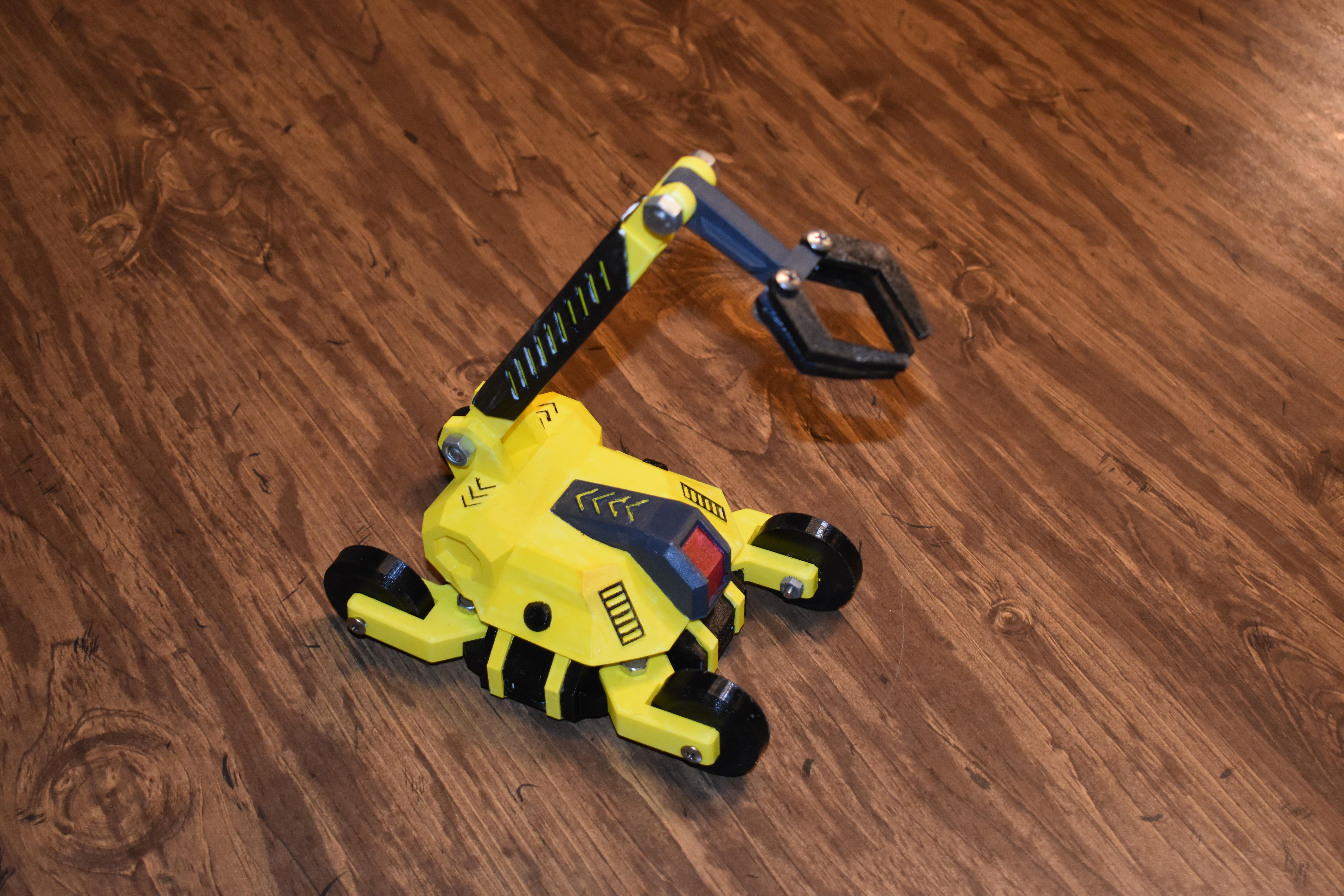
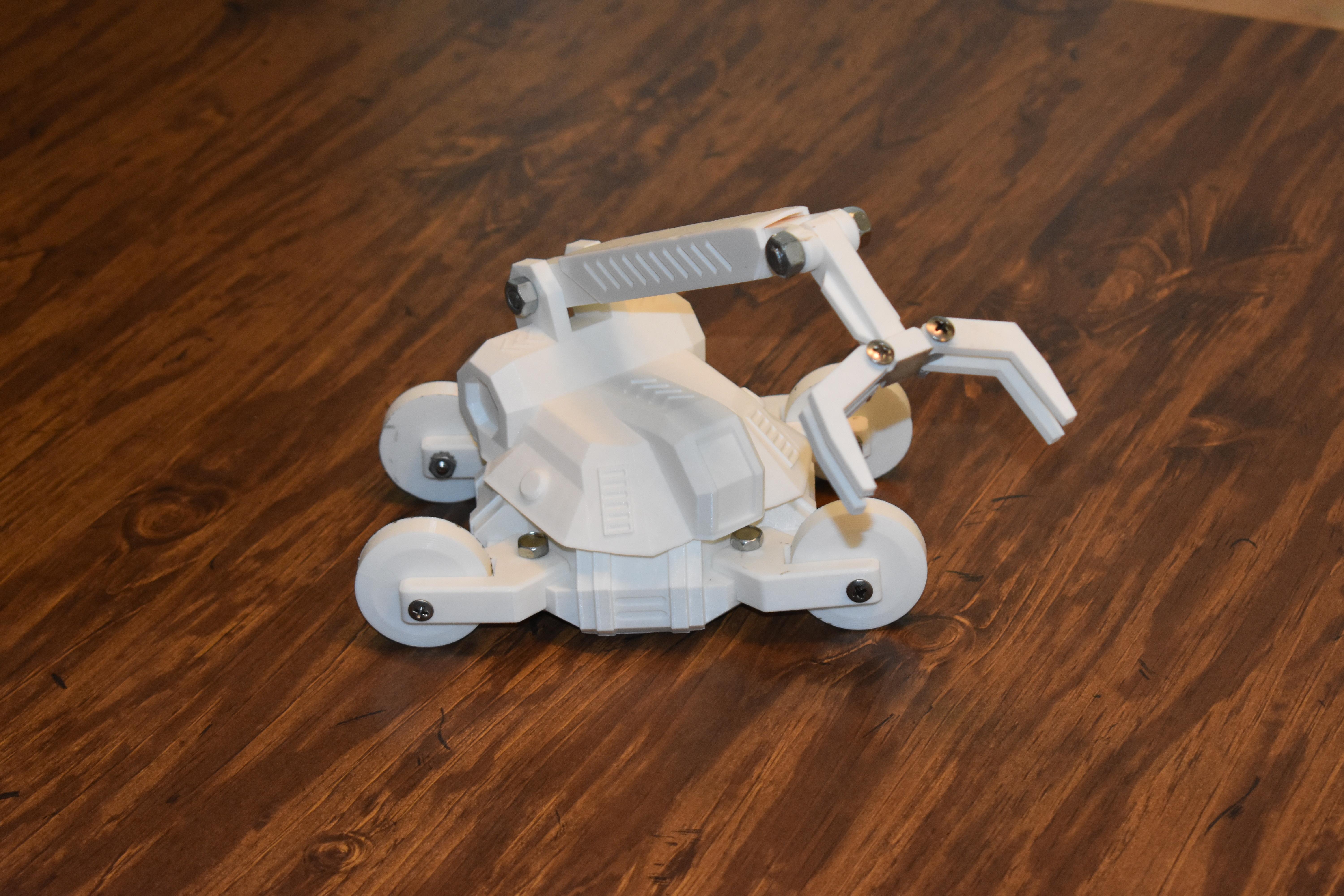
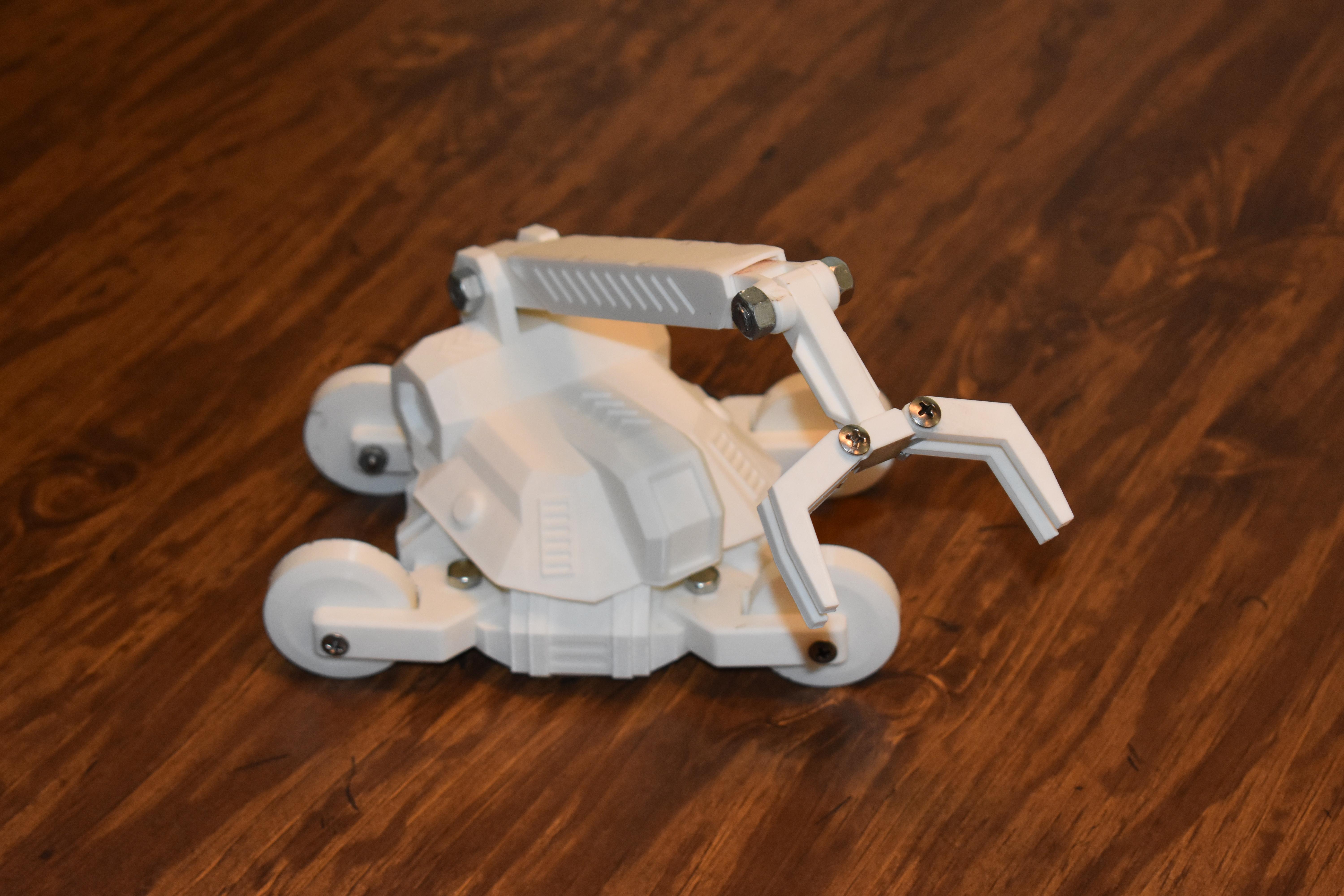
Go ahead and paint it. I used basic acrylic paint, and I think it turned out pretty well! enjoy!
Play, and Final Thoughts.
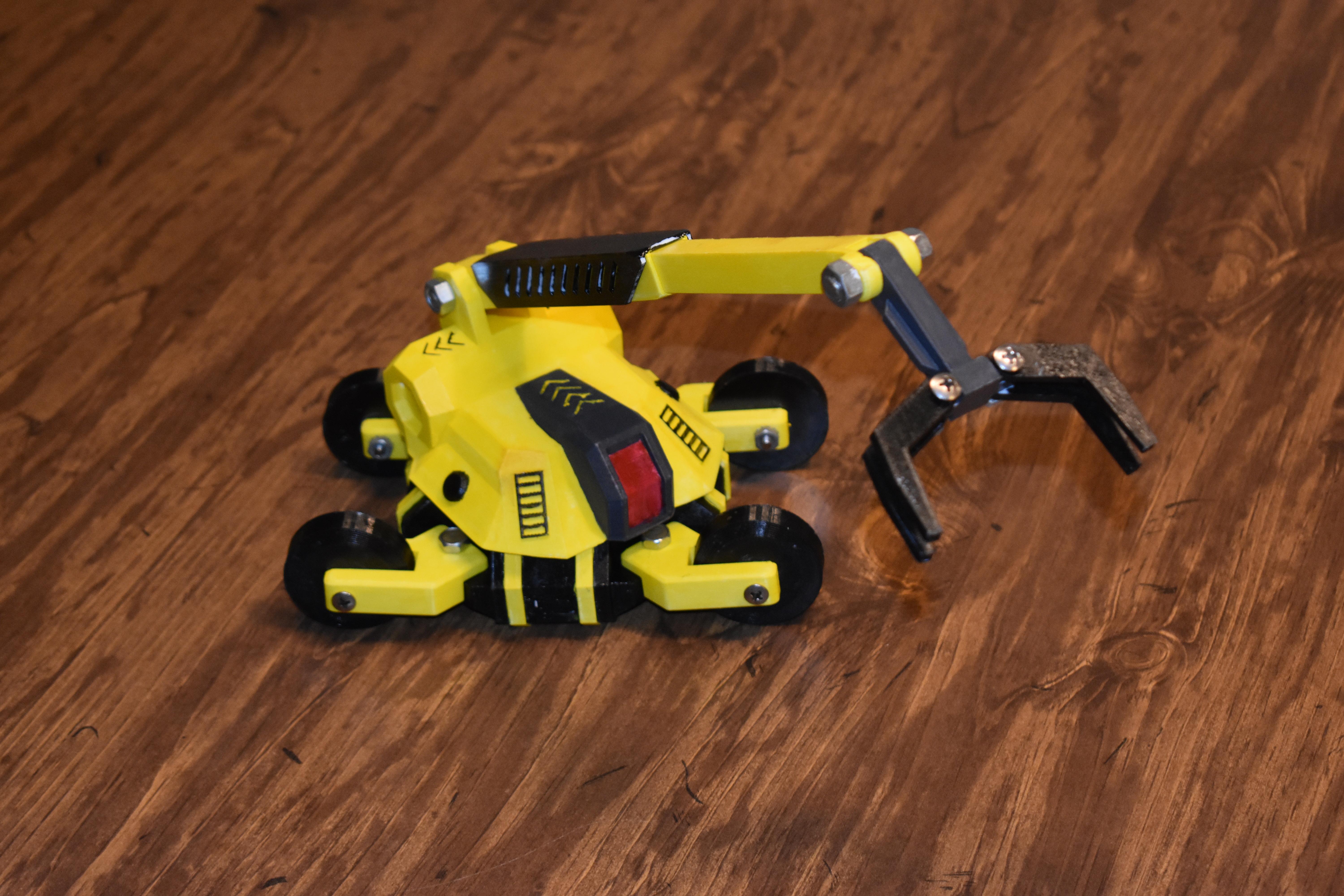
First enjoy playing with the toy.
Second, in retrospect, after creating this toy... I think I could have made the holes in the base deeper, I believe it would provide more support, but ultimately I drilled through the base with an electric drill and that worked out fine. Second, I think the hole in the bottom of the body could have been larger, and the cylinder extruding from the base could have been larger as well. This would also provide more stability. But all in all I think it turned out very nicely :)
HAVE FUN! AND THANKS FOR READING! :) if you print this out, I'd love to see pictures! :) thanks!
(and thank you instrucables and tinkercad team for making all of this possible :)