3D Self-watering Planter
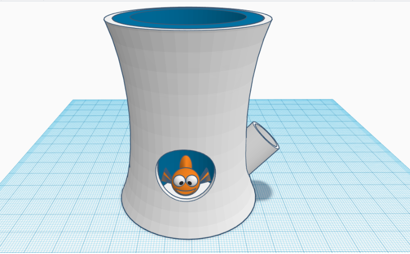
In this instructable, I will show you how I designed a simple and funny self-watering planter. For this I used Tinkercad to create this 3D model. Essentially, this self-watering planter are divided into 3 parts, namely the water reservoir, the planter and a funny fish that indicate the water level.
Basic Reservoir Structure
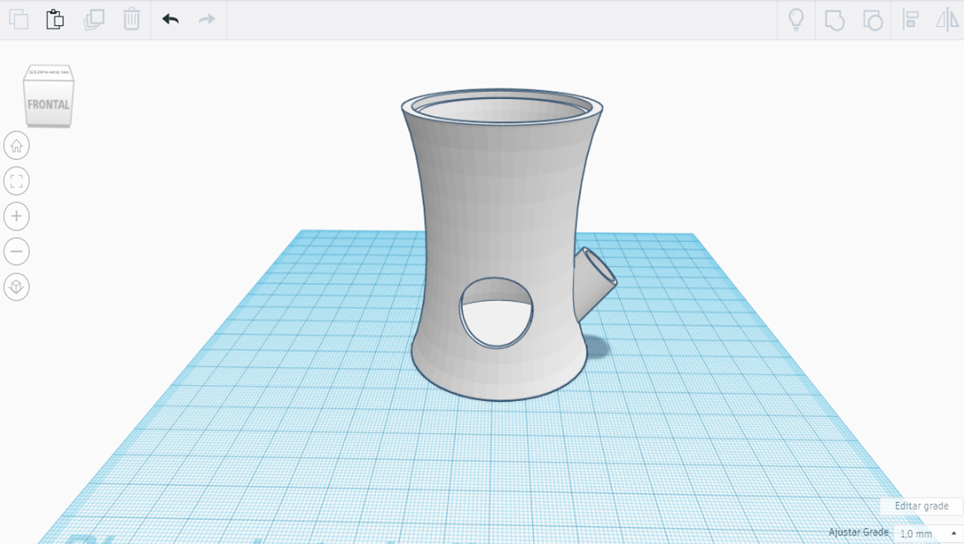
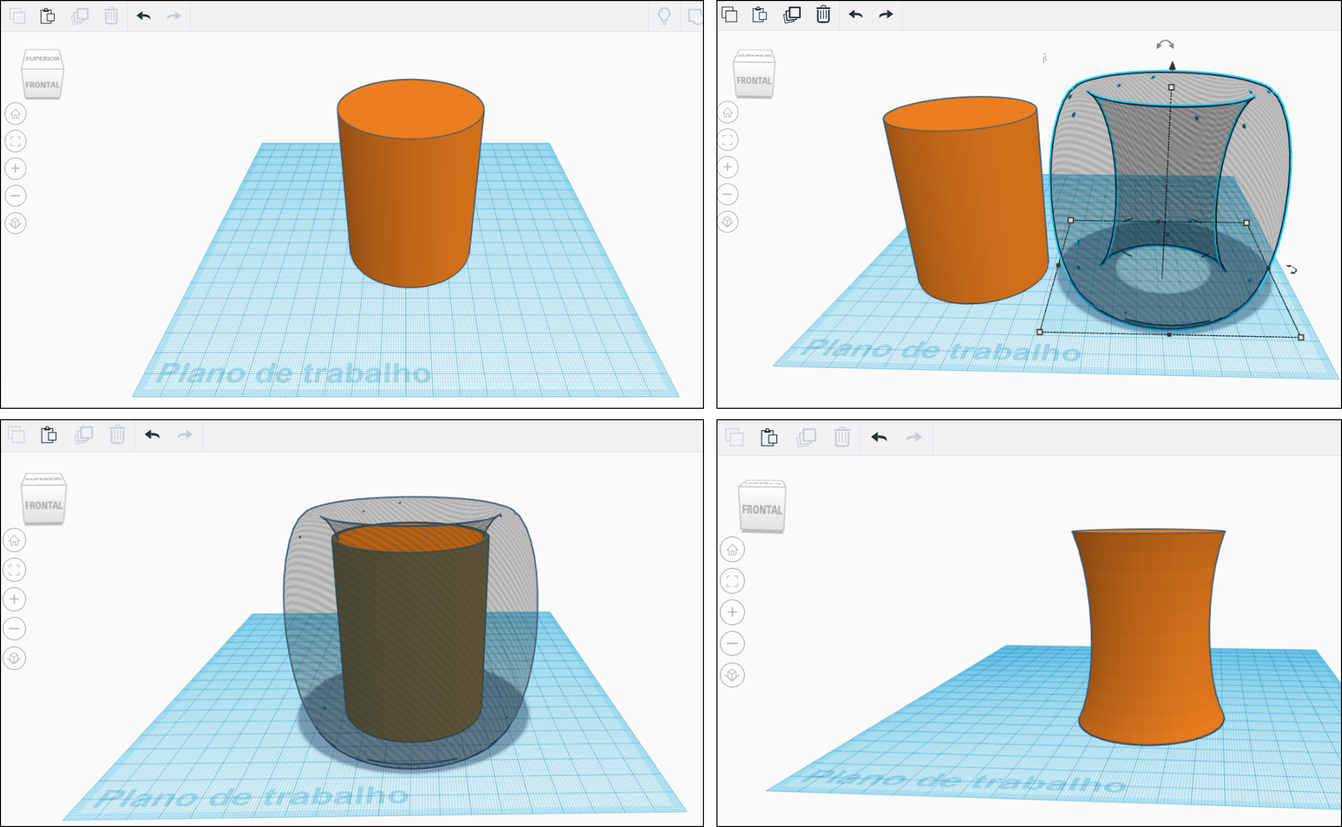
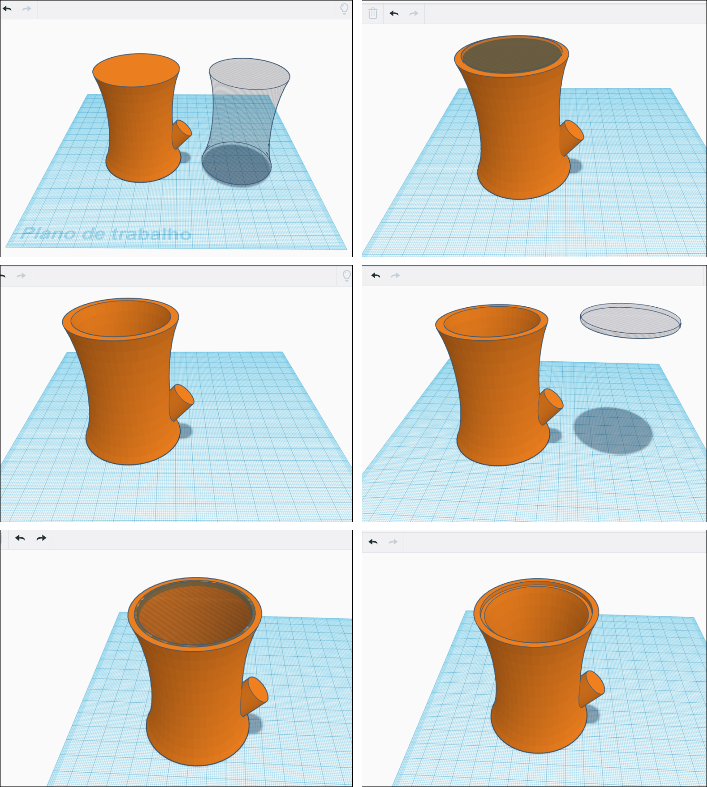

1. Start by creating a cylinder with 60 mm of diameter and 75 mm of height.
2. Create a SVG revolver (go to Shape Generators, select Featured and choose the SVG revolver) with the follow characteristics:
- sketch height: 9.52
- Internal diameter: 15.39
- number of sides: 48
- croquis rotation: 0
- revolution angle: 360
Note: Set the SVG revolver shape to be a "Hole". This will be the cutout shape used to create the external area of the planter.
3. Align the SVG revolver shape to the center of the cylinder. Use the align tool to adjust both objects.
4. In the menu click Group to combine the shapes together and cut out the external part of the cylinder.
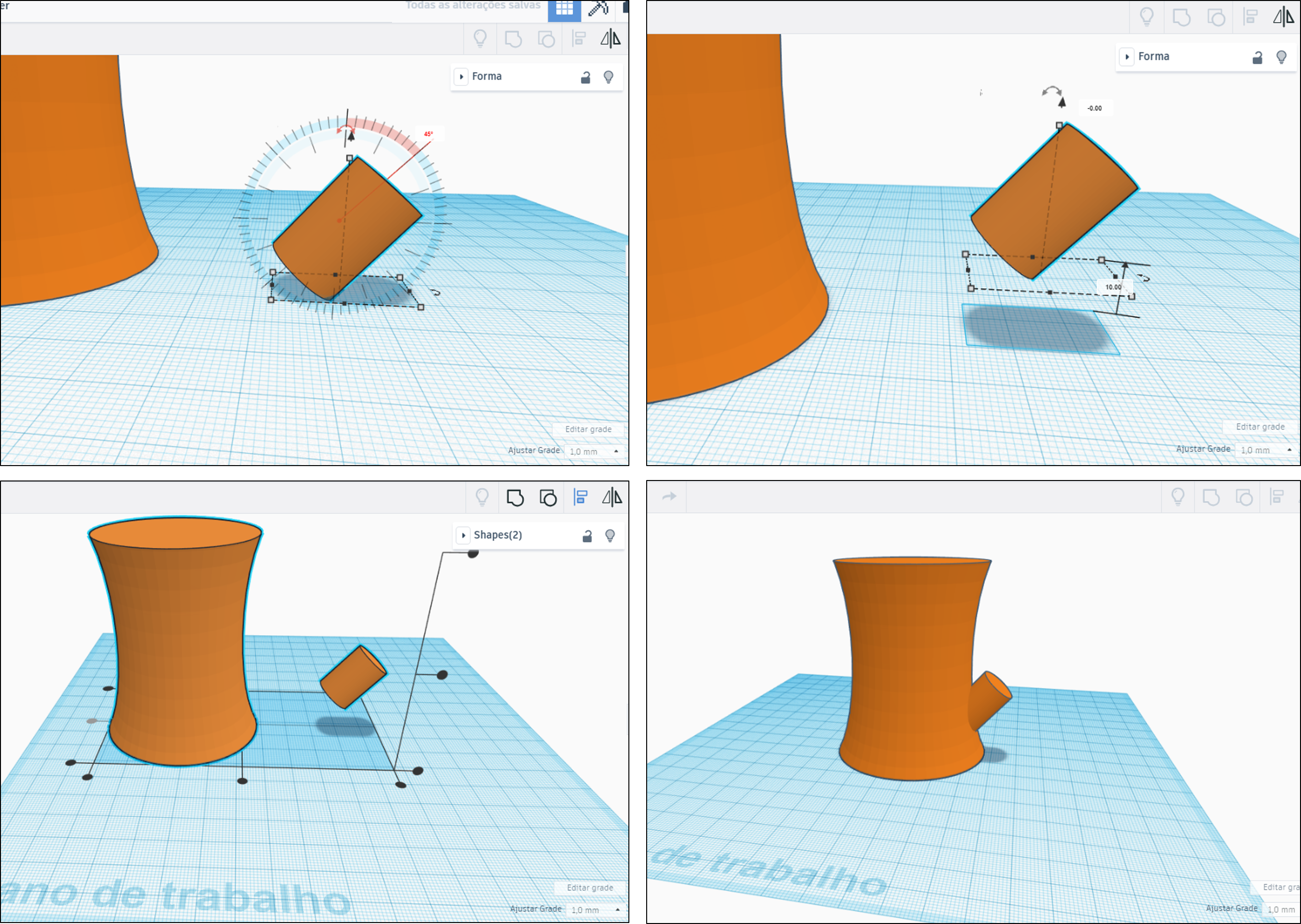
5. Create a small cylinder with 15 mm of diameter and 21 mm of height. Now rotate the cylinder 45º around the vertical axis and then drag it 10 mm above the work plane.
6. Align both cylinders in the horizontal axis and then drag one of them until obtain the final shape of the reservoir structure (see the figure). Before group both cylinders copy the larger cylinder (this will serve to create the interior of the reservoir), and then group the cylinders.
7. Once grouped, now we can past the larger cylinder and adjust the diameter and the height for 53 mm and 73 mm, respectively. Set this cylinder shape to be a "Hole", and drag it 3 mm above the work plane. Then align it with the larger cylinder of the planter structure and group them.
8. To create the support for the planter (the internal part where we will place the plant), we need to make an internal edge on the top of the basic structure. For this, create an empty cylinder with 52 mm of diameter and 2 mm of height. Then align it with the top of the structure and group them (see the figure).
9. The tube through which the water enters the reservoir, is made by creating an empty cylinder with 13 mm of diameter and 30 mm of height. Now rotate the cylinder 45º around the vertical axis and then drag it 10 mm above the work plane. Align it with the lateral cylinder of the basic structure and group the set.
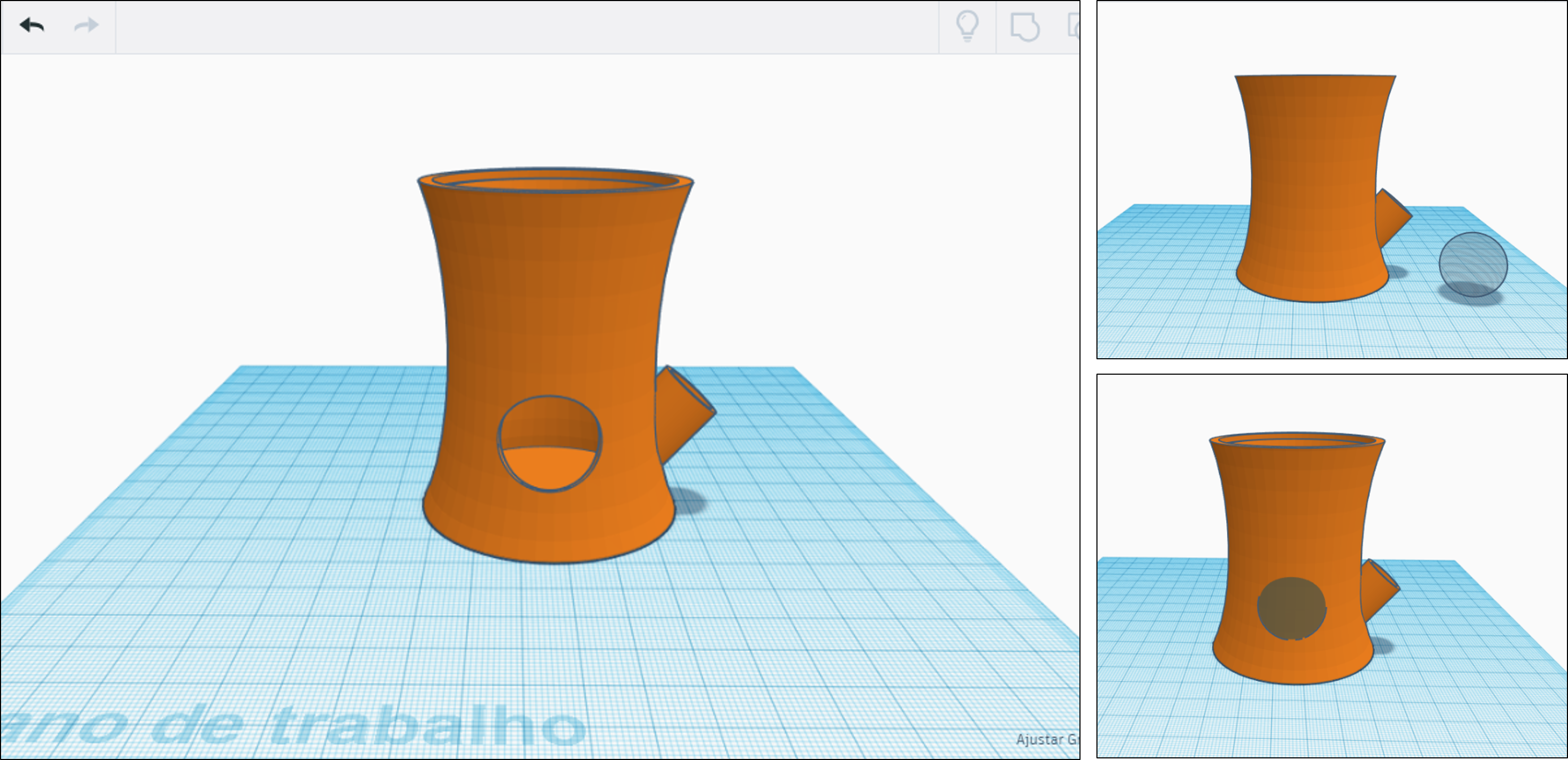
10. To finish the basic structure we need to create a round hole in the front of the planter. This will serve to see the level of water. To make this, add a sphere with 22 mm of diameter and define it as a hole. Now drag it 13 mm above the work plane, place it in the final position (see the figure) and group the set.
Basic Planter Structure
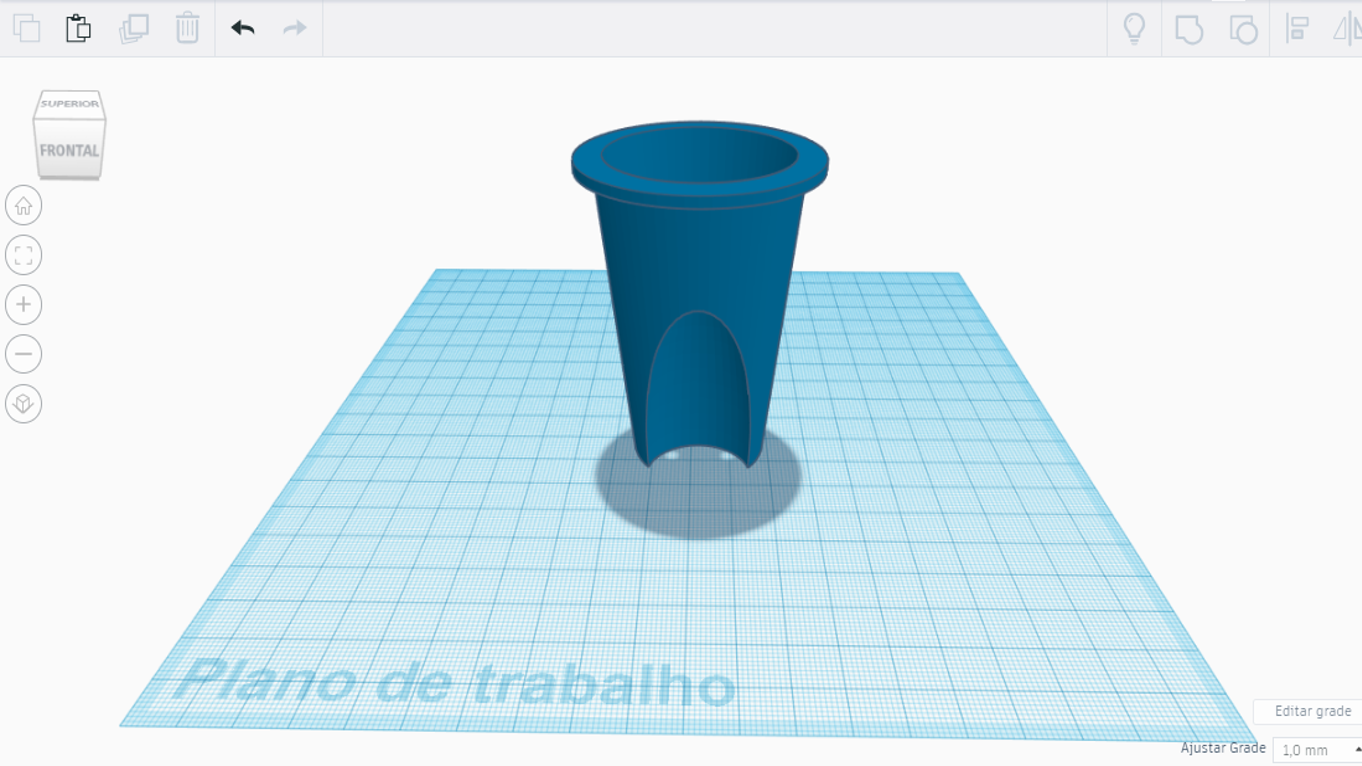
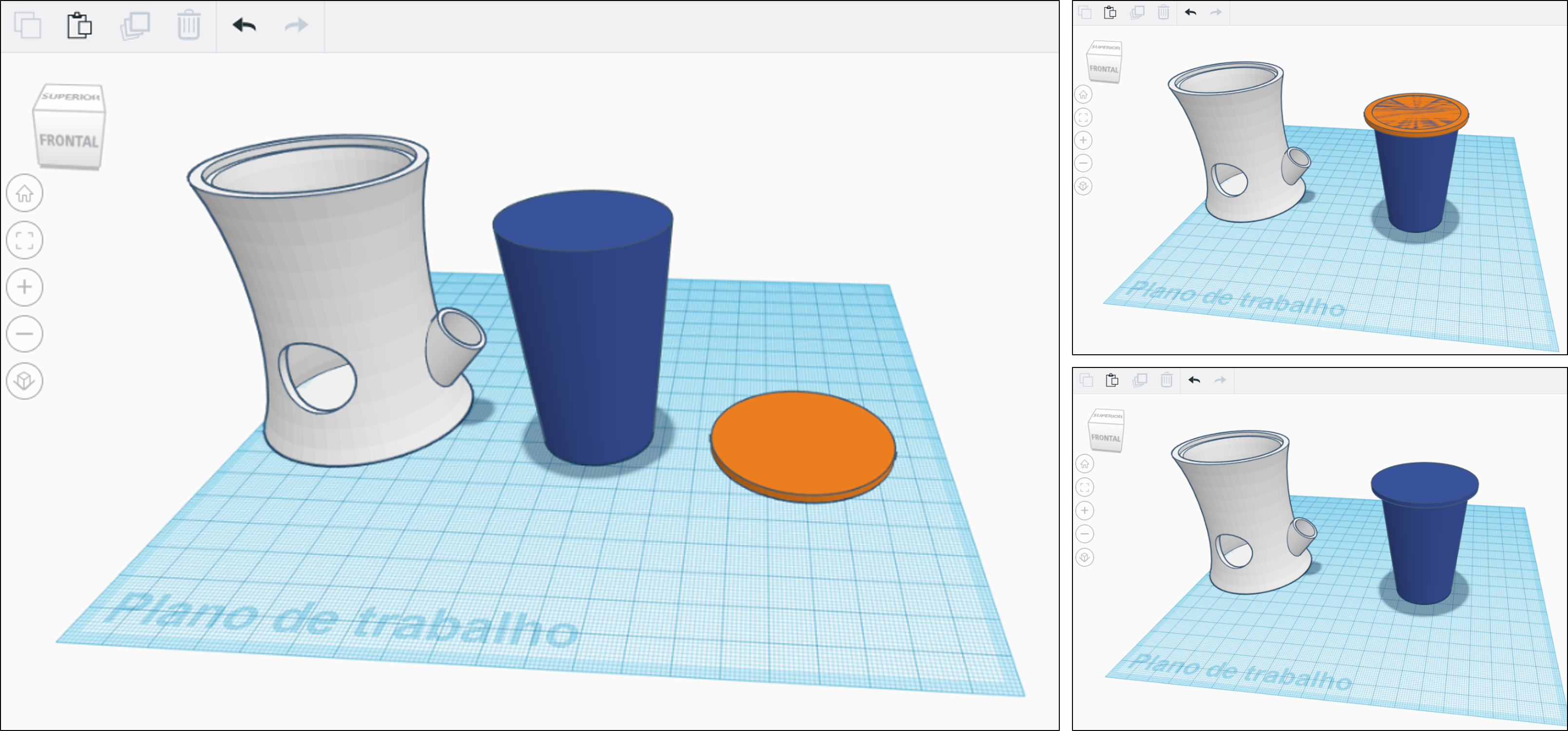
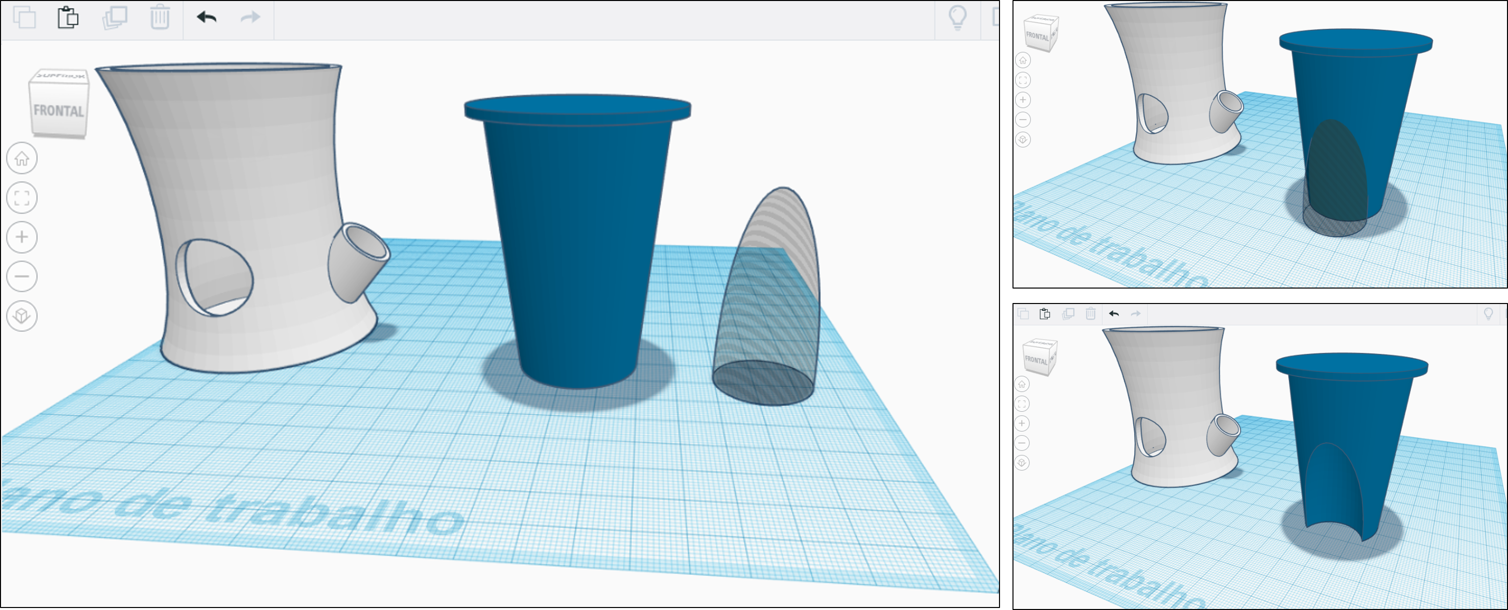
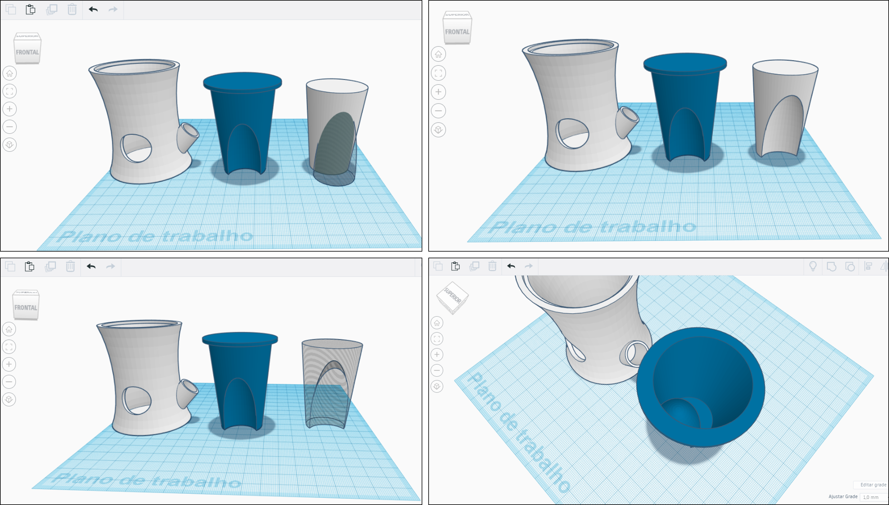

1. Start by creating two cylinders:
a) A cylinder with defined smoothness (go to Shape Generators, select All and choose the cylinder with defined smoothness) with the following characteristics:
- Diameter: 44.1 mm
- Height: 65 mm
- Base radius: 6.32
- Top radius: 9
- Divisions: 100
b) A cylinder with 52 mm of diameter and 2 mm of height.
2. Align both cylinders in the horizontal and vertical axis. The smaller cylinder should be aligned with the top of the larger cylinder (see the figure). Now we can group both shapes.
3. Create a paraboloid shape with 25 mm of diameter and 50 mm of height. Set this shape to be a hole, align it with planter structure, as shows the figure and then group.
4. To make a hole in the basic planter structure, create a cylinder with defined smoothness, quite similar to the step 1, but with 41 mm of diameter and 62 mm of height. At the same time create a paraboloid shape (in the hole form) with 29 mm of diameter and 54 mm of height. Then align it with the cylinder shape (as in step 3) and group both shapes. Now, define this shape as hole and align it with the basic planter structure at the top and group them.
5. Now the last thing left with the planter part is to make two holes for the wick to fit in. For do this, create two empty cylinders with 4 mm diameter and 10 mm of height align them and group with the basic planter structure.
Funny Water Level
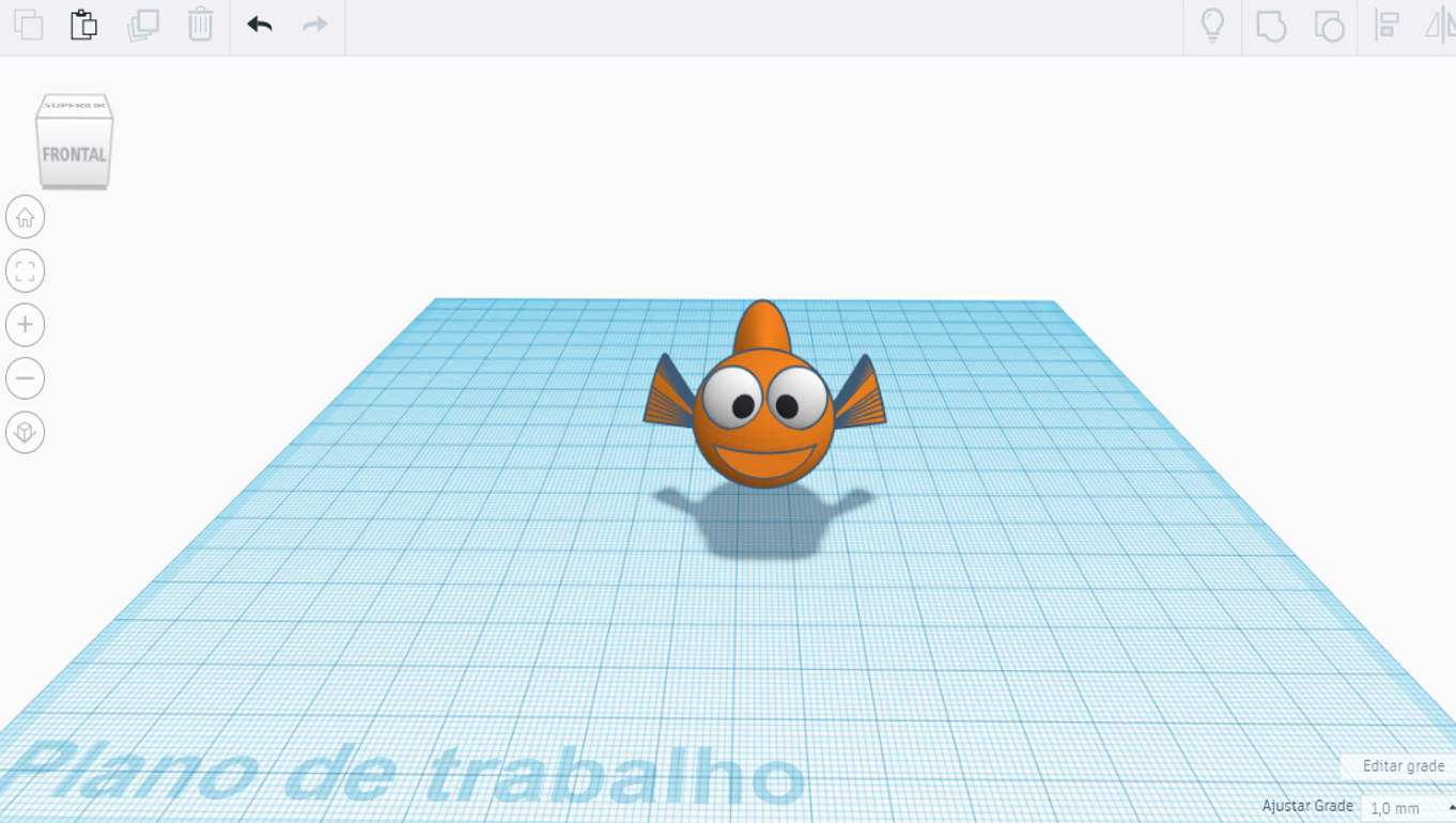
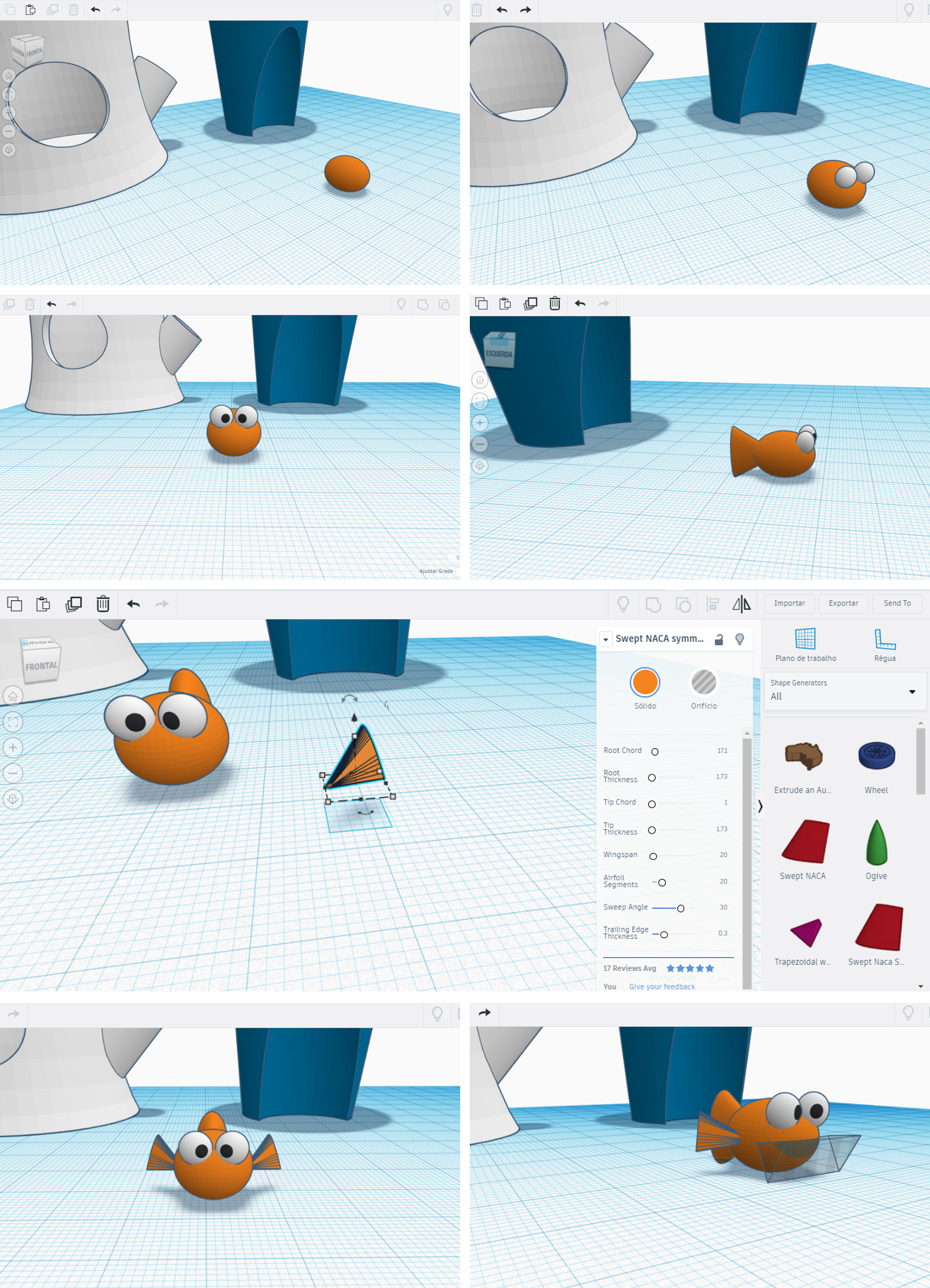
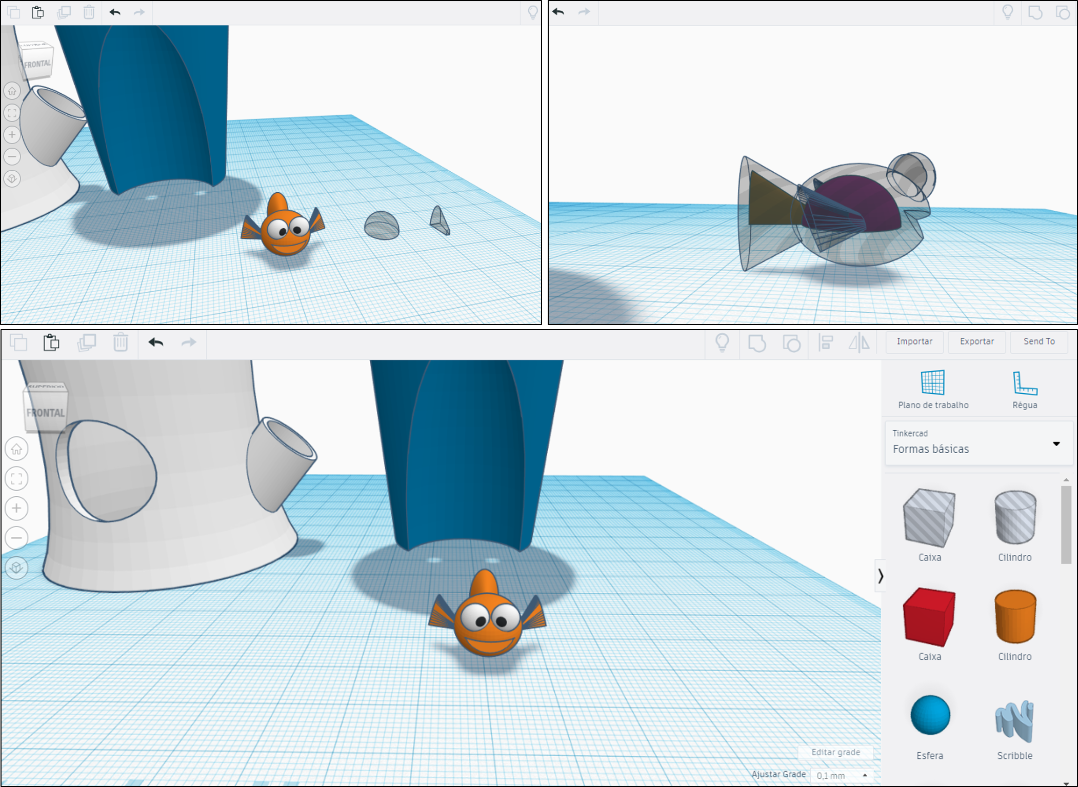
With Tinkercad you can easily download animals and other funny objects, from the gallery, or simply design your object. In this step, I created a funny fish with basic shapes.
1. Start by creating an oval shape as showed in the figure. This shape will the character body.
2. To make the fish’ eyes, start by create two smalls spheres and adjust them in the body, as shown in the figure. Once in position, create two other spheres and fit them inside the previous spheres.
3. To create the fish tail, we can use the cone shape. Note the base radius is major than the top radius. Then we can adjust it on the body of the fish.
4. Similar to tail, the fish fins can be made with the cone shape. However, we can use the Swept Naca shape (go to Shape Generators, select All and choose the Swept Naca). From my point of view, this shape is the one that best fits the character.
5. To make the mouth, insert a roof (in the hole form) as showed in the figure and then group all parts of the fish.
6. Finally to make the fish floatable, we need to create a hole inside the body and the tail. For this we can use a half sphere (in the hole form) and adjust it to the fish body. For the tail we can simply copy/past the tail and cut it to a half and define it as hole. Then adjust it as shown in the figure and then group them.
Project File
Completed 3d Project file can be found on Tinkercad: