3D Printing a Curved Shell for a Teapot Handle
by rich.altmaier in Workshop > 3D Printing
1837 Views, 3 Favorites, 0 Comments
3D Printing a Curved Shell for a Teapot Handle
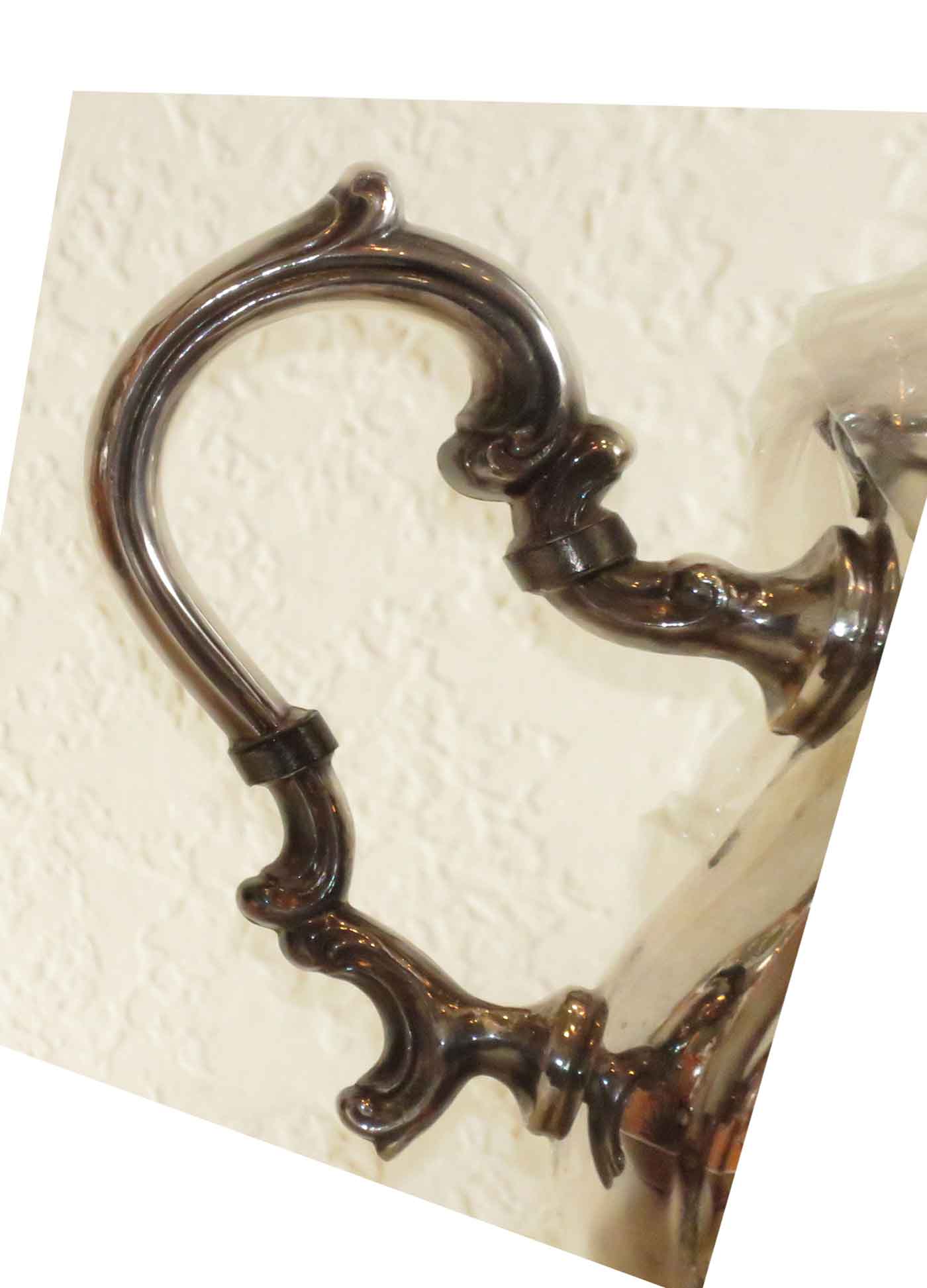
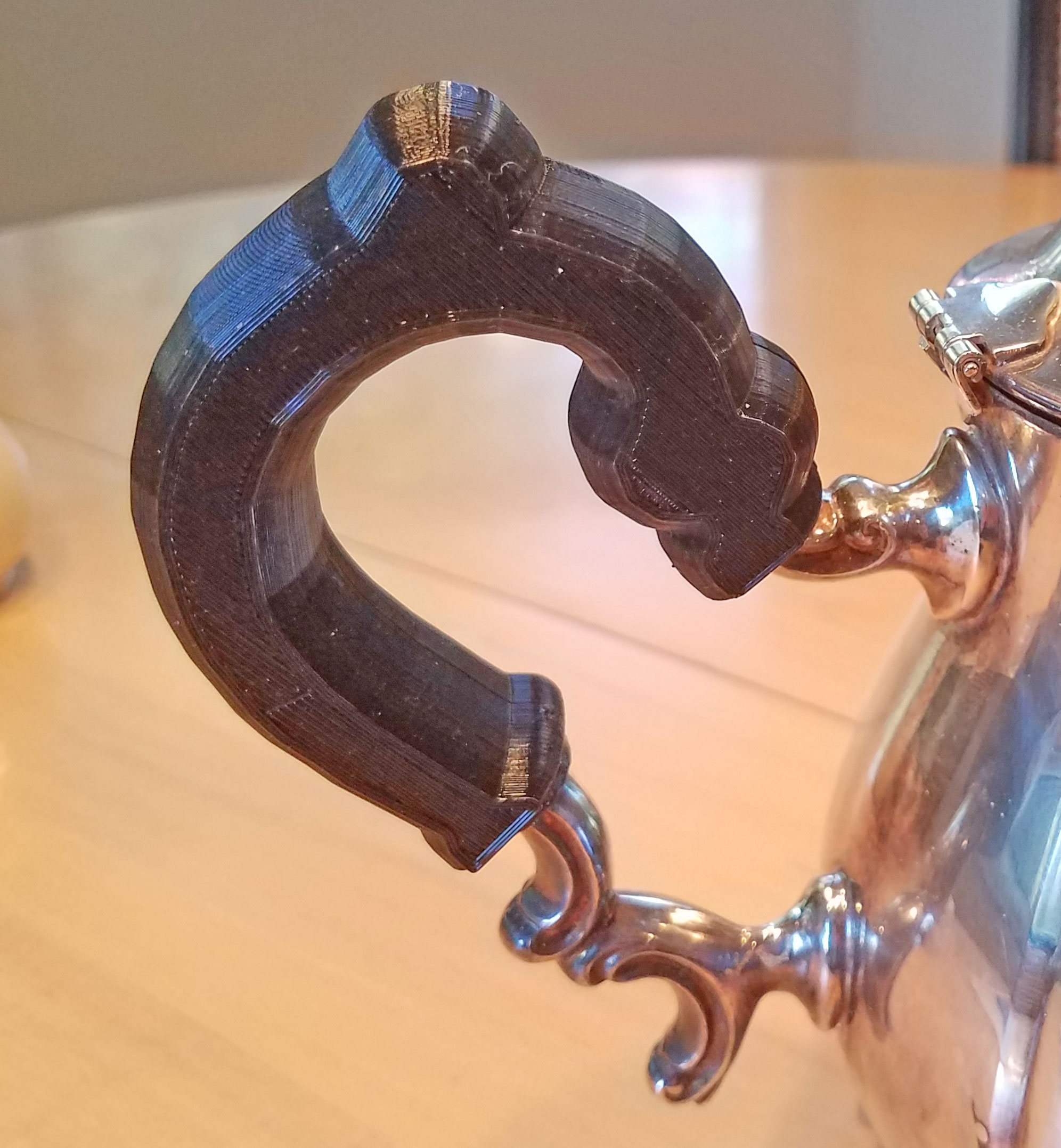
Teapot handle
Rich Altmaier, Nov 17, 2017
I have a teapot where the handle gets too hot to hold! What to do? 3D print a wrap around handle!
The existing handle is a curvy shape and I like to use openscad, which prefers regular geometries, so what to do? There are two technical problems. First is the curvy handle which must become a cutout. Second is the new handle which should be rounded and follow the contours of the existing handle.
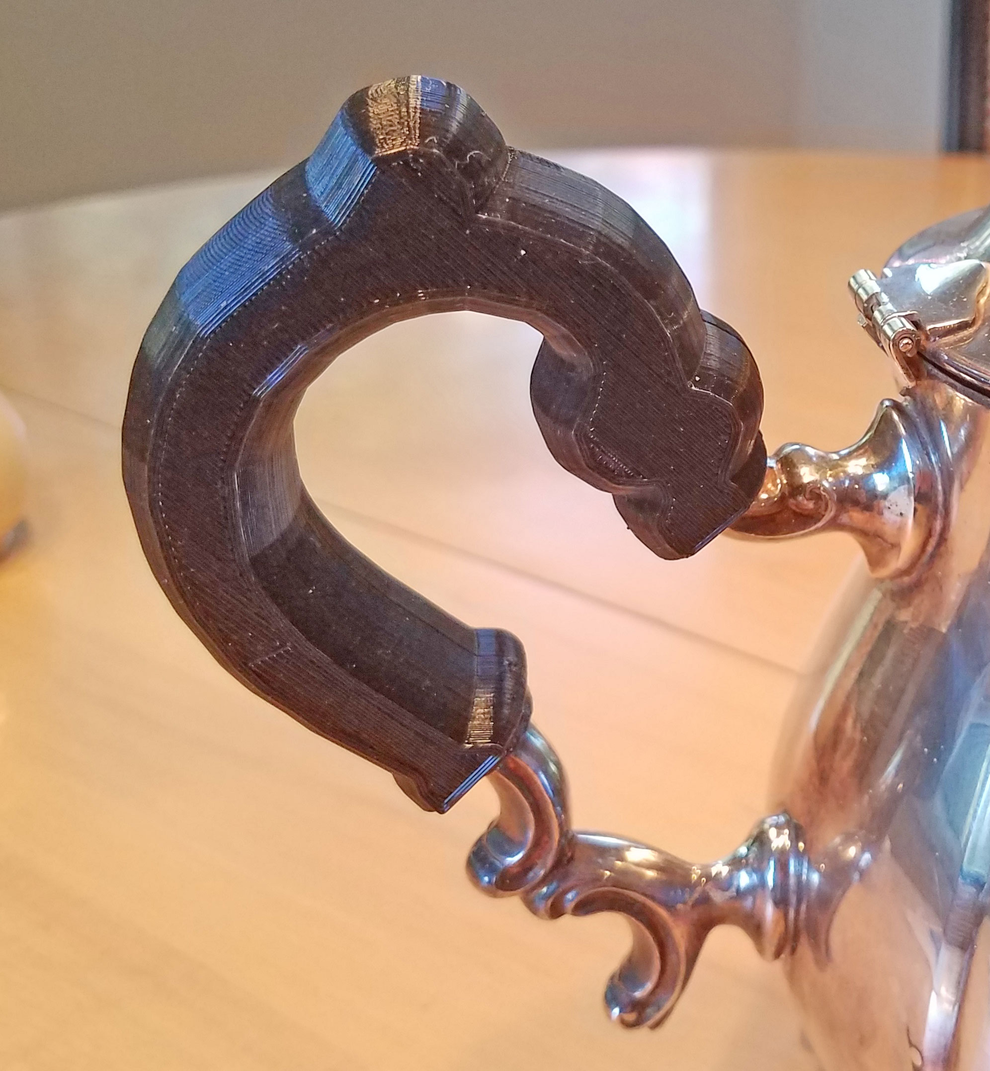
Shown is the existing handle, and what I ended up with.
This Is the Final Result.
Using Openscad to Create a 3D Handle
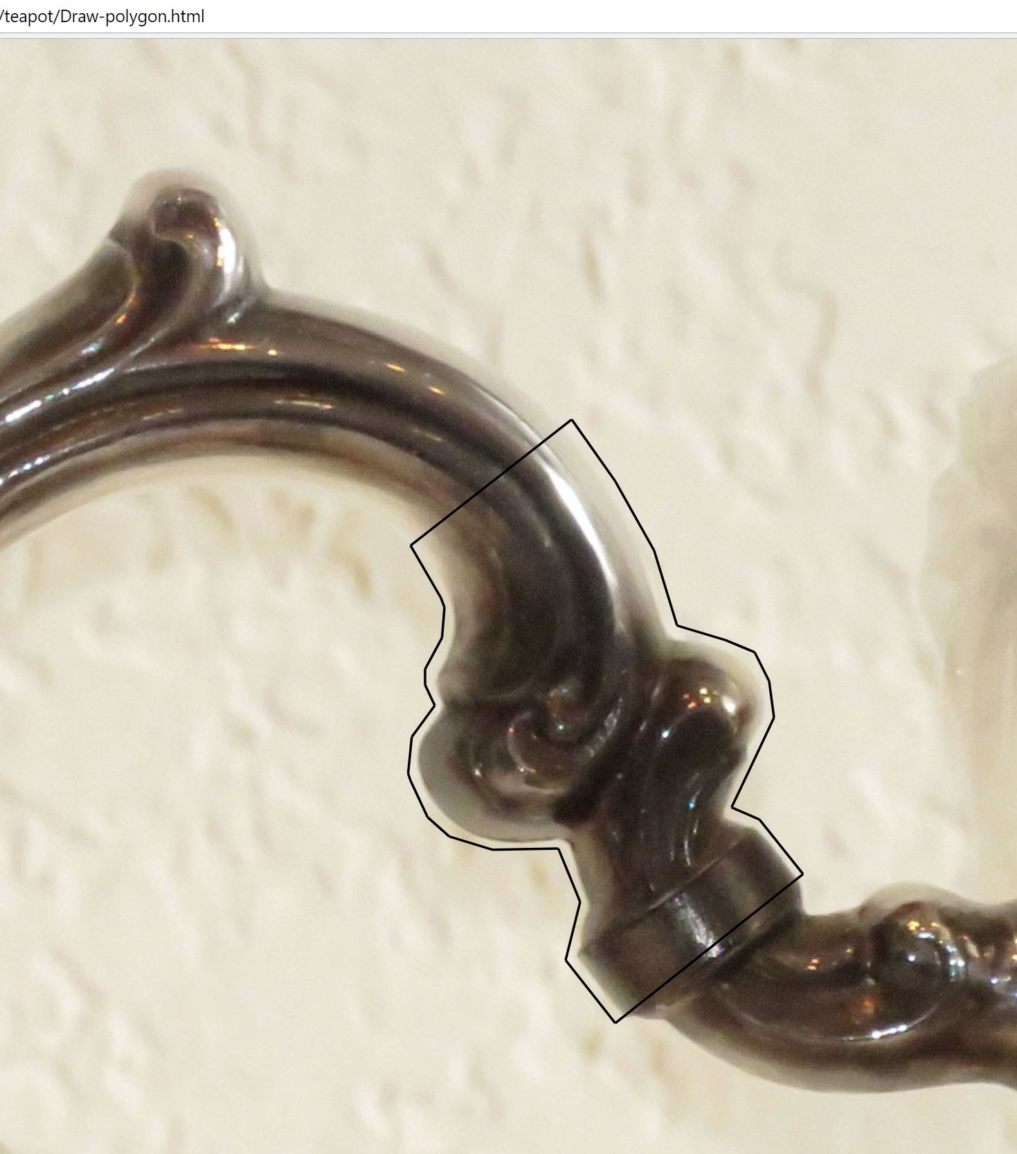
The openscad polygon is a nice way to formulate the existing handle shape for a cutout, as it allows an arbitrary sent of points to describe a curvy shape. The polygon requires a set of datapoints which describe the outline. Thanks to Bryant Howell at Tableau and Behold, I found a javascript utility which can record points and construct a line on top of an arbitrary background image. This enables clicking your way around a shape, while the pixel coordinates are recorded. The coordinates can then be cut and pasted into a spreadsheet.
This utility is in the attached file Draw-polygon.txt. Download and rename it to Draw-polygon.html, then open it in a browser and follow the instructions. The image file should first be resized to about 1500 x 1500 pixels.
Here is an image of the html file where I have clicked around a fragment of the handle to illustrate the process. In the data capture, I had to be careful to stay at the handle boundary, even while the silver reflected the background wall and showed a blurry edging!
Downloads
Obtaining the List of Points Outlining the Handle
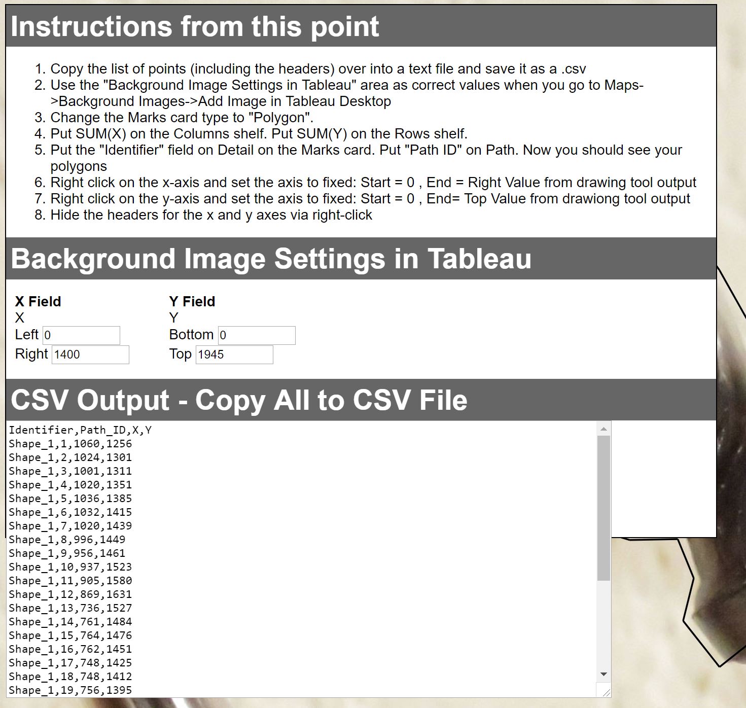
In the polygon capture javascript browser page one finishes by clicking the Output Polygons button, which gives the point list to capture to Excel. Cut and paste the list of points into a .txt file.
Open Data Points in Excel and Chart It
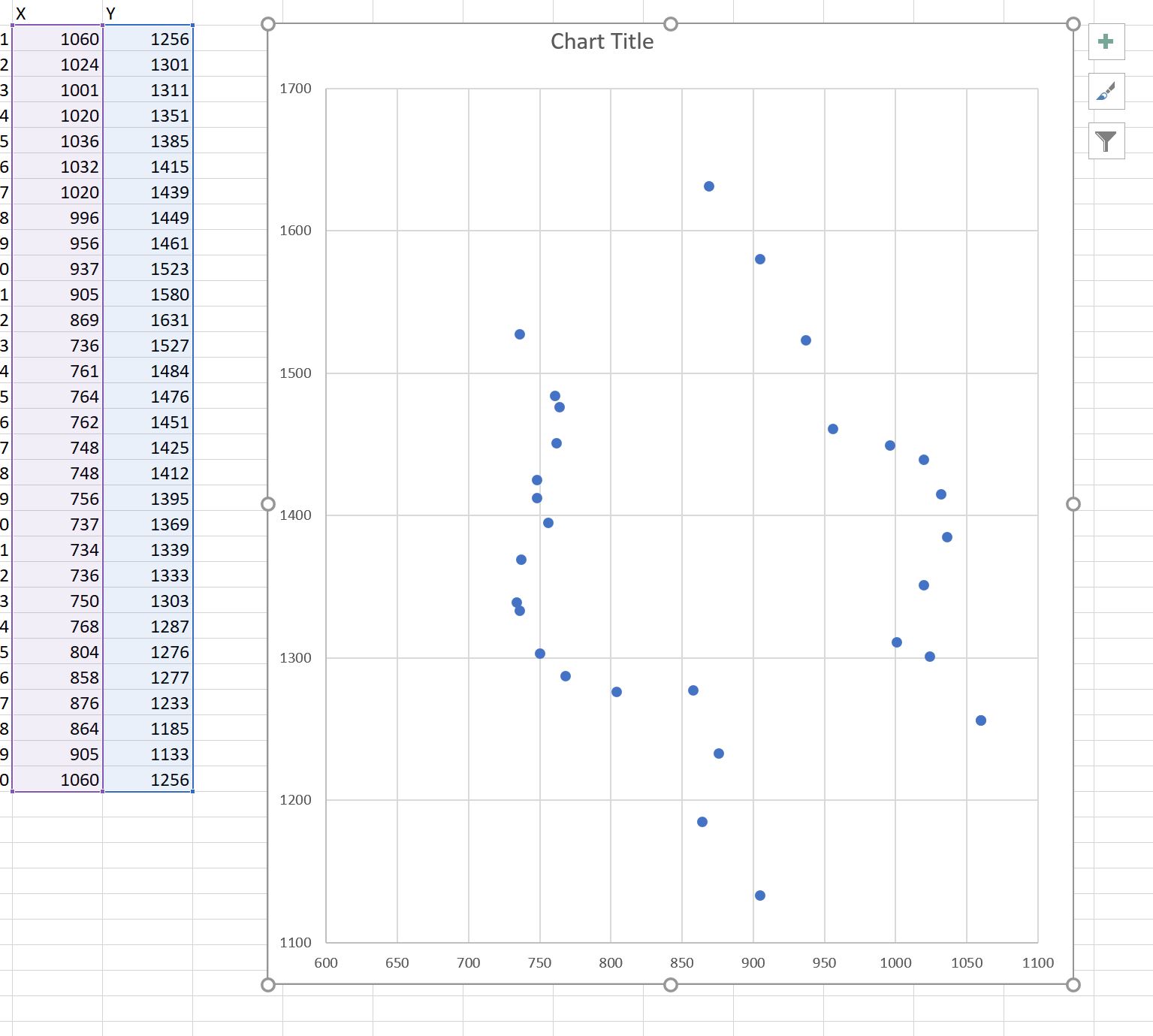
In Excel, open the .txt file and tell Excel it is a “delimited” file, and select comma as delimiter characters.
Now select the two columns of datapoints, and in Excel Insert - Scatter chart. This provides a small chart, showing the specific points captured. Drag the chart taller or narrower until the points look about the same as in the image file overlay!
The above image shows the upper handle first portion, as I digitized earlier.
The next step is to cut out points which are too close together. Openscad’s polygon processing doesn’t like data points too close together, or points which are the same or go backwards. The list of points must show continuous progress around the shape! Above you can see some points nearly on top of each other, so I will delete them from the excel table.
Cleaning Up the Data Points
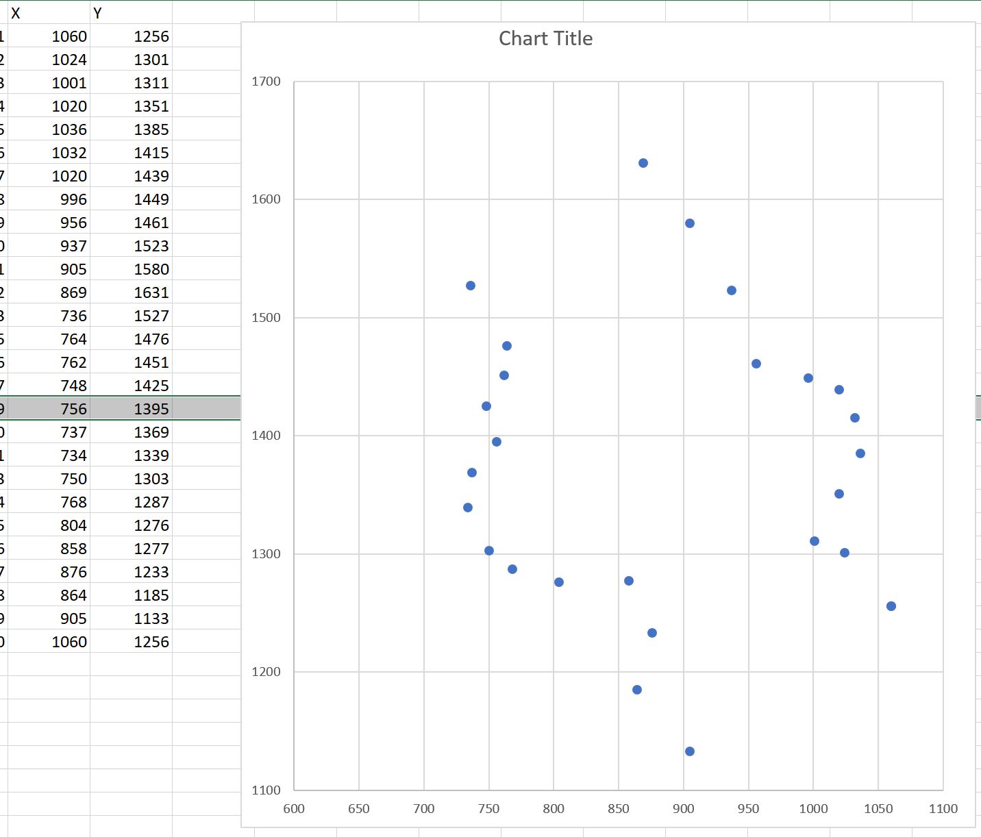
Don't proceed further until you clean up this data! As you delete rows in Excel, the chart updates so you can see what you are doing.
Now this simplified set of datapoints should process without error in openscad!
Creating an Openscad Polygon From the Excel Data
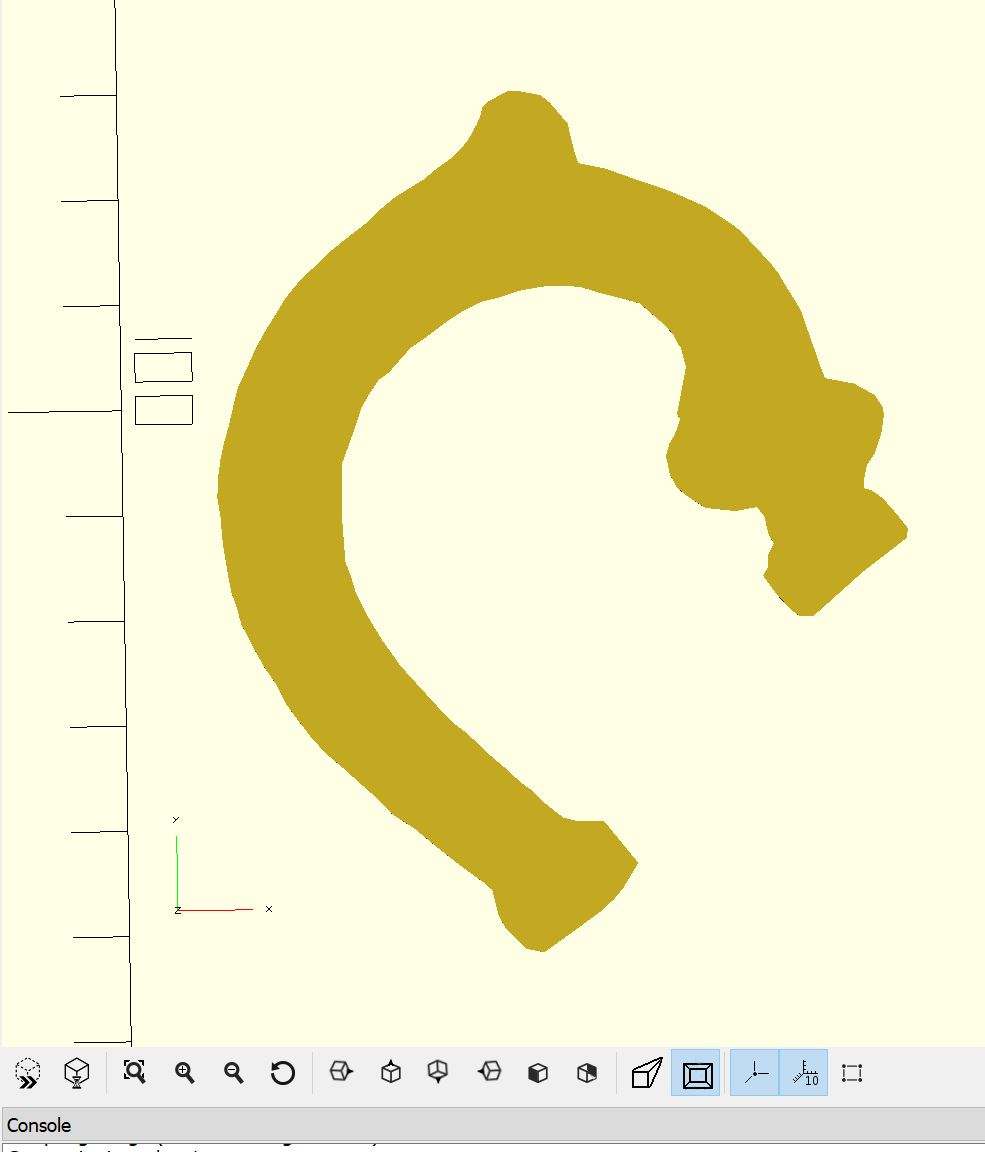
The data points have to be converted into openscad polygon syntax. For this we do an Excel Save-As and select CSV comma delimited file type. This text file needs further editing to put in polygon syntax, where each point must be:
[1060, 1256],
[1024, 1301],
and so on. This text format can be cut and pasted into openscad. Since the data points are in pixel units, we scale them to mm, and plot the polygon:
HandleCutout= [
[1060,1235],
[1062,1248],
[1049,1265],
[1029,1289],
… ];
Scale_tomm = (1845-679)/81.9; //top of tip to lower edge is measured at 81.9mm
ScaleHandleCutout_tomm = HandleCutout / Scale_tomm;
polygon(ScaleHandleCutout_tomm);
And we get this polygon shape, which is 2D, a flat shape.
A 3D Handle Shape
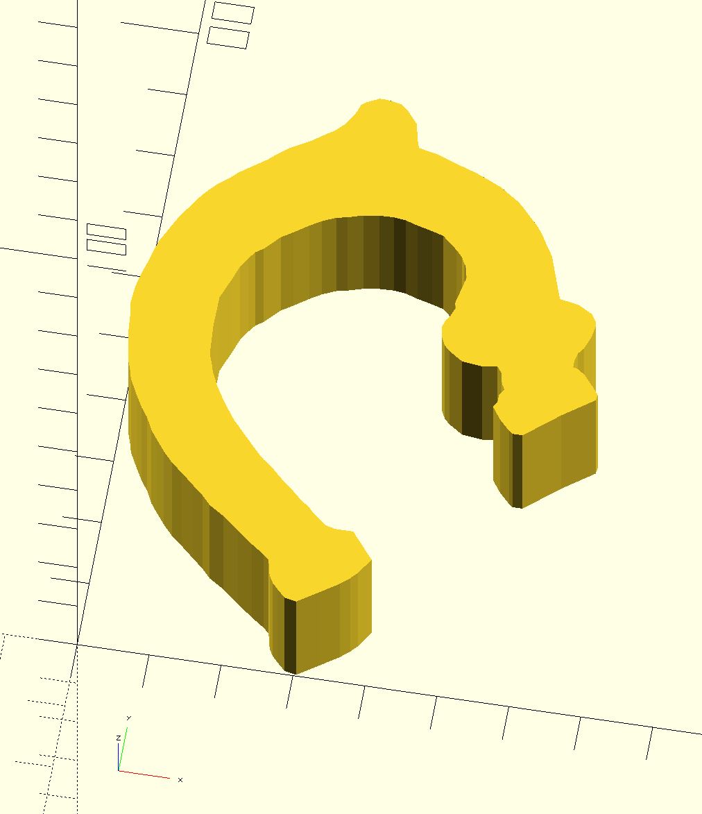
A simple linear_extrude,
linear_extrude(height=19.0 )
polygon(ScaleHandleCutout_tomm);
gives us a cutout 3D shape where our teapot handle will reside, inside of the handle shell we are building toward.
Imagine the Inner Cutout Where the Teapot Handle Will Hide Inside the New Shell
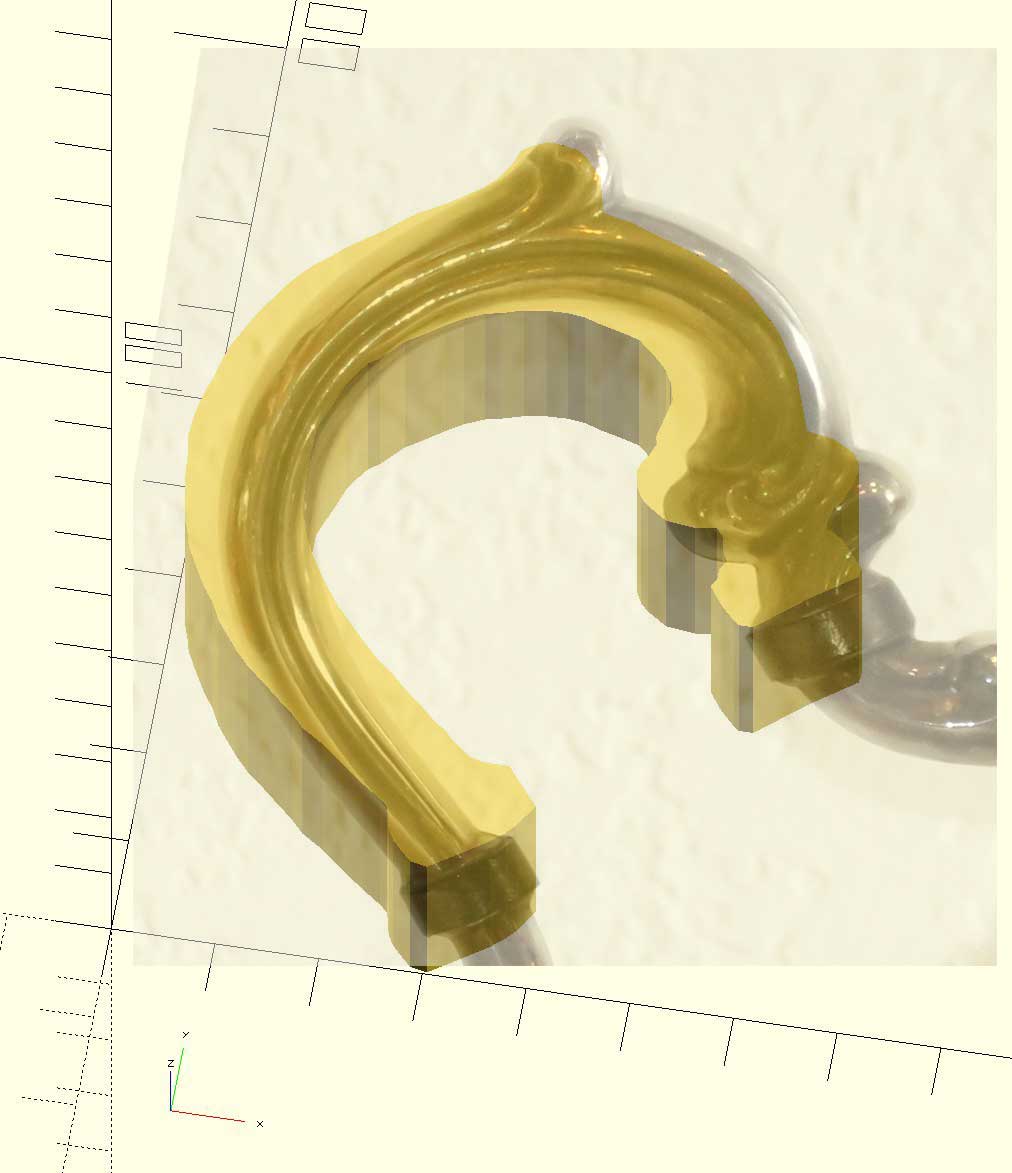
And with my limited Photoshop skills, please imagine the teapot handle inside this cutout, inside of the wraparound handle.
But as you can see, the curvature of the handle is not captured by the linear_extrude, which creates a rectangular 3D shape.
Getting to a Curved Handle in Two Dimensions
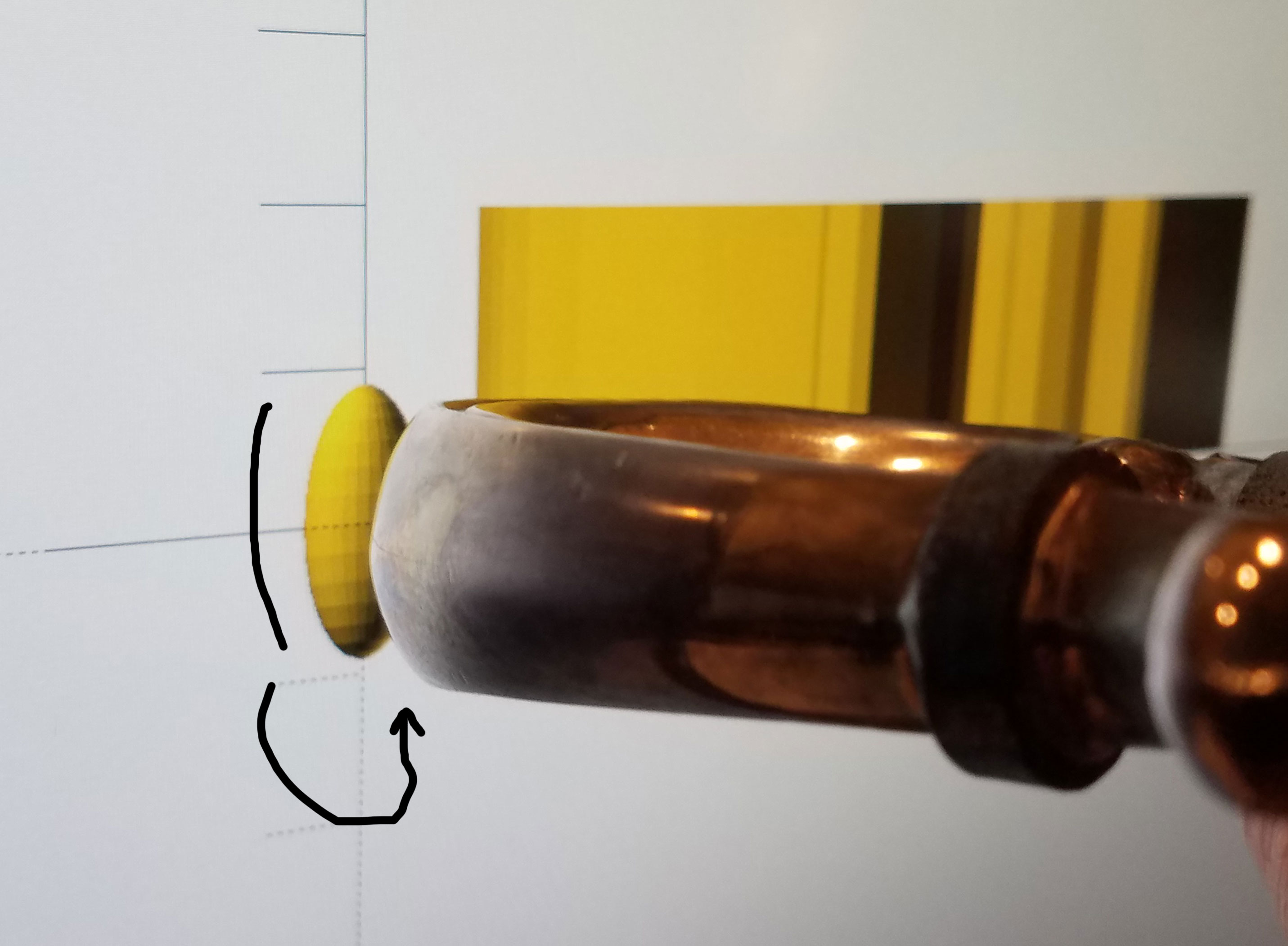
The method to create a 3D shape, which curves in the Z-dimension, is to use minkowski() in openscad. Minkowski() will add curvature to square corners. Minkowski is driven by a distorted sphere.
First I create an elongated sphere where the curve is close to the Z-curvature of the handle, as shown here.
Openscad Minkowski() Starts to Apply Curvature!
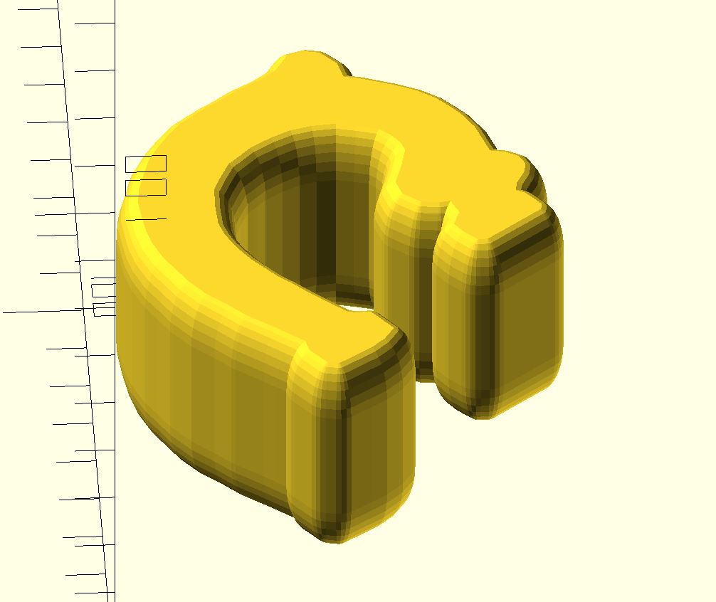
Applying minkowski() with the sphere to the linear_extrude gives us:
minkowski() {
linear_extrude(height=20.0) polygon(HCtomm);
scale([0.45, 0.45, 1.0]) sphere(r=9);
}
But this 3D shape it is too fat and tall, as minkowski adds the radius of the sphere to both height and thickness while rounding, in effect wrapping the curvature onto the linear_extrude!
Controlling the Radial Thickness of the Handle
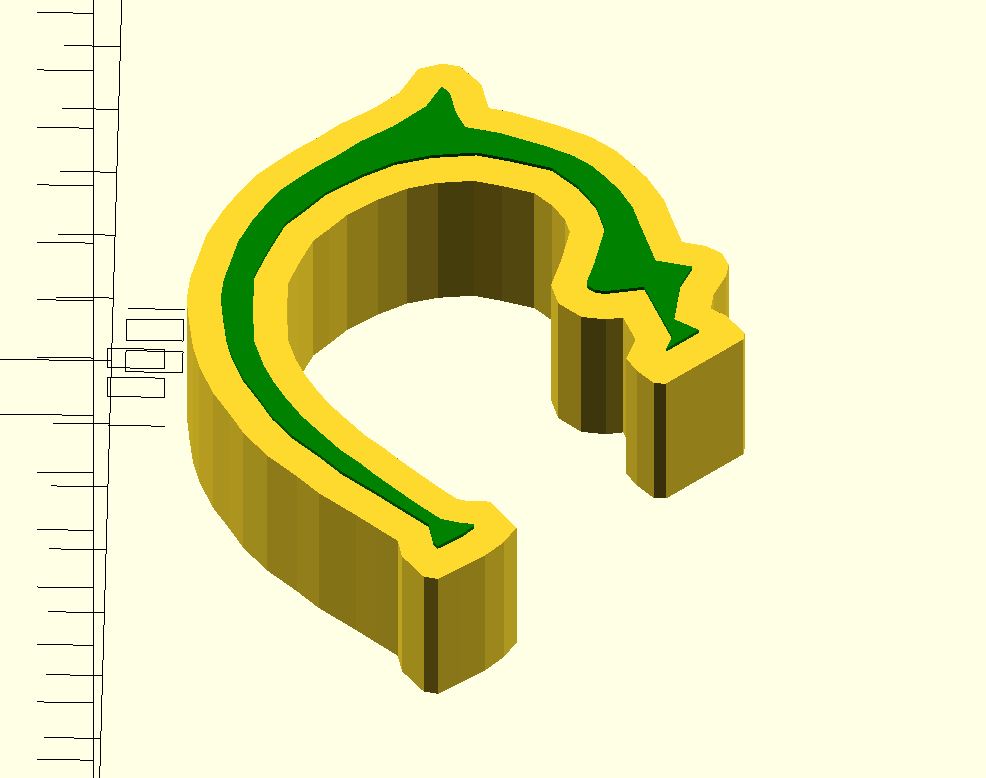
We have to fix the extra fatness in two dimensions:
a) width of the handle, composed of extrude amount + the minkowski sphere radius added to each side,
and b) radial thickness of the handle, composed of the polygon outline itself plus the minkowski sphere radius on each side. It is easy to change the extrusion height! But we must “narrow” the polygon while retaining its 2D dimensional outline, so a shrink won’t work! Openscad’s offset() of a polygon is great for this, shown in green, above the linear_extrude.
linear_extrude(height=20)
polygon(HCtomm);
translate([0,0,22])
color("green")
offset(delta=-4) polygon(HCtomm);
Finally a Rounded Handle Shape
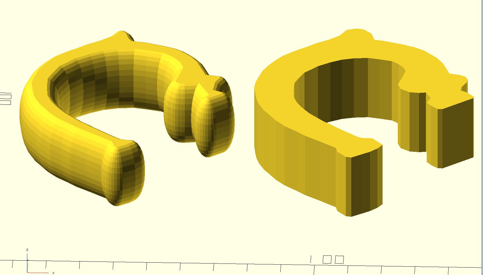
The offset() green polygon is thinned out, allowing the minkowski to fatten it back up again! Apply minkowski to the shorter linear_extrude of the “thin polygon”, to get as shown. This is now our openscad model of the original handle! The radial curvature is controlled by the captured datapoints formed into a polygon. The radial thickness is controlled by thinning the polygon. Width is controlled by the extrude height. And the curve/cut-through of the handle is controlled by the sphere shape applied with minkowski.
translate([80,0,0])
linear_extrude(height=20)
polygon(HCtomm);
minkowski() {
linear_extrude(height=2.0)
offset(delta=-4)
polygon(HCtomm);
scale([0.45, 0.45, 1.0]) sphere(r=9);
}
Orginal Handle Shape
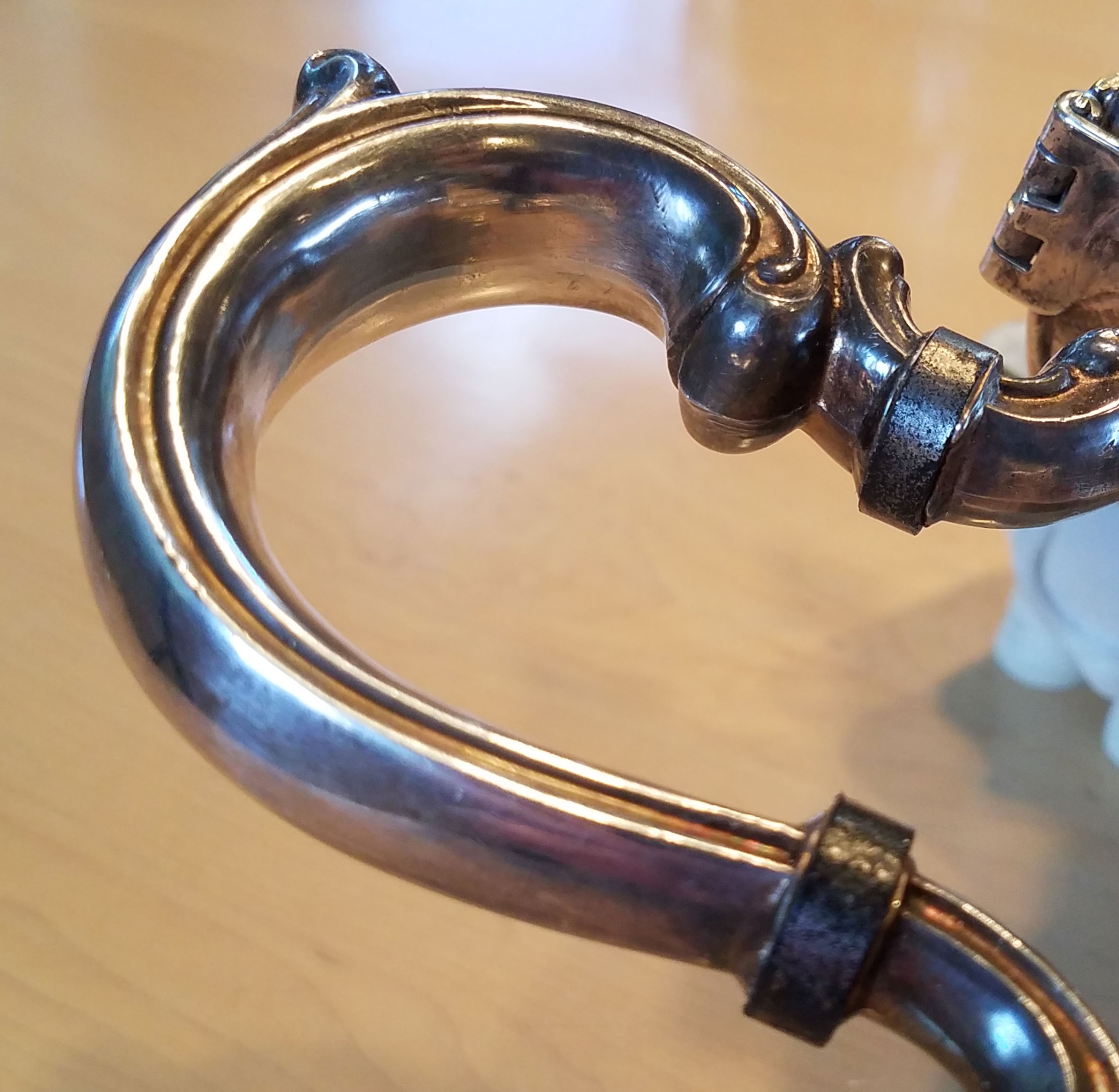
Remember this is the handle itself, to be cut out of the new outer shell handle.
Creating the Outer Shell Handle
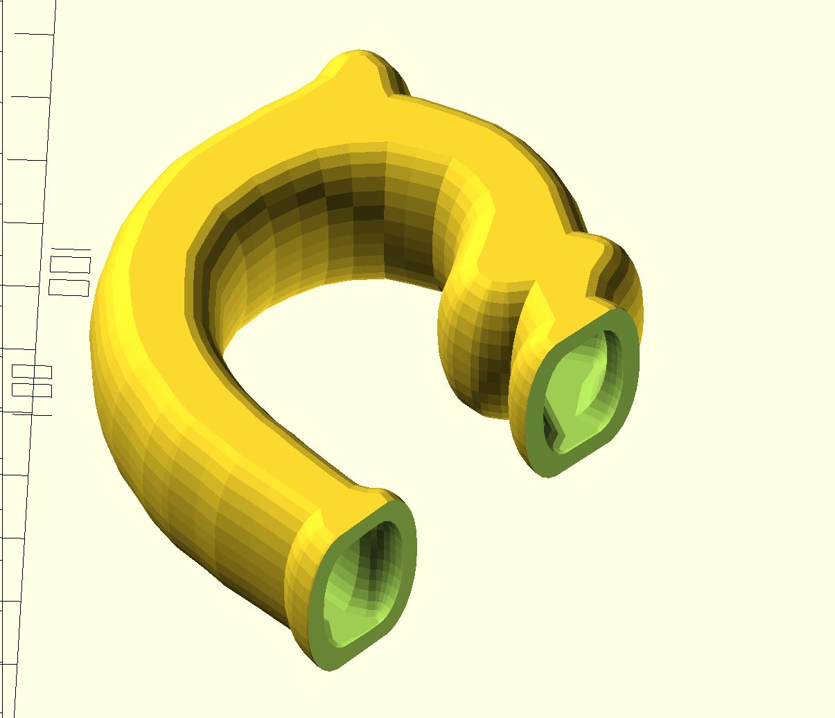
To create the outer shell, I increase the sphere by 3mm and reduce the thinness of the “thin polygon” less. This makes the new outer handle shape. Then cut away the interior, and trim off the ends, and we have this.
difference() {
minkowski() { //outer shell
linear_extrude(height=2.0)
offset(delta=-3) polygon(HCtomm);
scale([0.45, 0.45, 1.0]) sphere(r=12); }
minkowski() { //inner shape, cutout
linear_extrude(height=2.0)
offset(delta=-4) polygon(HCtomm);
scale([0.45, 0.45, 1.0]) sphere(r=9); }
//look at inside
translate([0,5,-20]) cube(60);
translate([0,60, 0]) cube(80);
}
See the Interior Walls
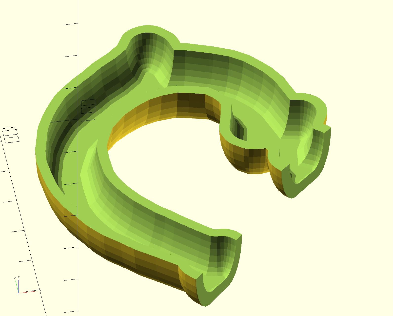
Slicing the handle in half, so we can see the interior.
Print in PLA Black
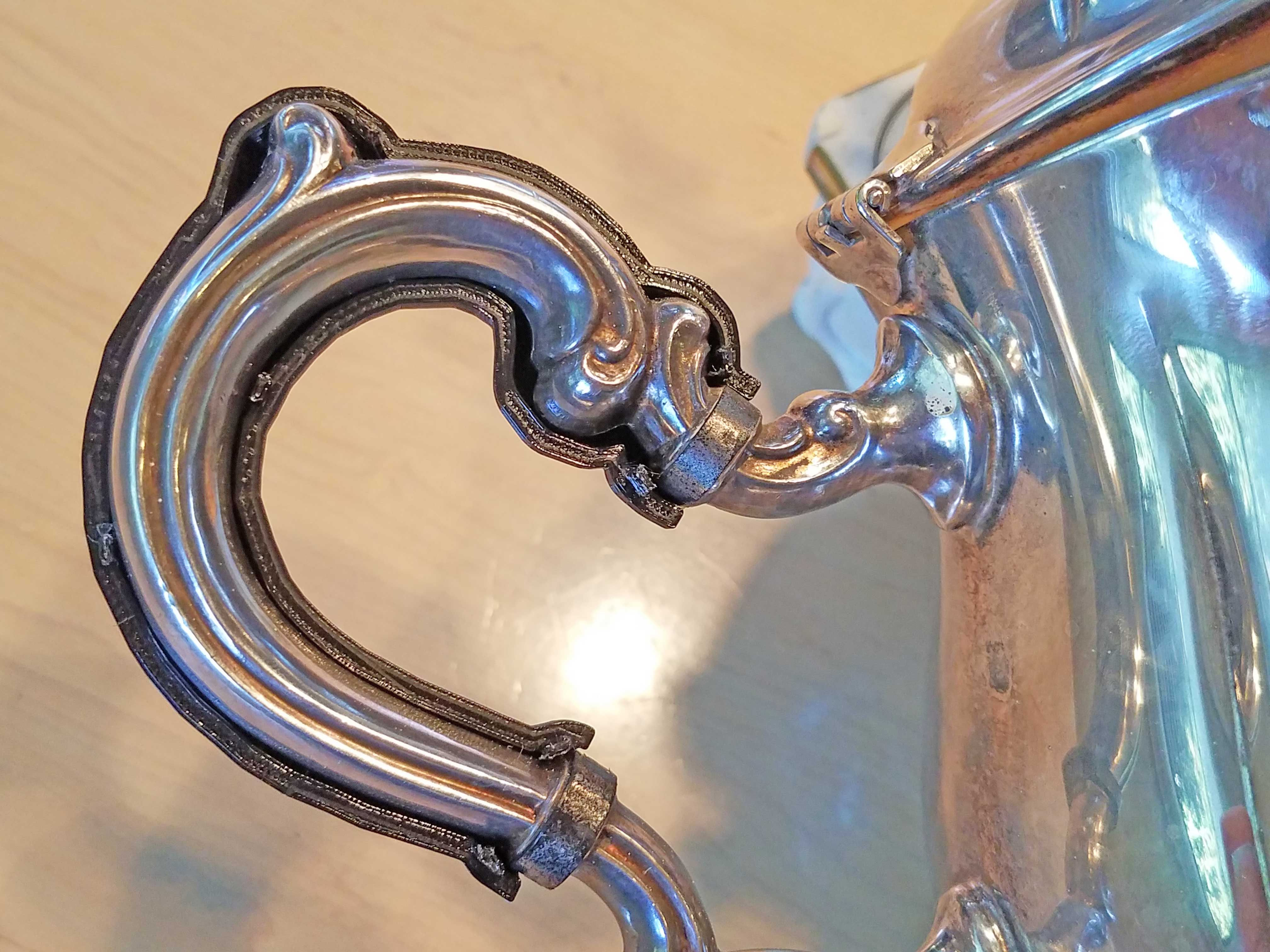
And I'm pretty happy with the fit around the handle!
Snapping the Two Halves Together
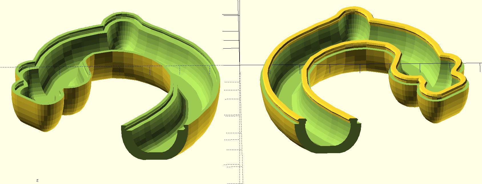
To join the two halves together, I used minkowski on the 2D polygon with a circle, using the same dimensions as the sphere, to create a polygon exactly fitting the middle cut of the handle. Then adjust this polygon larger and smaller to cut out a rim outlining the handle cut. Then use one such rim as a standoff, and the second such rim with a small sphere minkowski to create a snap ring joint. The rim pair goes on top of one half, and cuts out of the other half, and the two snap together! See the function RimSnap2() in the attached file.
Cup of Tea, Anyone?
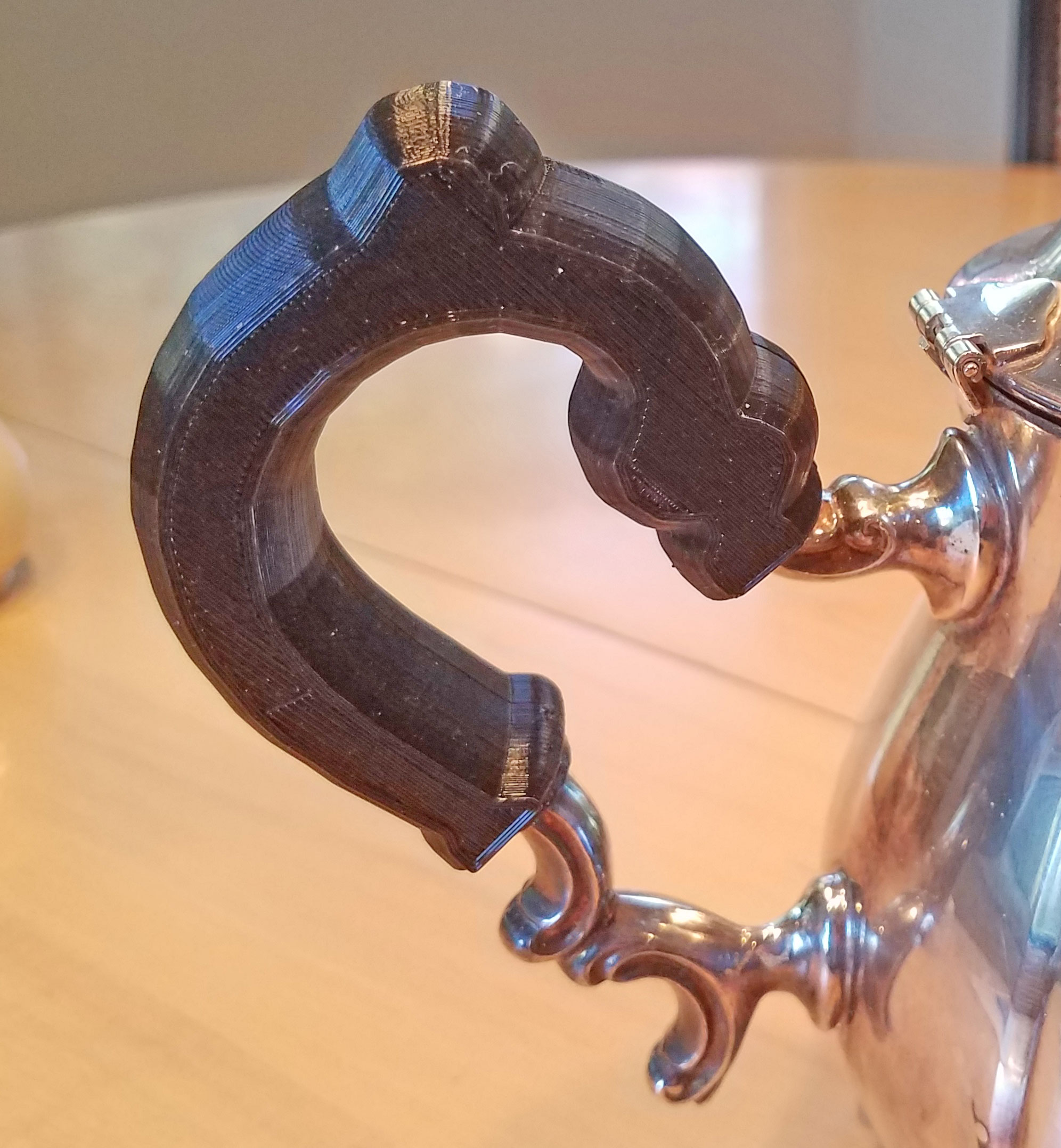
The scad file is attached. I attempted to parameterize basic handle dimensions.
And I included the examples shown above.