3D Printing a Bracket for the Front Light on My Bike With Fushion360
by Kevr102 in Workshop > 3D Printing
474 Views, 2 Favorites, 0 Comments
3D Printing a Bracket for the Front Light on My Bike With Fushion360


This Instructable is about showing you how I design and 3D Print a bracket for the front light on my bicycle.
The original holder just disintegrated and was only held on to the bars with a rubber band, and after holding the light between my teeth for a 15 minute ride home I needed a bracket sharpish.
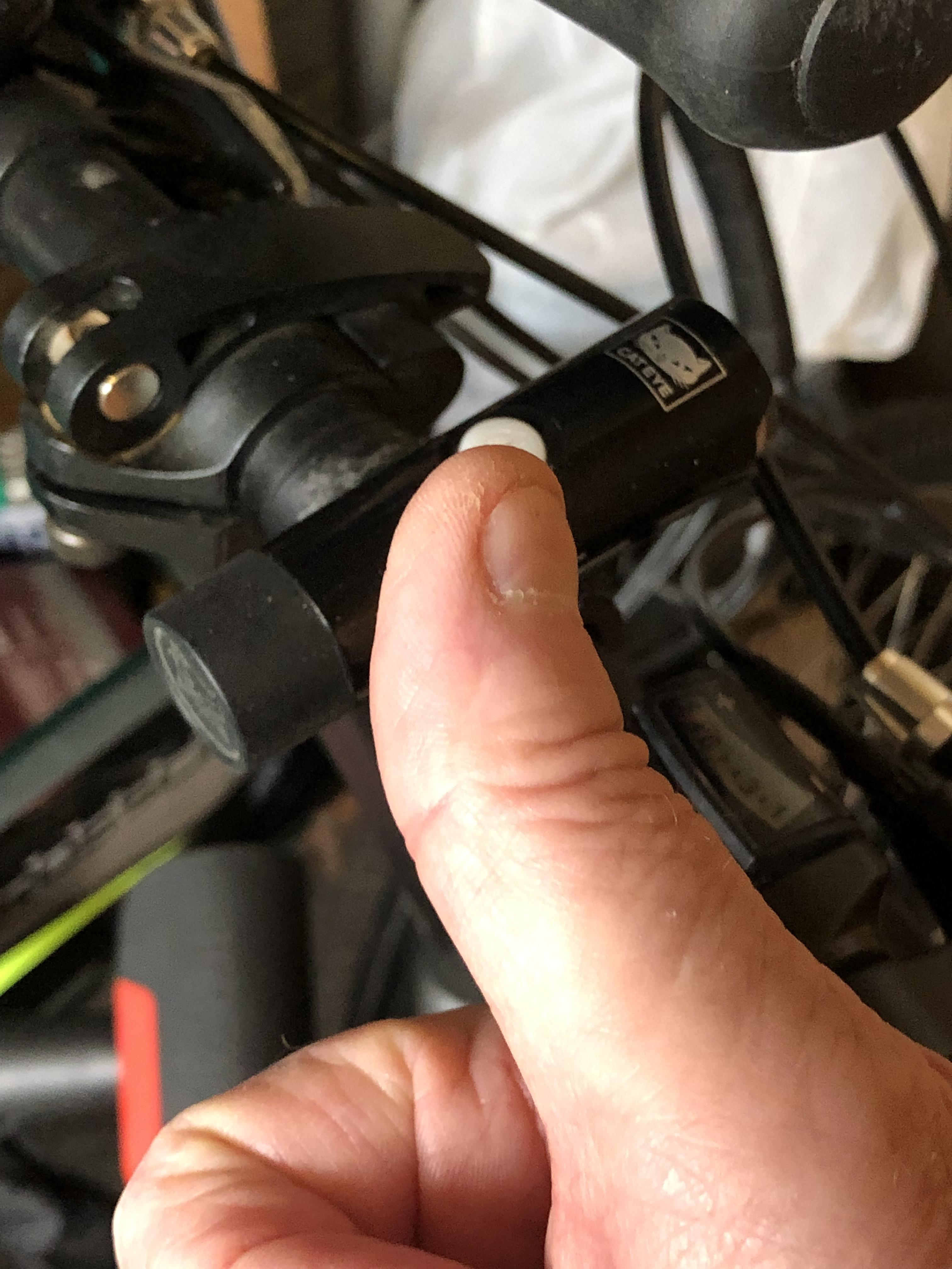
I want the bracket to be strong, Ideally a push fit to the handle bar, also must be easily removeable just in case the light fingered brigade are about.
I will be using Fusion360 for the design and a Creality CR-10 3D Printer with black PLA for this bracket.
Today is the 27.06.2021 and I need it for tonight so speed is of the essence:)
Supplies
Fusion360
3D printer (Creality CR-10)
1.75 Black PLA
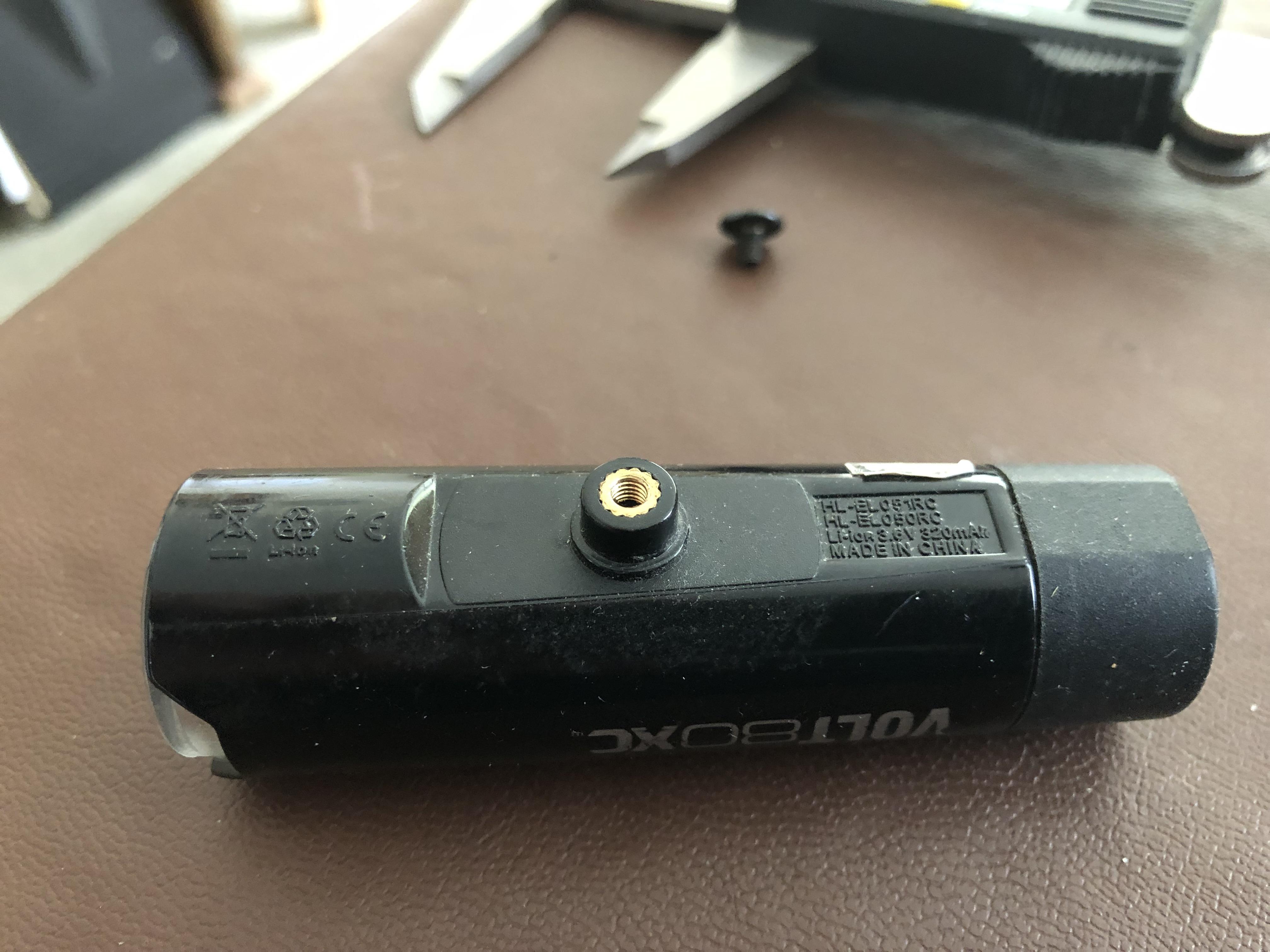
Vernier gauge
Initial Design of the Light Bracket Using Fusion 360

The first thing we need is the diameter of the handle bar, this worked out at 22.53mm but it's tapered so I am opting for a snug fit push on/pull off style bracket.
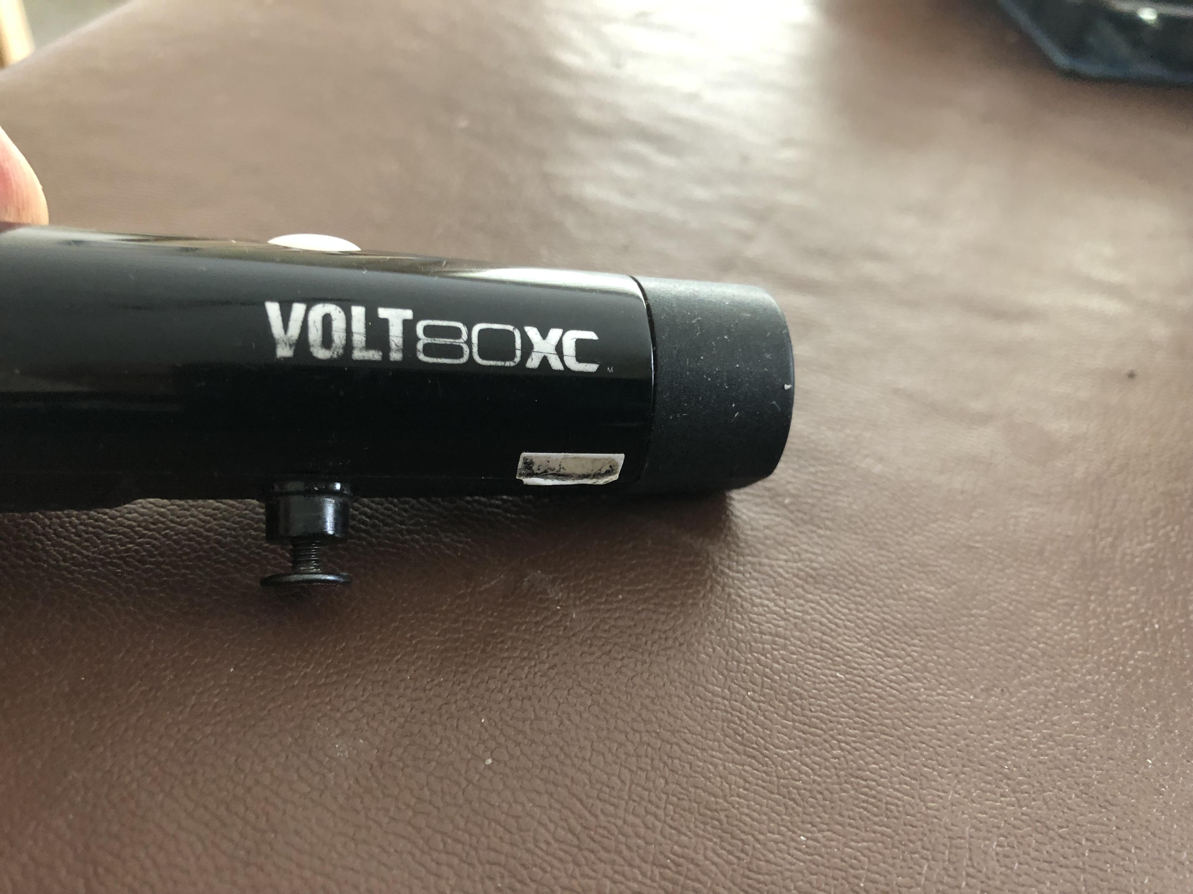
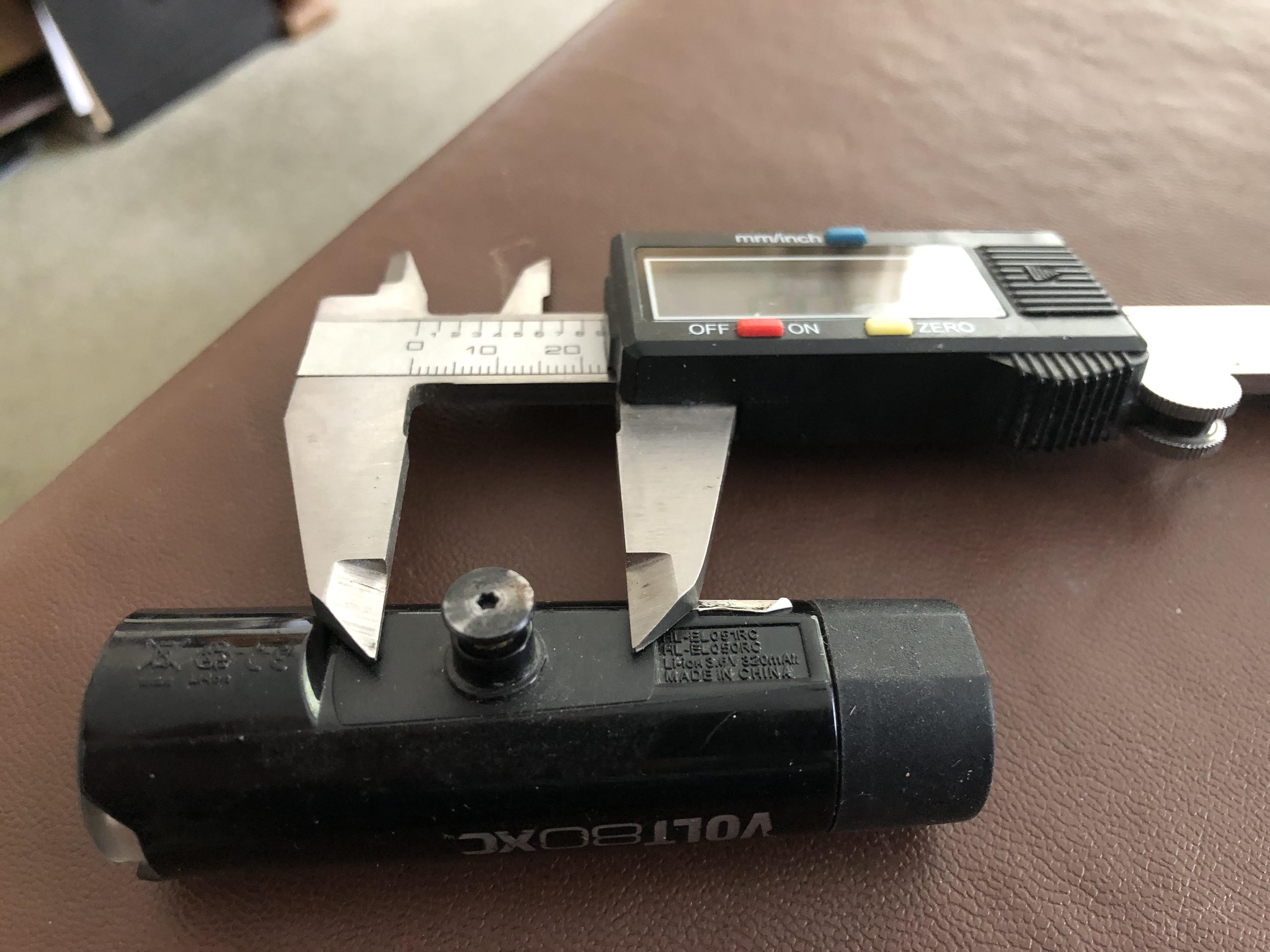
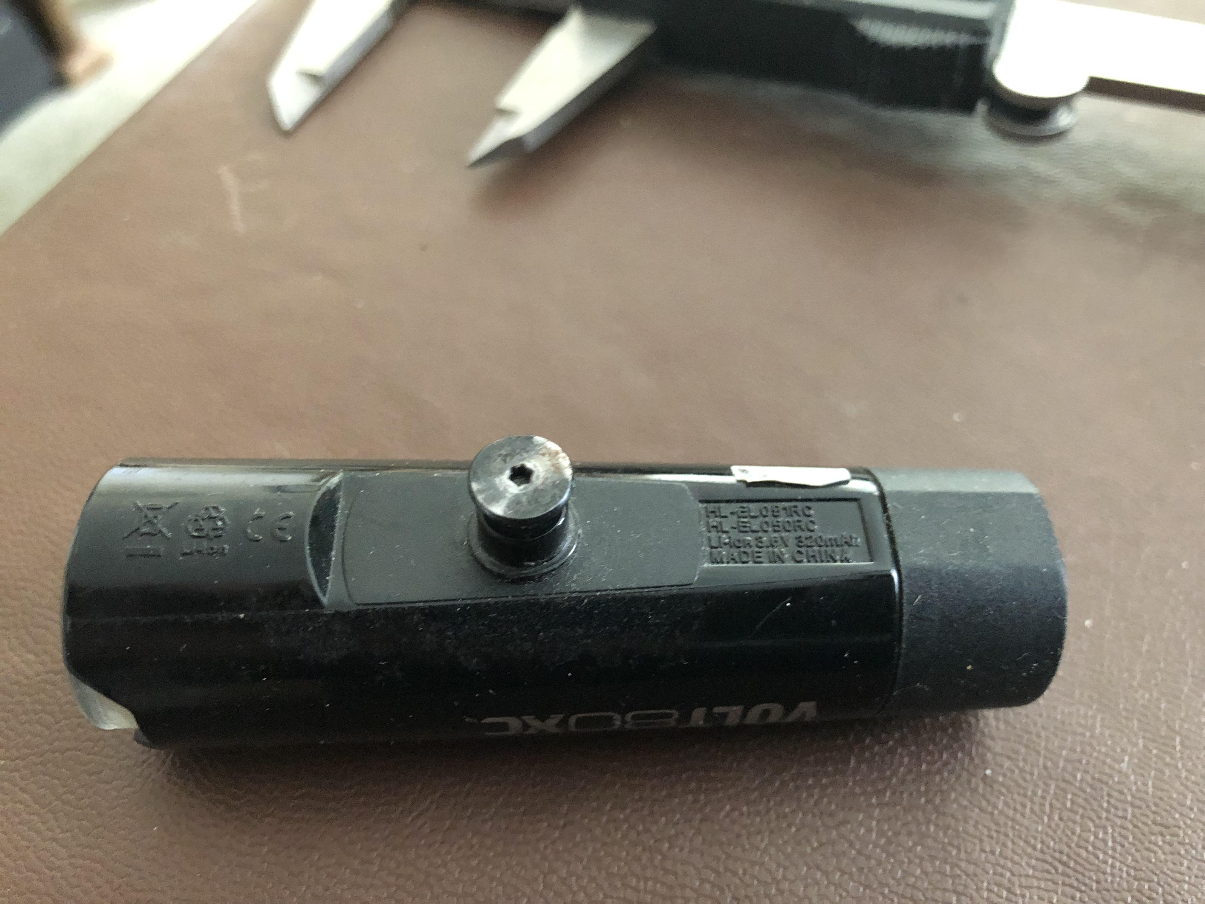
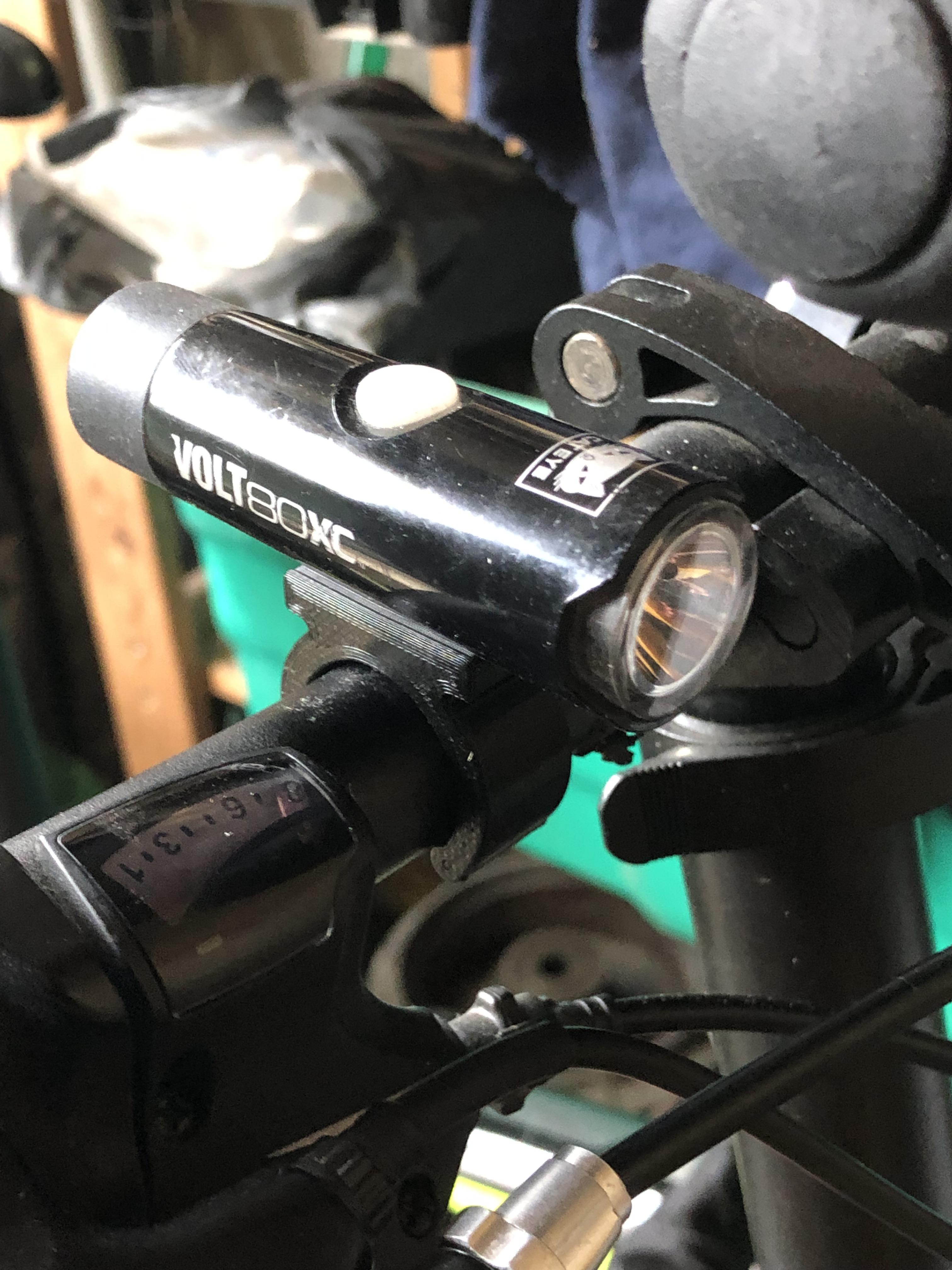
Looking at the bottom of the light see's a flat area of 28mm in length with width 12mm to the front of the light tapering to 10mm to the rear.
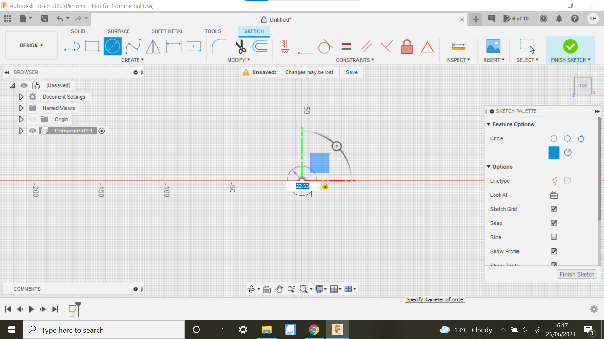
The first process with Fusion 360 is to start a new component and create sketch using the Top plane.
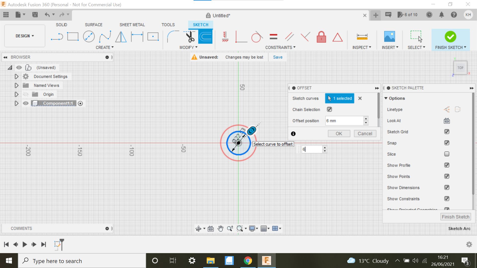
We sketch a centre circle @ 22.53 and then offset this outwards by 4mm.
The next part is a bit of a guess, I want the bracket to snap into position so it needs to be a tight fit and don't want to force on so much that it breaks it.
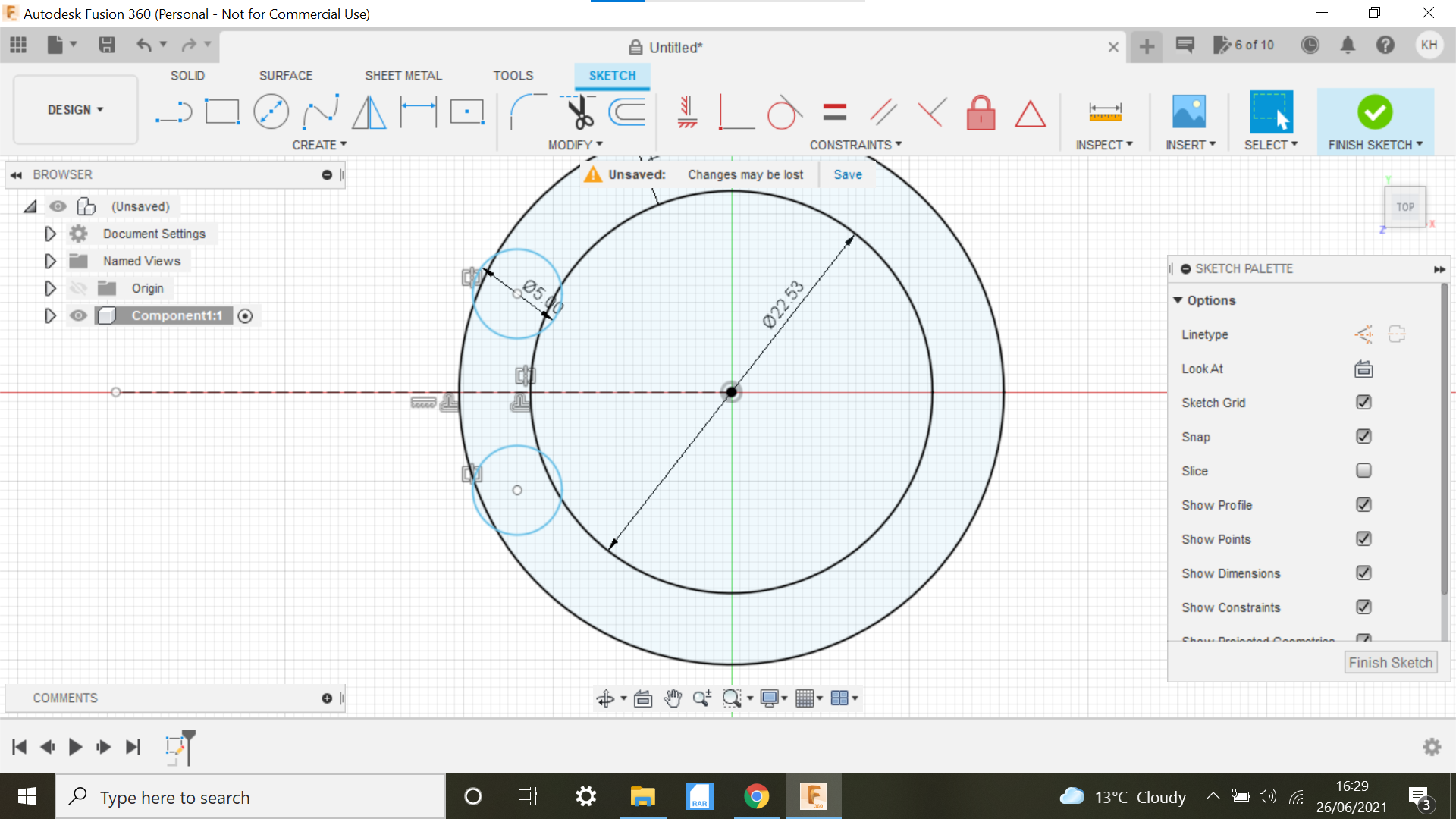
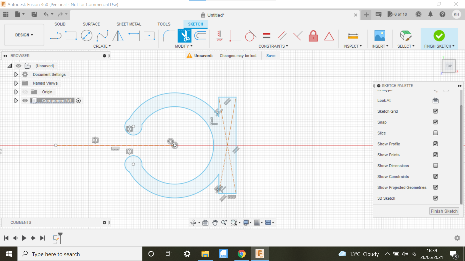
Take a look at the screen shot for the next part, sketch a 5mm centre circle and position it somewhere where you can see it opening up the bracket enough for it to snap onto the handle bar.
Sketch a line through the circle and make it a construction line, then mirror the 5mm circle using the construction line for our centre.
Next we create a centre square @ 28mm x 5mm on the opposite side to the 2 x 5mm circles, this will be for the light to sit on.
Trim any unwanted lines with the Trim tool
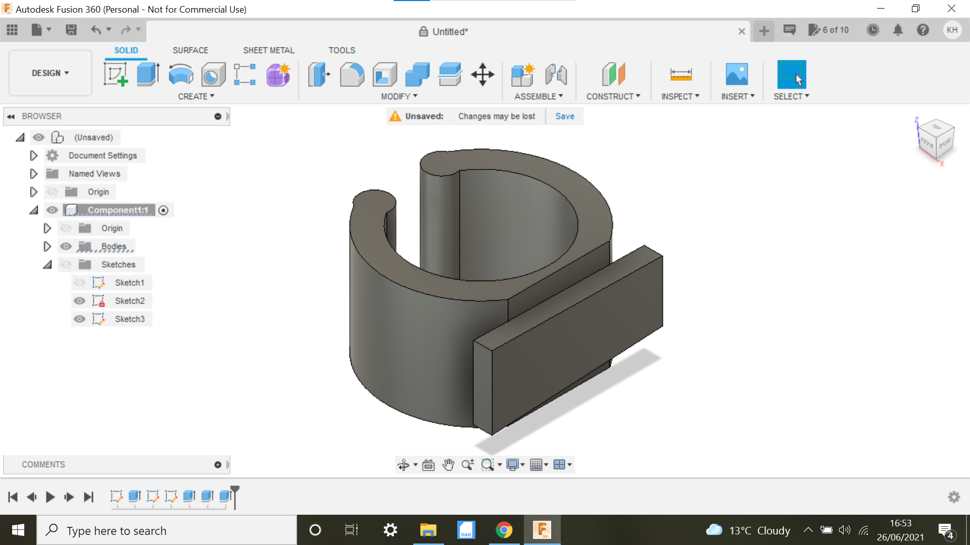
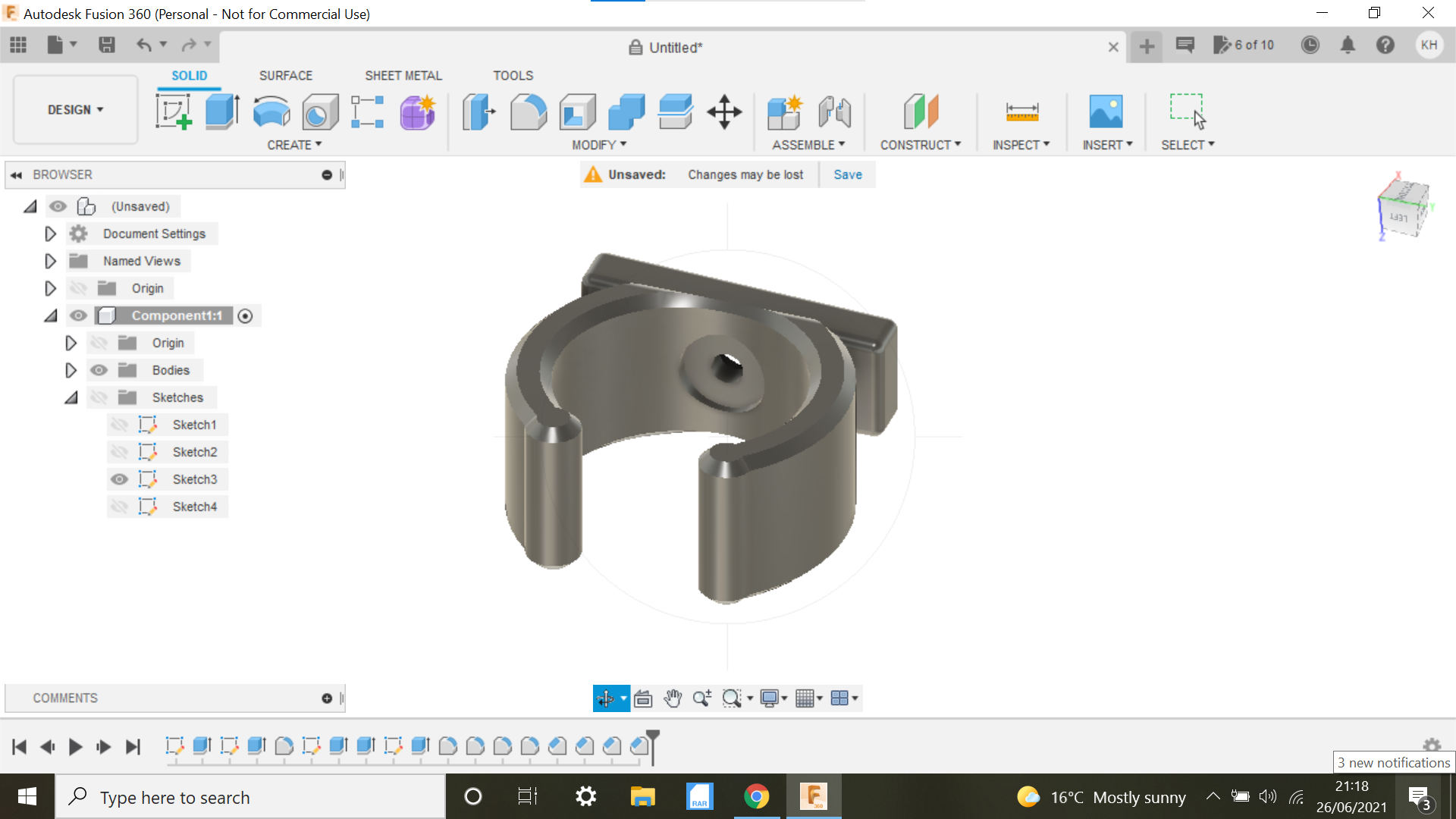
When the bracket is extruded it will make more sense.
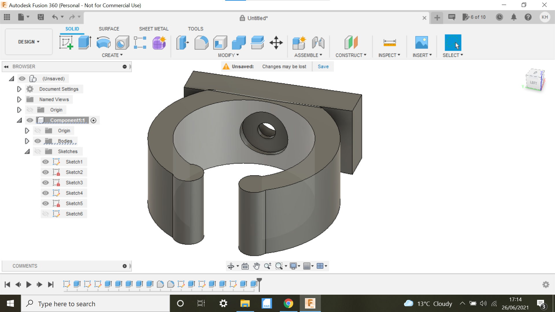
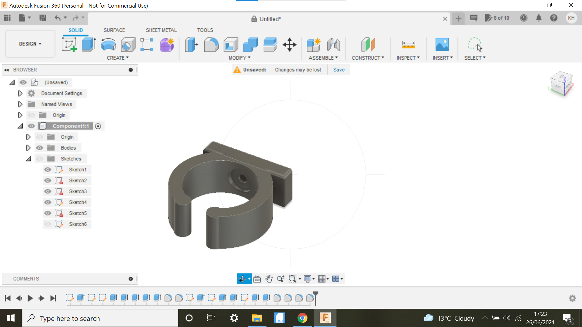
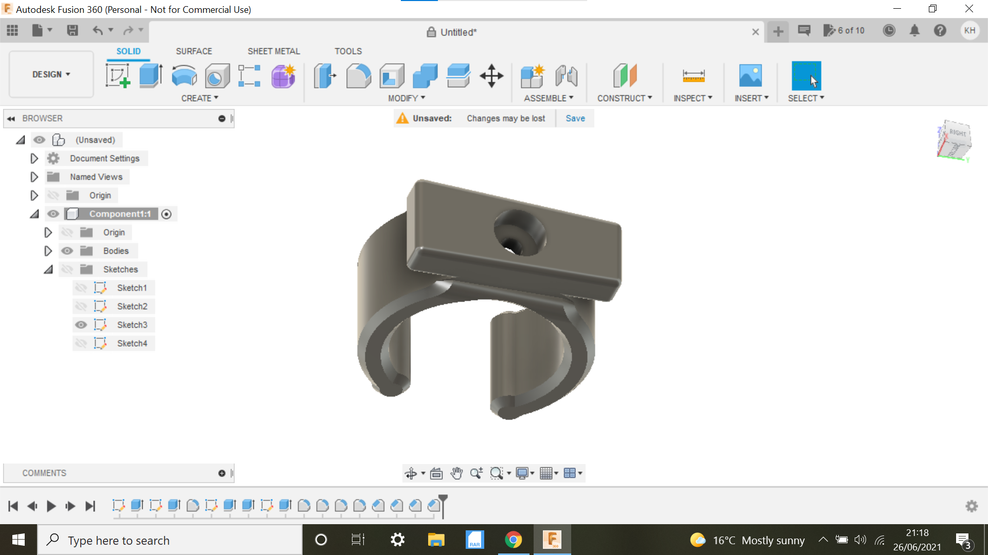
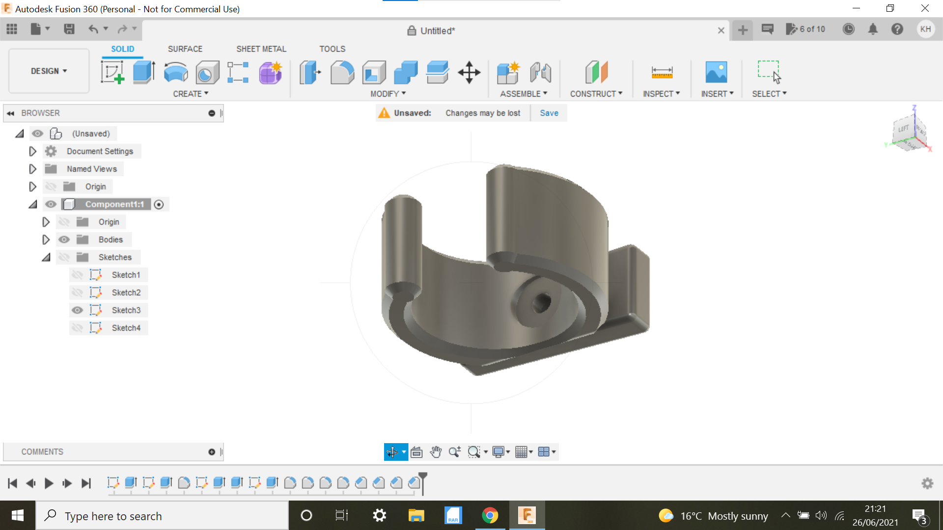
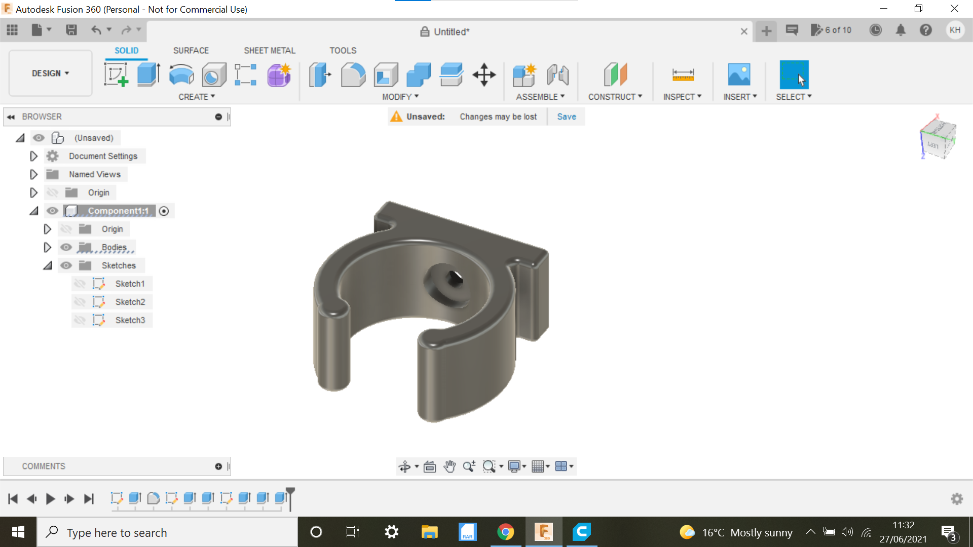
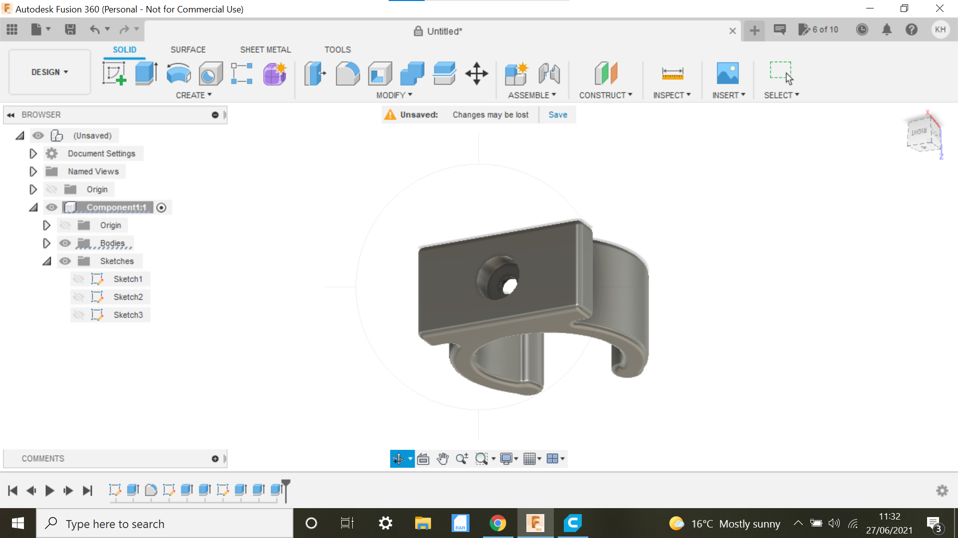
With the bracket extruded to 15mm we can then see what the bracket looks like and what adjustments if any need to be made.
The first thing I did was to mimic the taper on the light to make it the same on the bracket, the taper was 12mm to 10mm.
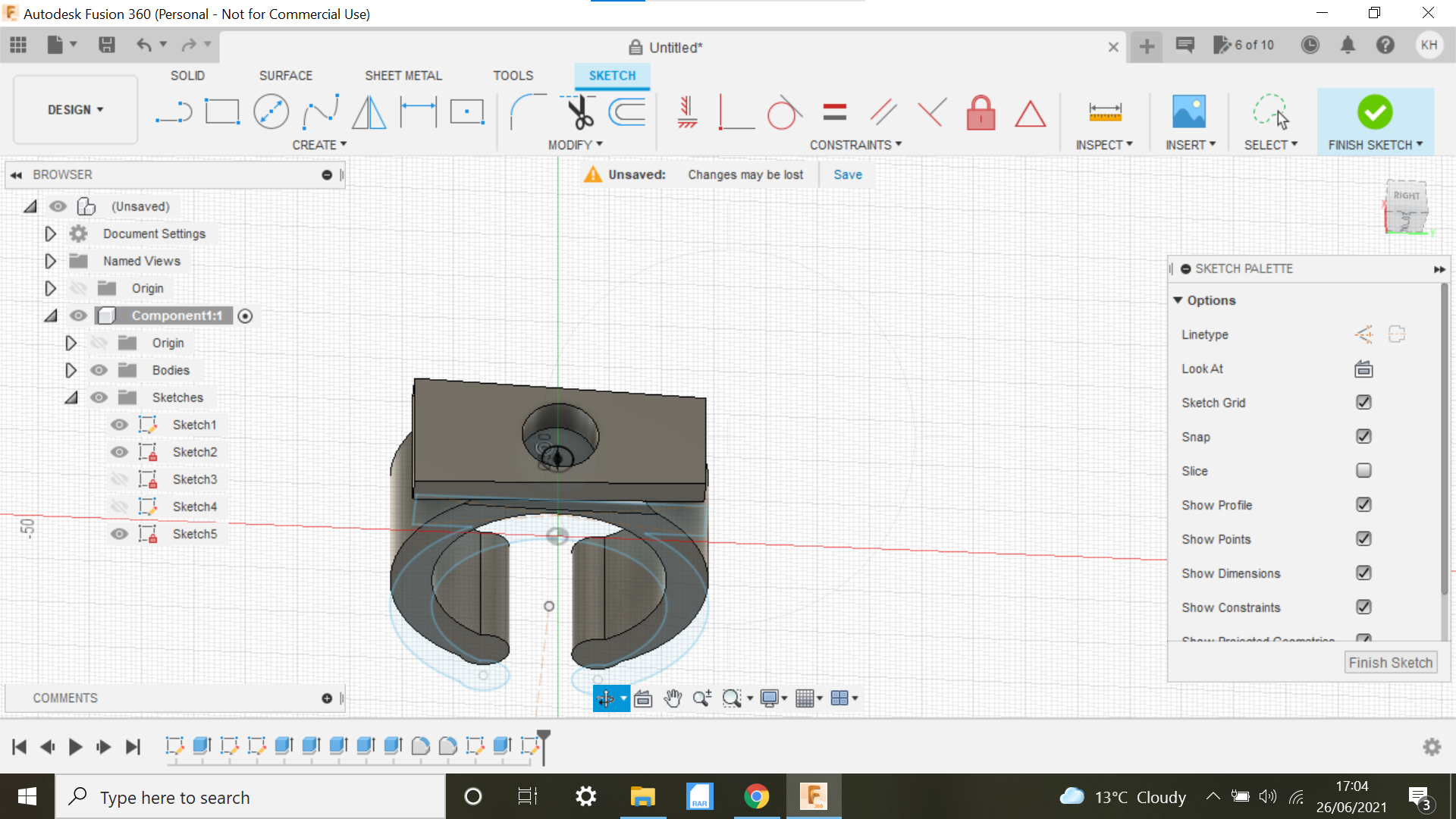
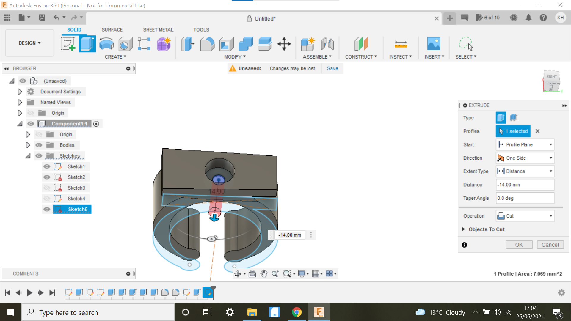
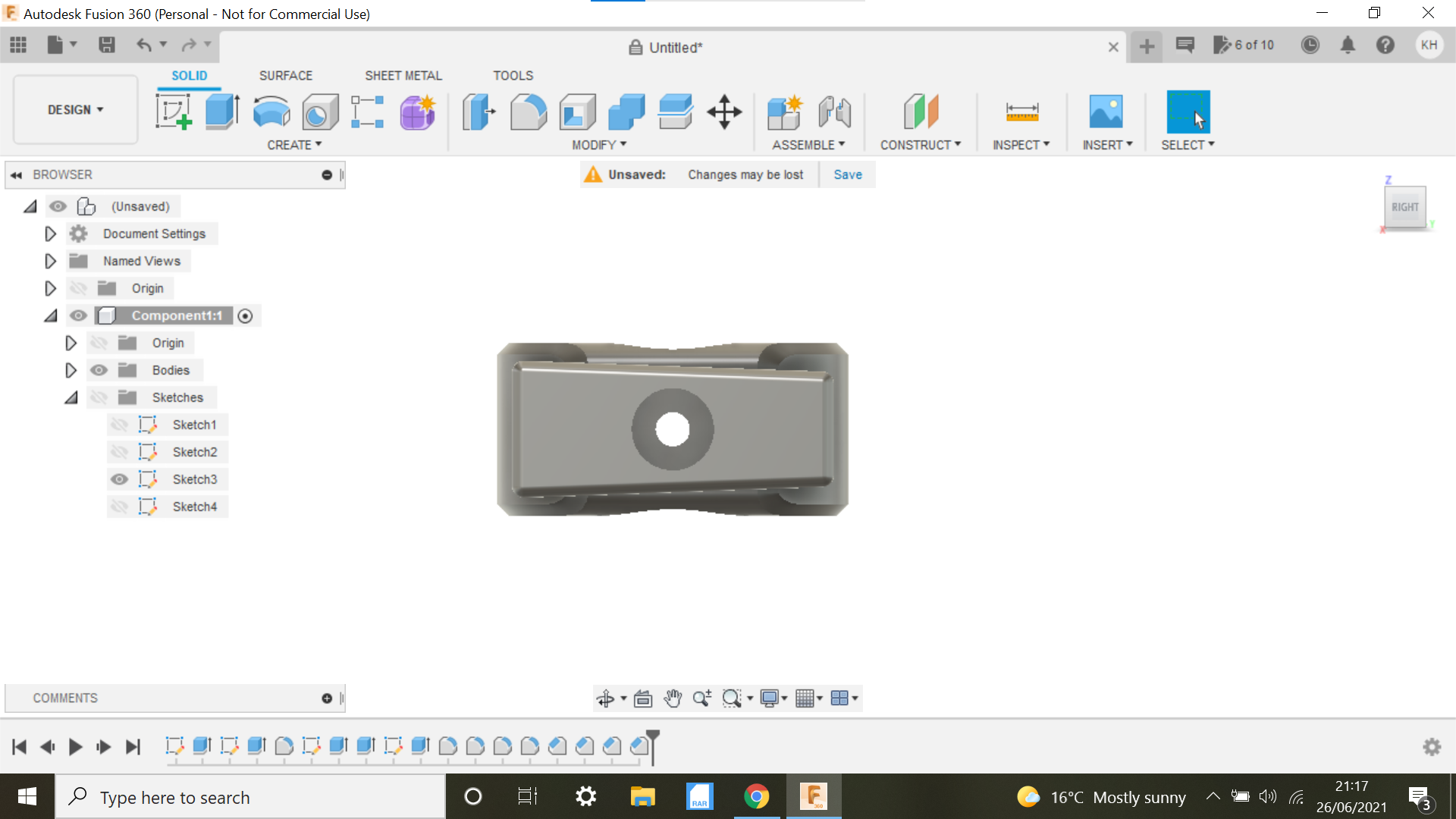
On the bottom of the light is a protrusion which houses the insert for the screw, this needs to be sunk into the bracket, this circle was 7.33mm and extruded to -3mm then a 3mm hole needs to be made for the screw to secure the light to the bracket, the head of the screw needs to to be sunk into the underside of the bracket so as not to interfere with the handle bar so a 1mm extruded recess is created using the mid plane to sketch the 8mm circle then - extrude cut so it just cuts into the bracket by 1mm.
What I usually do with 3D components like this is to print a prototype with no frills, when you have a work then all that is left to do is make it look a bit prettier by adding fillets and chamfers etc.
3D Printing the Bike Light Bracket and Assumptions.
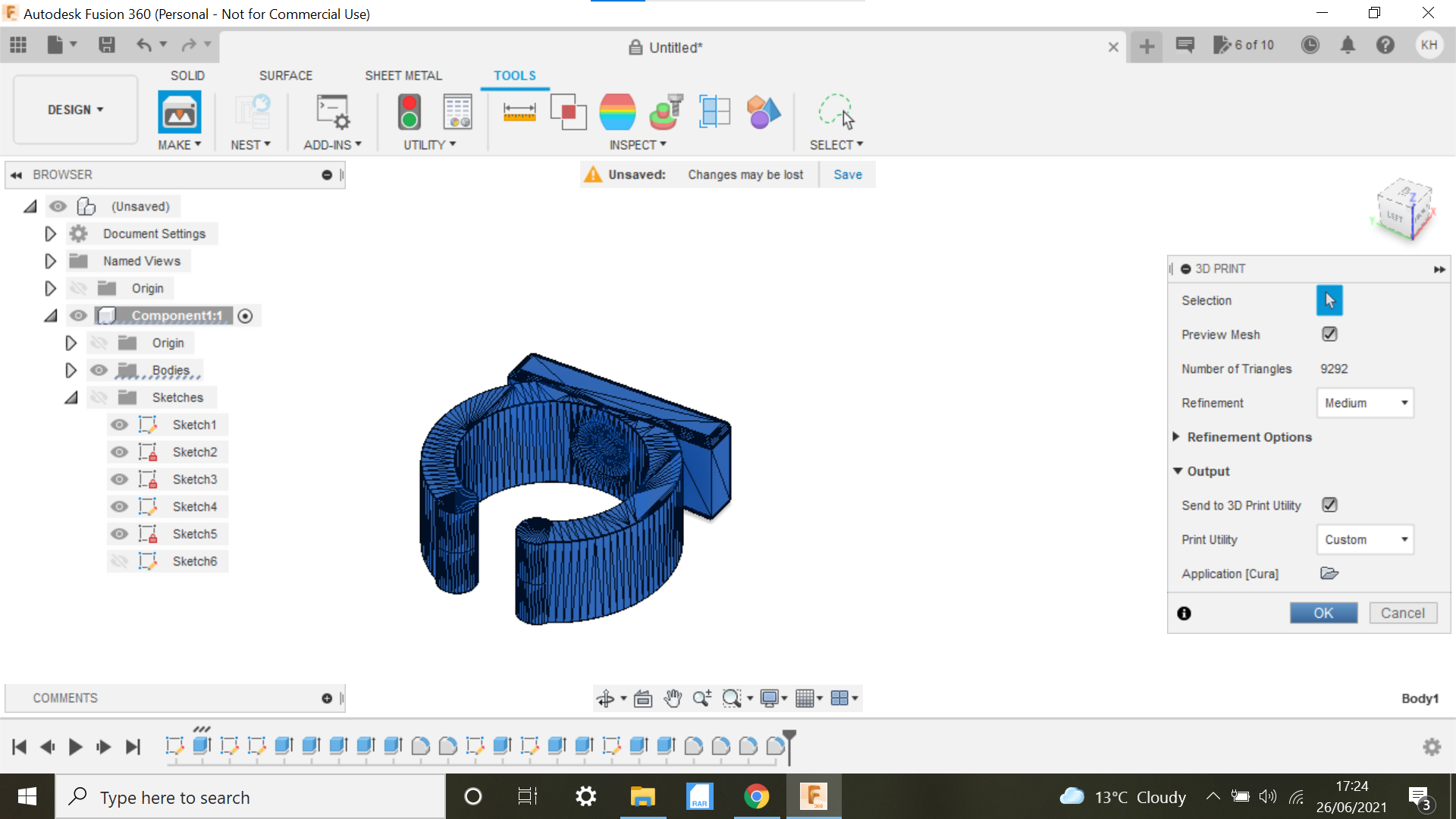
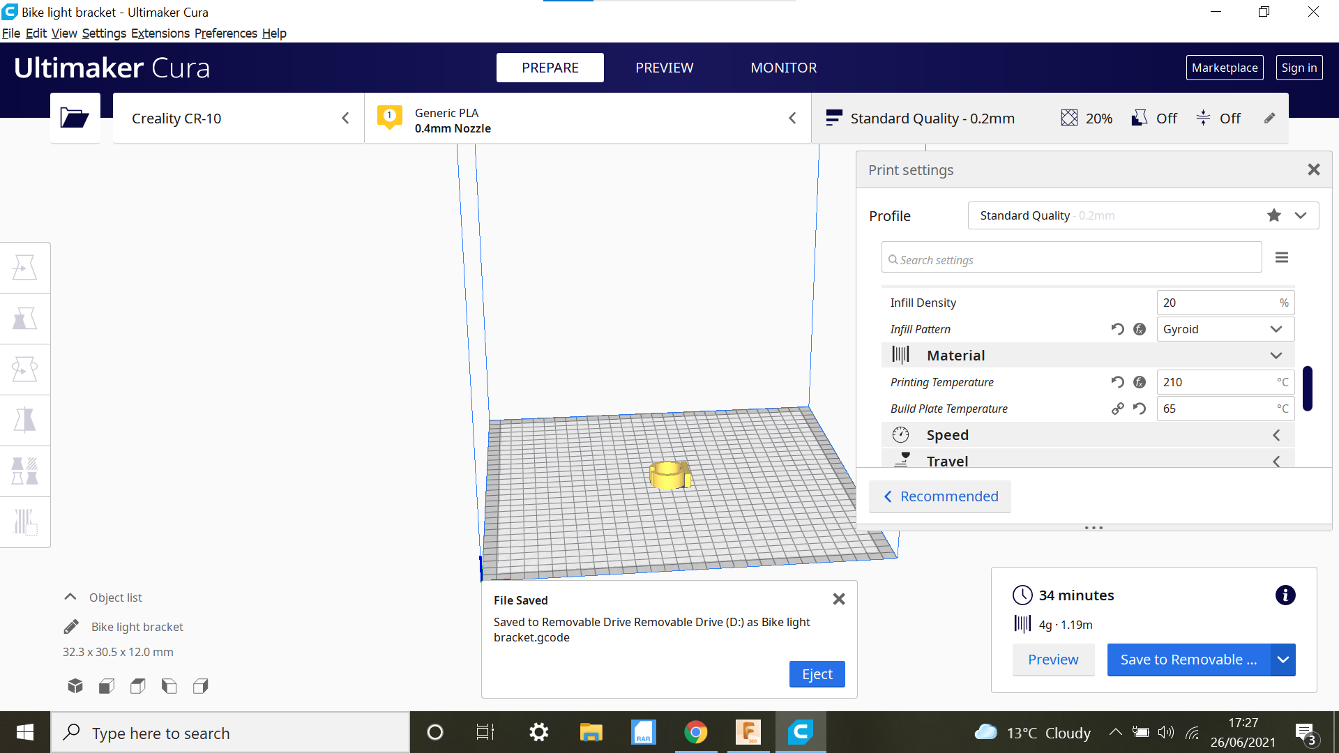
No frills with this 3D print, no supports needed, I am using a Creality CR-10 and the nozzle setting is 210 degrees and the bed 65 Degrees this works for me on the Creality Glass plate print bed.
Another thing I stick to rigidly is to initially always clean the bed with Methylated spirit and always let the Glass print bed completely cool down after the print, it doesn't take that long, there is always an eagerness to get the part off and try it (I am the guilty party here) Sit on your hands! It works, the part just glides off the bed.
Assumptions:
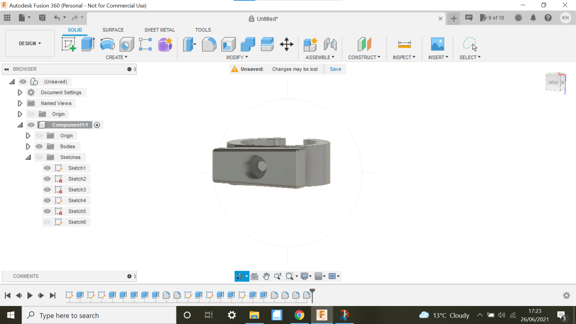
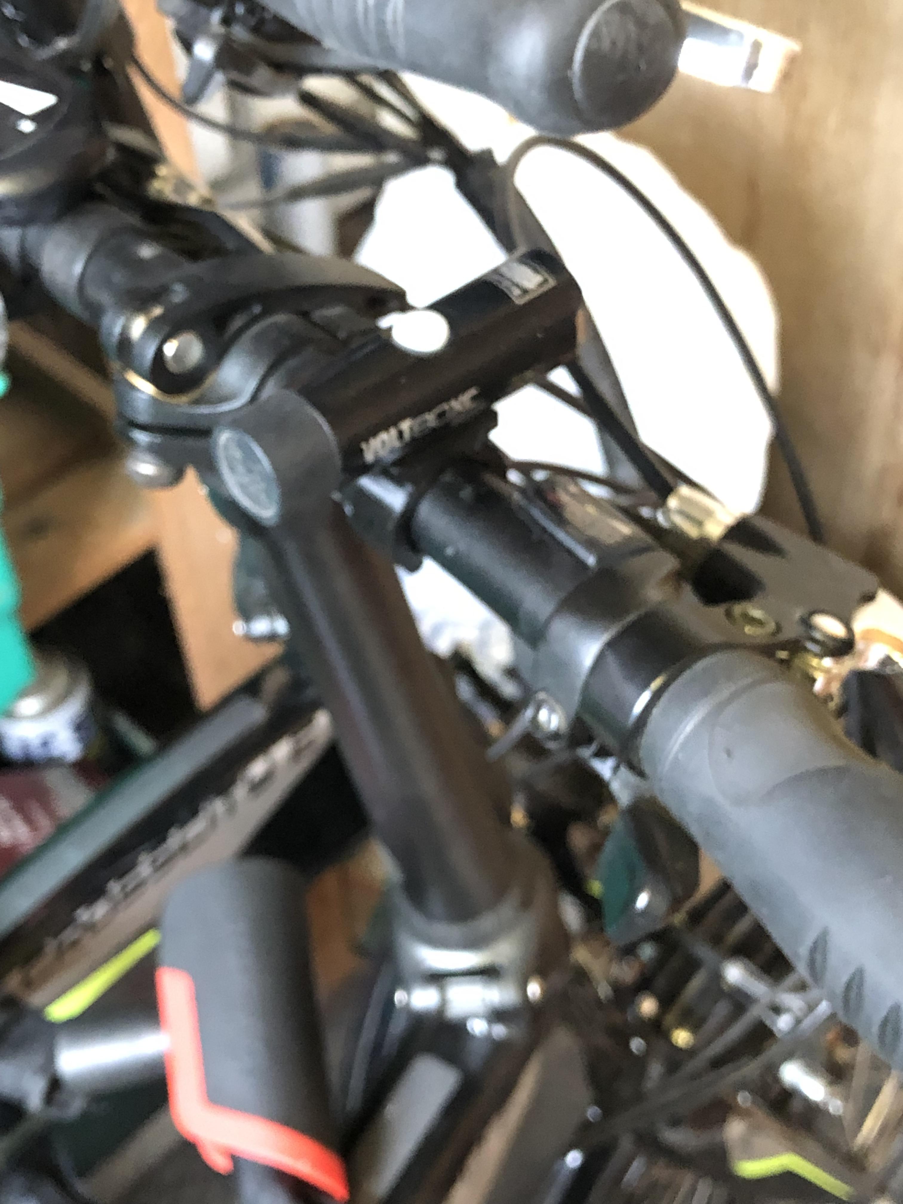
Well the prototype was far too tight to push onto the bar, the gap between the ends of the bracket was too close, and also in Cura the infill was set to Gyroid there was little or no flex, the next attempt was printed using Triangles which in theory should give more flexibility, after trying the 2nd bracket I did another design but did away with the taper where the light would sit, I wanted a print with no support so making it just a plain rectangular shape did the trick and made for a cleaner print.