3D Printed Voltage Regulator Circuit Like PCB Circuit
by osdoyi in Workshop > 3D Printing
4810 Views, 54 Favorites, 0 Comments
3D Printed Voltage Regulator Circuit Like PCB Circuit


3D Printed Voltage Regulator Circuit like PCB,
Everyone knows that preparing a handmade PCB requires lots of knowledge and experience. You need to deal with acids and solders. With the enhancement on filament designs, today we are able to print conductive parts. So why not we 3D print circuits like PCB?
Here is my first 3D printed circuit like PCB. It is a voltage regulator that receives 5V to 12V as an input and gives constant 5V as an output. It is very easy to make. Just like plug and play, plug the circuit components and it will start working.
3D Printing Voltage Regulator's Circuit Board


3D printing Voltage Regulator's circuit board,
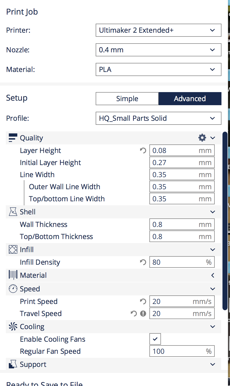
Printing setting of this part actually depends on you. However, I provide my settings in the pictures as well. The main issue is to be strong enough, you don't want it to be broken easily. Attached, you can find .stl file to print regulator circuit board. I used green PLA just to keep PCB color.
Downloads
3D Printing Conductive Lines


3D printing Conductive Lines,
This is the most important step. Printing conductive lines. I buy my conductive PLA from Amazon. It worked very well but e careful about the resistance of the material. You want as low resistance as possible otherwise the circuit won't be an effective one.
Print these lines according to the setting that I provide. It is really tricky and you need to be slow while you are printing. The diameter of conductive PLA is 1.75mm which is not supported by Ultimaker, so I have publish another instructable only for this purpose. How to use 1.75 mm filament with Ultimaker2. Please read that instructable and follow the steps if you are willing to use Ultimaker for this project.
You can download the attached .stl file for line design and start 3D printing conductive lines!
If you want to buy Conductive PLA: https://www.amazon.com/gp/product/B01BDL4BY0/ref=...
Downloads
Assembling Voltage Regulator Circuit


Assembling Voltage Regulator Circuit,
To assemble the voltage regulator, you will need 5 circuit parts.
Here is the list:
1) 7805 5V voltage regulator (x1)
2) 100 micro farad capacitors (x2)
3) Screw-head circuit pins(x2)
With all these parts your circuit will be ready soon. First plug the 7805 into middle of the circuit. When you look at the circuit you will realize +,- signs that indicates power and ground. Middle leg of the 7805 should be inside of the ground hole. Second, plug 100 microfarad capacitors. Third, connect Screw-head circuit pins to the edges of our circuit. For all these components there are different holes on the printed board. See the pictures
Your circuit is ready for a test.
First Trial of the 3D Printed Voltage Regulator Circuit


First trial of the 3D Printed Voltage Regulator Circuit,
I used a power supply to give 10V as an input to my 3D printed circuit. I gave 10V via jumper cables and receive 5.023V at the output, I measured it with the multimeter.
You can see my connection and voltage values from the pictures.
Warning: Just make sure that there is no shortcut on your circuit
Bonus: 3D Printing Simple LED Circuit


Bonus: 3D printing simple LED circuit,
Here is much simple circuit. A basic LED circuit. Please use the conductive line settings for conductive lines and circuit board settings for circuit board. I mark them differently.
After you print both parts attach them to form one circuit. See the last picture
Assemble Simple LED Circuit and Make It Work


Assemble simple LED Circuit and make it work,
To assemble the simple LED circuit, you will need 2 circuit parts.
Here is the list:
1) Screw-head circuit pin
2) LED (3V)
First plug the Screw-head circuit pin to the edge of our circuit. Then connect the LED into other end of our circuit. See the pictures Your circuit is ready for a test.
I used a power supply to give input to my 3D printed circuit. You can see my connections in the pictures. Also I would like to indicate that, LED is a little dimmed because my conductive lines are carrying high resistance.
Warning: Just make sure that there is no shortcut on your circuit
2 Basic Circuits and Things to Pay Attention


2 Basic Circuits and Things to Pay Attention,
I hope you enjoy with these simple 3D printed PCB like circuits. It i very easy to build them and assemble them. However, there are efficiency drawbacks.
Here is the list to pay attention for bigger projects:
1) Be careful about resistance per mm or cm. If its too high your circuit will be inefficient
2) Lines are fragile, be very gentle to them
3) Check any shortcuts, you don't want to harm your components
4) Measure pin diameter correctly and design your conductive lines accordingly. Don't forget to put tolerance. In my case I put 0.3 mm tolerance. For example if the pin diameter were 1 mm, I designed a 1.3mm hole.
Have fun with your new circuit ideas and projects :)