3D Printing and Driving
by dilanmehta1 in Workshop > 3D Printing
6383 Views, 17 Favorites, 0 Comments
3D Printing and Driving


Admit it. You text and drive. According to the CDC, almost 400,000 people were injured and almost 3,000 were killed in car crashes caused by distracted drivers in 2018 alone. To save numerous lives each year, I aspired to design a phone mount that can be created by almost anybody. Although 3D printers, necessary for this project, are uncommon in households, they are widespread in libraries and schools. The power to save lives is at your fingertips. Not only does this device have a positive world impact, it additionally makes using your smart phone while driving more convenient. Other products, such as the suction cup design (although not heavily enforced), are illegal in many states and can cost around $20. To fix these problems, this mount does not obstruct the driver's view of the road, making it allowed almost everywhere and it can be fabricated for less than three dollars in material costs. The final significant factor of this design is compatibility; although rare, some cars have vent slits that run vertically and smart phones constantly vary in size. This design is compatible with vertical and horizontal vent slits and is engineered to work with almost all phone sizes. It is also convenient because of its ball joint, which allows you to angle the cellphone towards you. If you are up for a challenge, follow along with the design process. Otherwise, you can simply download the STL files here: https://drive.google.com/drive/folders/1LHe8Nrx_mQ... and skip through the engineering steps.
Demonstration of the ball joint in action (also on the last step):
Supplies
To do this project yourself, you will need a 3D printer, a free Tinkercad account, slicing software, support removal tools or pliers, a hot glue gun, 2 small springs (can be obtained by taking apart a pen), sandpaper, and PETG or PLA 3D printer filament. You might also need a hammer or a pestle to drive the ball joint into its socket. For the filament, PETG is the best choice because it will make the device stronger and be more resistant to heat from the vent, but PLA, which is more accessible and easy to use, can also work.
Designing the First Vent Clip


For the entire design process, follow the pictures in order while reading their corresponding steps. First, create a box that is 39.25 mm by 20 mm by 3 mm. Then, duplicate by selecting it and clicking command or control D it and change one of its horizontal dimensions to 2 mm and change its height to 4.5 mm. Make sure to not disturb the position of the piece, as shown in the second picture. Next, duplicate the first shape again and change the horizontal dimensions to 42.75 mm by 3.5 mm, making sure its position matches the third picture. Do the same for the other side. Then create a cylinder as a hole and change its diameter to 7 mm. Do not change the other dimension, which defaults to 20 mm. Once you have done that, you can now group the four solid shapes from earlier by selecting all of them and clicking command or control and G. After that, select the two resulting shapes and align the cylinder to the middle of the back using the align tool near the top right corner. Then use the arrow keys or type in the box to move the cylinder 3 mm away from the end, as shown in the sixth picture. Make sure not to move it along any other dimensions. Then, duplicate the newly located cylinder and move it 27 mm in the same direction. Double check that all of the three shapes stayed center aligned and then group them to finish the first piece that will grasp onto the vents of your car. The holes you added were spaces for the spring to go so that it pushes outward and holds the phone in place using the vent.
Designing the Second Vent Clip - Part 1


This piece serves as the second clip for the vent and also holds in place the ball joint, which allows the phone to rotate. In this step, you will create the portion of it that sticks into the vent. Start by creating a box that is 2 mm by 25 mm by 4 mm. Then, duplicate it and use the bottom slider to change the height of the new shape to 2.5 mm so that it goes up in elevation, as shown in the second picture. Then, extend it out to 57 mm, not changing the other dimension of the shape. After that, group the two solids in the design. Just like last step, create a cylinder as a hole that is 7 mm in diameter without changing its height, but elevate it by 2 mm. Align it to the center and the back of the other shape and then move it 3 mm away from the back. Duplicate the cylinder and move it 27 mm in the same direction. These slots will line up with the other pieces that the springs can be glued into them. Double check the alignment and then group the shapes you created in this step.
Designing the Second Vent Clip - Part 2


In this step, you will finish the almost all of the piece from the previous one by adding the socket that holds the ball joint. First, create a box that is 25 mm by 14 mm by 24 mm and elevate it 2 mm off of the ground. Then, align it to the back center of the shape from the last step, as shown in the fourth image. Next, duplicate the shape and change the dimension of the new one that was 25 mm to 12 mm. Along one dimension, center align the three shapes shown in the seventh picture and then group them. After that, create a sphere with a diameter of 20.5 mm and make it hole. Align this sphere to the back center of the other shape. Use the alignment parameters in the eight screenshot. Then move the sphere 7.25 mm in the direction away from the other shape. Finally, group the shapes.
Designing the Second Vent Clip - Part 3


This step is optional; doing it will make this piece less sharp and therefore easier to handle. Go to the shapes menu and find shape generators and then click all. Scroll to page 12 (usually) and create the shape called "metafillet" as a hole. Change its horizontal dimensions to 5 mm by 5 mm and extend its height extremely. Next, rotate this shape by 90 degrees. Then, align it to the top right corner of the piece from the last step. Once you have done that, duplicate the metafillet and use the flip tool to reflect it the other way. After that, align it with the top left corner and group the three shapes. You are done designing this piece!
Designing the Ball Joint


To start designing the ball join, create a box that is 20 mm by 20 mm horizontally and 2.5 mm vertically. Then, create a cylinder that is 8 mm by 8 mm by 18 mm and center align the two shapes horizontally. After that create a sphere with a diameter of 20 mm and elevate it 14 mm off of the workplane. Center align the three shapes horizontally and group them to finish the ball join. The bottom part of it will attach to another piece that holds the phone and the top part, the sphere, will be inserted into the socket from the previous few steps.
Designing the Phone Holder Arms


In this step, you will design the part that holds the sides of the phone. To start, create a cylinder and distort it to 10 mm by 6 mm horizontally make it 28.25 mm in height. Then, duplicate it and change its height to 3 mm using the bottom slider so that it moves up in elevation. Next, create box that is 38 mm by 4 mm by 2.5 mm. Align in to the middle of the back of the other two shapes horizontally, as shown in the screenshot. After that, duplicate it and change its dimensions to 1.25 mm by 5 mm so that it is in the far corner of the box. Make it hole and then move move 5 mm towards the other shape. Do the same for the other side to finish the arm. These slots will be important to lock the adjusting phone holder in place. Group these shapes and then duplicate the resulting body to create the two identical arms.
Designing the Phone Holder Backbone - Part 1


The part you will design in the next few steps holds the arms and the end of the ball joint to allow the phone holder to rotate and support the phone. Create a box that is 50 mm by 13 mm by 6 mm. Create another one as a hole and make it 90 mm by 8 mm by 6 mm. Center align the two shapes on all three dimensions. Then create another solid box that is 25 mm by 71 mm by 6 mm. Select the two solid shapes and align the new one to the center of the back. Group the three shapes you have created. Next, create a metafillet (from shape generators page 12) and scale it to 12.5 mm by 58 mm by 6 mm. Align it with the bottom right of the other body horizontally. Repeat that for the other side of the backbone piece and group the shapes.
Designing the Phone Holder Backbone - Part 2


First, create a box as a hole that is 8 mm by 40 mm by 3 mm. Align it with the back of the middle of the shape from the previous step. Then, move it 2.25 mm into it without changing its position along any other dimension. Group the shapes. Next, create another box-shaped hole. Change its height to 3 mm and its horizontal side lengths to 21 mm. After that, center align this hole with the other solid shape and group them.
Designing the Phone Holder Backbone - Part 3


Start by creating a box that is 3 mm by 5 mm by 30 mm. Temporarily ungroup the shape from last step completely. Align this shape to the bottom corner of the rectangular backbone piece. Next, duplicate it and align the new one to the other bottom corner. Then, duplicate each one and change the height from the bottom to 3 mm so that it goes up in elevation. Finally, extend the length of 3 mm to 8 mm for each one in the direction of the rest of the part.
Designing the Phone Holder Backbone - Part 4


Create another metafillet and rotate it 90 degrees as shown in the first picture. Resize it to 5 mm by 3 mm by 5 mm. Then, align it to the bottom corner of the other shapes, as shown in the picture. Next, elevate it by 6 mm and move inwards by 5 mm. Repeat the same for the other side so that the design looks like the fifth picture. After that, create another metafillet and rotate it 90 degrees so that it resembles the sixth picture. Set the size to 5 mm on all three dimensions. Elevate it off of the workplane by 6 mm. Next, align it to the corner horizontally of the main shape that forms the backbone piece. After that, move it 3 mm towards the other end. Repeat the same process for the other side.
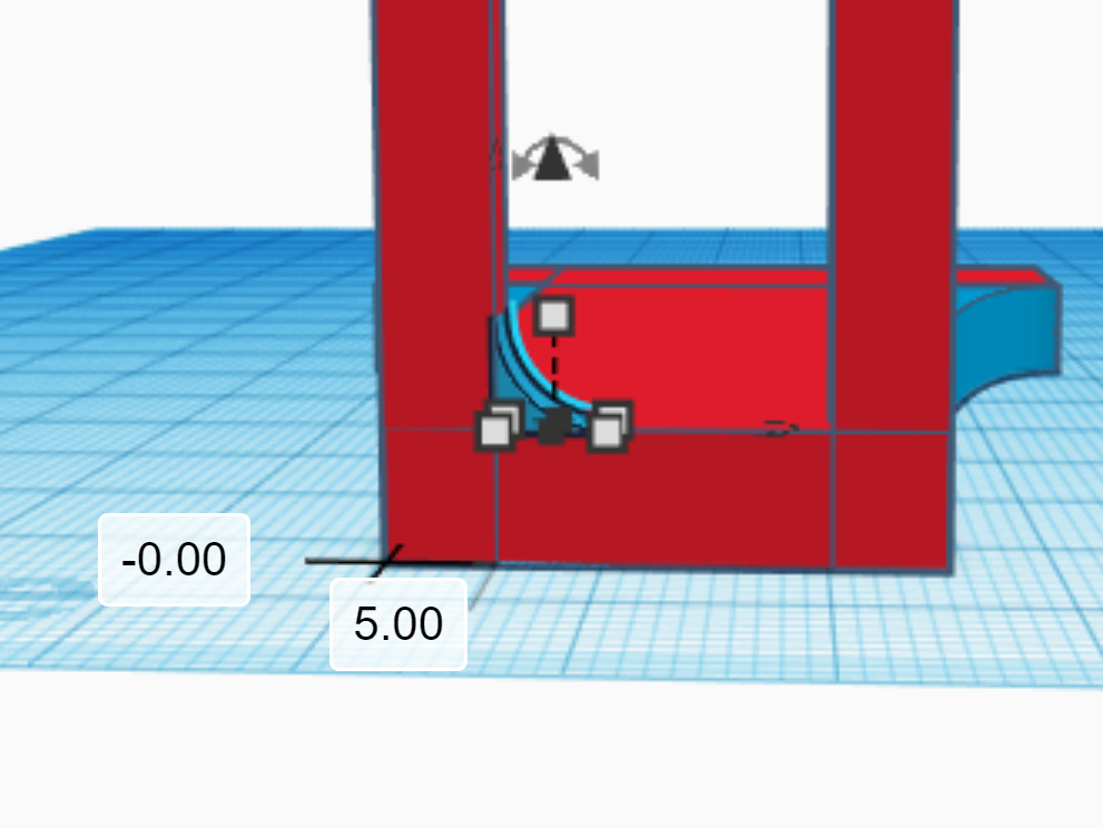
Designing the Phone Holder Backbone - Part 5


![87].PNG](/proxy/?url=https://content.instructables.com/F5X/YR6C/KIN511J4/F5XYR6CKIN511J4.png&filename=87].PNG)

In this step, you will finish the phone holder backbone. Start by creating a 3 mm by 3 mm metafillet (do not change the height) and elevate it by 27 mm. Then, align it to the corner of the shape shown in the third image. Next, duplicate it and then flip the new shape. After that align it to the other side, as shown in the fourth image. Do the same for the other protruding shape and group all of the shapes you have created in the last five steps.
Designing the Holder Clips


The piece you will design in this step will secure the arms in place on the backbone piece with the help of hot glue. Create a box that is 2.75 mm by 4.5 mm by 4.25 mm. Then, make another one that is 7.5 mm by 4.5 mm by 1.5 mm. Align this box to the back center of the other one. Then, duplicate the first box and align the new shape to the other end of the second box. Group these shapes and duplicate the resulting one to indicate that you will need two of these clips, one for each arm. Great job if you have made it this far; you are done with the design.
The design above shows the different parts you have made and on the side is an assembled version to show their functions.
Slicing the STL Files Into GCODE


In order to actually print the designs, you will need to convert them into a file format that a 3D printer can understand. Slicing software accomplish this task by converting .stl files to .gcode files, which give instructions through settings such as speed, infill, temperatures, and layer height to the 3D printer. If you designed the parts in Tinkercad, select one shape and click export. Then, click "the selected shape" and ".STL". Open the file you exported in your slicing software. Export or download each shape individually. If you need to download a slicing software, I would recommend Cura because it is free. It is also both user-friendly and sophisticated, so you can change the settings in detail according to your experience with 3D printing. 3D print each of these pieces individually using the settings in the image above (they depend on what filament you are using). Make sure to arrange the parts in your slicer so that they print with a larger side as the base. Feel free to adjust any of the settings to suit your particular machine. Finally, give the files to the 3D printer and let it fabricate each part. Ensure that you load the right filament according to the settings you established.
Post-Processing the Printed Parts

To refine your prints, use pliers to remove support material and use sandpaper to smoothen surfaces if needed. Start with a rough sheet and then use a smoother one.
Assembling the Printed Pieces - Part 1


After printing and post-processing the parts, you will need to assemble them together. Start by wedging the ball joint into its respective place in the second vent clip. This will take a lot of force, but be careful because you could break the printed parts, especially if they are made of PLA. You may even want to gently tap it with a hammer or a pestle. The ball will fit in tightly, which is important so that the friction is enough to keep up the phone weight while allowing it to rotate. After you have done that, take the two small springs (can be obtained from a pen) and glue them into each circular hole in the second vent clip. Finally, glue the other end of each one into their respective places in the first vent clip.
Assembling the Printed Pieces - Part 2


Put those parts aside for now. Take the arms and insert them into the slot at the top of the phone holder backbone, one on each side. Position them so that they are the right distance apart to grip your phone relatively tightly. Ensure that if you put your phone in between the arms, the charging port is not blocked at the bottom. Next, push the holder clips onto the narrower part of arms from the back and hot glue the pieces together. After that, combine the parts from last step with those from this step by gluing the end of the ball joint to the slot at the back of the phone holder backbone. Use pliers to straighten it out if needed. You are done with assembly!
Installing the Mount


To install the device into your car, firmly squeeze the springs together and slide the two vent clips between two flaps of the vent (horizontal or vertical). Then, let go and it should latch on, holding your phone up. Insert you phone and enjoy! Make sure that the ball joint turns, but holds firmly even with your cell phone in it. Here is a demonstration of how the ball joint should look:
Thank you for your interest in this Instructable and I hope you vote for my project to win the Plastics Contest.